EP1380249B1 - Lave-vaisselle - Google Patents
Lave-vaisselle Download PDFInfo
- Publication number
- EP1380249B1 EP1380249B1 EP02258754A EP02258754A EP1380249B1 EP 1380249 B1 EP1380249 B1 EP 1380249B1 EP 02258754 A EP02258754 A EP 02258754A EP 02258754 A EP02258754 A EP 02258754A EP 1380249 B1 EP1380249 B1 EP 1380249B1
- Authority
- EP
- European Patent Office
- Prior art keywords
- filter
- dishwasher according
- wash water
- duct
- housing
- Prior art date
- Legal status (The legal status is an assumption and is not a legal conclusion. Google has not performed a legal analysis and makes no representation as to the accuracy of the status listed.)
- Expired - Lifetime
Links
Images



Classifications
-
- A—HUMAN NECESSITIES
- A47—FURNITURE; DOMESTIC ARTICLES OR APPLIANCES; COFFEE MILLS; SPICE MILLS; SUCTION CLEANERS IN GENERAL
- A47L—DOMESTIC WASHING OR CLEANING; SUCTION CLEANERS IN GENERAL
- A47L15/00—Washing or rinsing machines for crockery or tableware
-
- A—HUMAN NECESSITIES
- A47—FURNITURE; DOMESTIC ARTICLES OR APPLIANCES; COFFEE MILLS; SPICE MILLS; SUCTION CLEANERS IN GENERAL
- A47L—DOMESTIC WASHING OR CLEANING; SUCTION CLEANERS IN GENERAL
- A47L15/00—Washing or rinsing machines for crockery or tableware
- A47L15/42—Details
- A47L15/4202—Water filter means or strainers
- A47L15/4206—Tubular filters
Definitions
- the present invention relates to a dishwasher including a housing, a chamber to receive items to be washed and a removable filter for filtering wash water, the filter being received in a duct through which wash water in the chamber circulates, wherein the dishwasher is configured so that the filter is removable from the housing without gaining access to the chamber.
- a dishwasher is disclosed in JP 2000-014620A .
- Dishwashers having similar removable filters are also known from US 1638549A and DE 1192614B .
- a conventional dishwasher is illustrated in Figure 1 and includes a cabinet 1 and a door 3 hinged at its lower edge to the front of the cabinet to enable it to be opened and closed so that access to a washing tub 2 may be obtained.
- Baskets 2a are slideably installed at upper and lower positions within the washing tub 2 to receive dishes to be washed.
- An injection nozzle 2c is disposed beneath each of the baskets 2a to spray wash water onto the dishes held in the baskets 2a.
- the injection nozzle 2c is connected to a water supply pipe 2b.
- a water container 4 is mounted at the bottom of the washing tub 2 to collect sprayed wash water circulated through the nozzle 2c by a pump 6.
- a drain pump 5 is also provided below the water container 4 and is connected to the water container via a drain pipe 5a.
- a circulation pipe 6a also connects the water container 4 to the circulation pump 6 and communicates with the water supply pipe 2b which is connected to the injection nozzle 2c.
- wash water When the dishwasher is in operation, the wash water circulates therein.
- the wash water sprayed from the injection nozzle 2c passes through the water container 4, the circulation pipe 6a and the water supply pipe 2b, and returns to the injection nozzle 2c.
- wash water is discharged by the drain pump 5.
- a filtering unit is provided in the water container 4 so as to remove the impurities and filter the wash water.
- the filtering unit comprises a circulation filter 8, and an impurity-collecting filter 9.
- the circulation filter 8 is installed on a central portion of the bottom of the washing tub 2 over the water container 4 and the impurity-collecting filter 9 is received in a hole 8a in the water container 4.
- the hole 8a corresponds to a central portion of the circulation filter 8.
- the circulation filter 8 is dished so that it inclines downwardly toward the hole 8a so that impurities are guided into the impurity-collecting filter 9. Perforations are formed throughout the circulation filter 8, so that impurities remain trapped in the circulation filter 8while the wash water passes through the perforations. The impurities remaining in the circulation filter 8 are guided to the hole 8a by the circulation filter 8 and are collected in the impurity-collecting filter 9.
- the impurity-collecting filter 9 has a cylindrical shape, and has filtering perforations in its sidewalls so that impurities remain in the impurity-collecting filter 9 while the wash water passes through the filter perforations, thus the filtered impurities are collected in the impurity-collecting filter 9.
- a problem with a conventional dishwasher is that some impurities accumulate on the upper surface of the circulation filter 8 without moving into the impurity-collecting filter 9 along the upper surface of the circulation filter 8.
- both the circulation filter 8 and the impurity-collecting filter 9 are installed at the bottom of the washing tub 2 such that the circulation filter 8 and the impurity-collecting filter 9 are exposed to an interior of the washing tub 2.
- the impurities which have accumulated on the upper surface of the circulation filter 8 or have collected in the impurity-collecting filter 9 are visible, thus creating an unpleasant experience for the user.
- the impurity-collecting filter 9 must be removed and cleaned periodically. However, this is difficult. Furthermore, when the user removes the impurity-collecting filter 9 from the cabinet 1, dirty water held in the impurities, such as food residues collected in the impurity-collecting filter 9 may fall from collecting filter 9 and contaminate the interior of the washing tub 2.
- a dishwasher according to the present invention is characterised in that a perforated guide member through which wash water entering the duct from the chamber flows, impurities in the wash water being caught by the guide member and directed into the filter.
- the housing includes an opening and a cover through which access to the duct may be obtained when the cover is detached from the housing.
- the guide member is funnel shaped and terminates within the filter.
- the filter comprises a plurality of cylindrical members nested together, each cylindrical member being formed from a mesh having different size perforations.
- the dishwasher comprises a cabinet 10.
- a door 30 is hinged to a lower portion on the front of the cabinet 10 and a space within the cabinet 10 defines a washing tub 2 to receive dishes to be washed.
- the door 30 enables access to the washing tub 20 to be obtained.
- Two baskets 21,22 for receiving dishes are slidably received in the washing tub 20.
- Upper and lower injection nozzles 23,24 are mounted beneath each of the upper and lower baskets 21,22 respectively, and spray wash water onto dishes placed in the upper and lower baskets 23,24.
- the upper injection nozzle 23 is connected to a first water supply pipe 25 at the top of the washing tub 20, and the lower injection nozzle 24 is connected to a second water supply pipe 28 at the bottom of the washing tub 20.
- a water container 40 is installed in the cabinet 10 under the washing tub 20 to collect wash water.
- the washing tub 20 is provided on a bottom surface 26 thereof with an inlet 27 through which water from the washing tub 20 flows into the water container 40.
- the bottom surface 26 of the washing tub 20 is inclined towards the inlet hole 27.
- An upper end of the water container 40 is mounted to the bottom surface 26 of the washing tub 20 around the inlet hole 27, so that the water container 40 is installed under the washing tub 20.
- a circulation pump 50 is installed in a vicinity of the water container 40 to circulate the wash water in the dishwasher, and a drain pump 60 is installed at a lower position of the water container 40 to discharge the wash water from the water container 40.
- a circulating pipe 51 connects the circulation pump 50 to the water supply pipes 25,28 and a drain pipe 61 connects the drain pump 60 to the water container 40.
- the circulation pipe 51 supplies wash water to the first and the upper and lower injection nozzles 23,24 respectively via the water supply pipes 25,28.
- the wash water When wash water is sprayed from the upper and lower injection nozzles 23,24 respectively, the wash water sequentially passes through the water container 40 and via the circulation pump 51 through the water circulation pipe 51 and then flows into the first and second water supply pipes 25,28 and is again supplied to the upper and lower injection nozzles 23,24 respectively. After a predetermined period of time has elapsed, the wash water is discharged from the dishwasher through the drain pipe 61 by operation of the drain pump 60.
- a filtering unit is provided in the water container 40 to remove the impurities from wash water while it circulates in the dishwasher.
- the filtering unit comprises an impurity-collecting filter 70 and a guide member 80 which connects the washing tub 20 to the impurity-collecting filter 70 such that wash water from the washing tub 20 flows into the water container 40 through the impurity-collecting filter 70.
- the impurity-collecting filter 70 is removably mounted in the water container 40 through an aperture 11 in the front surface of the cabinet 10 so as to allow the impurity-collecting filter 70 to be removed for cleaning.
- the opening 11 allows the impurity-collecting filter 70 to be directly mounted in the water container 40 through the front surface of the cabinet 10 below the door 30.
- the water container 40 includes an extended portion 41 in which the impurity-collecting filter 70 is received.
- the extension part 41 is formed so as to terminate at the opening 11.
- Wash water from the washing tub 20 passes into the water container 40 via the inlet hole 27 whilst impurities are guided by the guide member 80 into the impurity-collecting filter 70.
- a plurality of perforations 81 are formed in the guide member 80, so that the wash water passes through the perforations 81 while impurities are caught in the guide member 80.
- the guide member 80 is provided on the bottom surface 26 of the washing tub 20 around the inlet hole 27, and is downwardly tapered or funnel shaped.
- a bent part 82 is provided at a lower end of the guide member 80 and extends in a common direction as a direction of extension of the extension portion 41.
- An insertion part 82 is provided at an end of the bent part 82 so as to extend into a filtering unit 72 of the impurity-collecting filter 70 to guide impurities into the impurity-collecting filter 70.
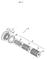
- the impurity-collecting filter 70 comprises a stopper 71 and the filtering unit 72.
- the stopper 71 closes the opening 11 which is in the front of the cabinet 10 and closes the extension part 41 of the water container 40, at the same time.
- the filtering unit 72 is installed in the extension part 41 within an area defined by the extension part 41 so as to filter impurities guided by the guide member 80.
- the filtering unit 72 is removably mounted to the stopper 71 at one end and to the guide member 80 at the other.
- the stopper 71 comprises an outer part 73, an intermediate part 74 and an inner part 75.
- the outer part 73 closes the opening 11 and the inner part 75 engages with the extension part 41 around the opening 11 with a screw-type fastening.
- the intermediate part 74 is provided between the outer and inner parts 73,75.
- An external thread is formed on an outer surface of the inner part 75, and an internal thread is formed on an inner surface of the extension part 41 which cooperates with the externally threaded inner part 75, thereby engaging the stopper 71 with the extension part 41 around the opening 11.
- a knob 73a is provided on the outer part 73 to allow a user to rotate the stopper 71.
- the inner part 75 engages with or disengages from the extension part 41 around the opening 11 according to the rotation of the knob 73a, the impurity-collecting filter 71 is attached or removed from the extension part 41.
- a ring-shaped sealing member 90 is provided on an outer surface of an intermediate part 74, and seals a gap between an inner surface of the outer part 73 of the stopper 71 and an end of the extension part 41 so as to prevent the egress of wash water from the water container 40 via a gap between the extension part 41 and the stopper 71.
- the filtering unit 72 is detachable from the stopper 71 and comprises three filtering parts 76-78, each having a cylindrical shape open at one end and perforated to allow the wash water to circulate therethrough.
- the filtering unit 72 has a multi-filter structure which is capable of selectively and sequentially collecting the impurities according to a mesh of the three filtering parts 76-78.
- the filtering unit 72 comprises nets having different mesh sizes.
- the inner filtering part 76 is provided at an inner position of the filtering unit 72 to filter large impurities.
- a first outer filtering part 77 concentrically surrounds the inner filtering part 76 filtering the impurities which are smaller than the impurities filtered by the inner filtering part 76.
- a second outer filtering part 78 is provided outside of the first outer filtering part 77, and finally filters fine impurities which pass the first outer filtering part 77.
- the three filtering parts 76,77,78 of the filtering unit 72 are detachable from the stopper 71 and are easily separated from each other, thus allowing a user to easily clean the filtering unit 72.
- the stopper 71 has, at an inner position thereof, ring-shaped triple locking grooves 75a. Ends of the filtering parts 76,77,78 can be inserted into or removed from an associated ring-shaped triple locking groove 75a.
- the insertion part 83 of the guide member 80 is inserted into the filtering unit 72 to a predetermined length.
- the three filtering parts 76,77,78 of the filtering unit 72 are provided with insertion holes 79.
- the insertion holes 79 have a common cross-section as that of the insertion part 83 and are sequentially arranged, as shown in Figure 3 , when the three filtering parts 76,77,78 are assembled to produce the filtering unit 72.
- the outer surface of the insertion part 83 may be in close contact with the insertion holes 79 so as to prevent the impurities caught by the filtering unit 72 from unexpectedly leaking through a gap between the filtering unit 72 and the guide member 80.
- the filtering unit 72 may have a simple cylindrical shape or the filter unit 72 may be slightly bent so as to prevent the impurities caught by the filtering unit 72 from undesirably re-entering the guide member 80 during the circulation of the wash water.
- the dishwasher allows the wash water to circulate from the water container 40 to the washing tub 20, via the guide member 80 and the impurity-collecting filter 70, by operation of the circulation pump 50. Further, the dishwasher allows the impurities existing in the wash water to be easily filtered by the impurity-collecting filter 70.
- a user When the impurity-collecting filter 70 needs cleaning, a user first confirms that the operation of draining the wash water is finished. Next, the user unscrews the handle 73a of the stopper 71 to disengage the inner part 75 of the stopper 71 from the extension part 41. After that, as shown in Figure 5 , the stopper 71 with the impurity-collecting filter 71 is removed from the cabinet 10. Thereafter, the second outer filtering part 78, the first outer filtering part 77 and the inner filtering part 76 are sequentially removed from the locking grooves 75a which are formed on the inner part 75 of the stopper 71 for cleaning.
- the ends of the filtering parts 76,77,78 are reinserted into the locking grooves 75a formed on the inner part 75 of the stopper 71.
- the stopper 71 with the filtering unit 72 is reattached to the cabinet 10 such that the insertion part 73 of the guide member 80 is inserted into the filtering unit 72 of the impurity-collecting filter 70 by screwing the handle 73a of the stopper 71 in a reverse direction so that the extension part 41 engages with the inner part of the stopper 71.
- the impurity-collecting filter 70 is removably mounted in the cabinet 10 through the front of the cabinet 10 below the door 30, so the impurity-collecting filter 70 is removed from the cabinet 10 without opening the door 30 without removing either of the upper or lower baskets 21 or 22, thus making cleaning easier.
- the impurity-collecting filter 70 is removed from the dishwasher, the dirty water from the impurities collected in the impurity-collecting filter 70 does not exit the impurity-collecting filter 70, thus keeping the bottom surface 26 of the washing tub 20 cleaner.
- the impurity-collecting filter 70 may be changed to another appropriate position and the extension part 41 and opening 11 may be provided on a side surface or a rear surface of the cabinet 10.
Landscapes
- Washing And Drying Of Tableware (AREA)
- Filters For Electric Vacuum Cleaners (AREA)
Claims (16)
- Lave vaisselle qui comprend un habillage (10), une chambre (20) pour recevoir des articles à laver, et un filtre amovible (70) pour filtrer l'eau de lavage, le filtre (70) étant reçu dans un conduit (40) à travers lequel circule l'eau de lavage dans la chambre (20), le lave vaisselle étant configuré de sorte que le filtre (70) puisse être extrait de l'habillage (10) sans aucun accès à la chambre (20), et caractérisé par un élément de guidage perforé (80) à travers lequel s'écoule l'eau de lavage qui entre dans le conduit (40) en provenance de la chambre (20), les impuretés contenues dans l'eau de lavage étant arrêtées par l'élément de guidage (80) et dirigées dans le filtre (70).
- Lave vaisselle selon la revendication 1, dans lequel l'habillage (10) comprend un orifice (11) et un couvercle (71) rendant possible l'accès au conduit (40) lorsque le couvercle (71) est détaché de l'habillage (10).
- Lave vaisselle selon la revendication 2, dans lequel l'élément de guidage (80) est en forme d'entonnoir et se termine à l'intérieur du filtre (70).
- Lave vaisselle selon la revendication 2 ou la revendication 3, dans lequel le filtre (70) comprend une pluralité d'éléments cylindriques (76,77,78) emboîtés, chaque élément cylindrique (76,77,78) étant formé en treillis à ouvertures de mailles différentes.
- Lave vaisselle selon l'une quelconque des revendications 2 à 4, dans lequel le filtre (70) est monté sur le couvercle de façon amovible.
- Lave vaisselle selon l'une quelconque des revendications 2 à 5, dans lequel le couvercle (71) a une partie filetée (75) qui coopère avec une partie filetée correspondante sur l'habillage (10).
- Lave vaisselle selon l'une quelconque des revendications 2 à 6, dans lequel l'orifice (11) est formé sur une surface antérieure de l'habillage (10) et une partie en prolongement (41) du conduit (40) s'étend jusqu'à l'orifice (11) de sorte à recevoir le filtre (70).
- Lave vaisselle selon les revendications 5 à 7, dans lequel le couvercle (71) est monté à une première extrémité du filtre, fermant ladite première extrémité et une partie en prolongement (82) de l'élément de guidage disposée à une seconde extrémité de celui-ci.
- Lave vaisselle selon l'une quelconque des revendications 2 à 8, qui comprend de plus un élément d'étanchéité prévu entre le couvercle et la partie prolongée (41) de sorte à empêcher l'eau de lavage de fuir hors de la partie prolongée (41).
- Lave vaisselle selon l'une quelconque des revendications précédentes, qui comprend de plus une pompe de circulation (50) et une pompe de vidange (60) connectées en des positions prédéterminées du conduit (40) par des tuyaux respectifs, ladite pompe de circulation (50) faisant circuler l'eau de lavage à partir du conduit (40) jusque dans la chambre (20), et ladite pompe de vidange (60) déchargeant l'eau de lavage à partir du conduit (40) vers l'extérieur.
- Lave vaisselle selon l'une quelconque des revendications précédentes, dans lequel le filtre (70) est recourbé de sorte à empêcher les impuretés de retourner dans l'élément de guidage (80).
- Lave vaisselle selon l'une quelconque des revendications 4 à 11, dans lequel le couvercle (31) comprend, sur un de ses côtés, plusieurs rainures de retenue (75a) qui correspondent à la pluralité d'éléments cylindriques (76,77,78) du filtre (70), chaque élément cylindrique (76,77,78) pouvant être introduit dans la rainure de retenue correspondante (75a) ou extrait de celle-ci.
- Lave vaisselle selon l'une quelconque des revendications précédentes, dans lequel la chambre (20) comprend une surface inférieure (26) inclinée vers le bas, et un orifice d'admission (27) prévu sur la surface inférieure (26) qui permet à l'eau de lavage provenant de la chambre (20) de s'écouler dans le conduit (40).
- Lave vaisselle selon la revendication 13, dans lequel l'élément de guidage (80) est placé dans le conduit (40) de sorte que son extrémité supérieure communique avec l'orifice d'admission (27).
- Lave vaisselle selon l'une quelconque des revendications précédentes, qui comprend de plus une porte (30), le filtre (70) étant placé dans la cuve à eau à travers une surface extérieure de l'habillage (10) au-dessous de la porte (30).
- Lave vaisselle selon l'une quelconque des revendications 1 à 6, dans lequel la partie en prolongement (41) qui reçoit le filtre (70) est prévue sur une surface latérale ou sur une surface postérieure de l'habillage (10), et l'orifice prévu pour la mise en place du filtre (70) est formé sur la surface latérale ou sur la surface postérieure de l'habillage (10) qui correspond à une position de la partie en prolongement (41).
Applications Claiming Priority (2)
| Application Number | Priority Date | Filing Date | Title |
|---|---|---|---|
| KR10-2002-0039695A KR100441019B1 (ko) | 2002-07-09 | 2002-07-09 | 식기세척기 |
| KR2002039695 | 2002-07-09 |
Publications (3)
| Publication Number | Publication Date |
|---|---|
| EP1380249A2 EP1380249A2 (fr) | 2004-01-14 |
| EP1380249A3 EP1380249A3 (fr) | 2006-04-12 |
| EP1380249B1 true EP1380249B1 (fr) | 2009-02-18 |
Family
ID=29728782
Family Applications (1)
| Application Number | Title | Priority Date | Filing Date |
|---|---|---|---|
| EP02258754A Expired - Lifetime EP1380249B1 (fr) | 2002-07-09 | 2002-12-19 | Lave-vaisselle |
Country Status (6)
| Country | Link |
|---|---|
| US (1) | US6938627B2 (fr) |
| EP (1) | EP1380249B1 (fr) |
| JP (1) | JP2004041679A (fr) |
| KR (1) | KR100441019B1 (fr) |
| CN (1) | CN1203803C (fr) |
| DE (1) | DE60231200D1 (fr) |
Families Citing this family (46)
| Publication number | Priority date | Publication date | Assignee | Title |
|---|---|---|---|---|
| DE10239495A1 (de) * | 2002-08-28 | 2004-03-11 | BSH Bosch und Siemens Hausgeräte GmbH | Siebvorrichtung |
| KR20040046954A (ko) * | 2002-11-28 | 2004-06-05 | 엘지전자 주식회사 | 세탁기의 필터 구조 |
| DE102004060950A1 (de) * | 2004-12-17 | 2006-06-29 | BSH Bosch und Siemens Hausgeräte GmbH | Geschirrspülmaschine mit wartungsarmem Siebsystem |
| US20060162747A1 (en) * | 2005-01-25 | 2006-07-27 | Mike Belleville | Polypro scrap accumulator |
| EP1719443A1 (fr) * | 2005-05-04 | 2006-11-08 | Electrolux Home Products Corporation N.V. | Appareil ménager |
| KR101248744B1 (ko) * | 2006-05-03 | 2013-03-28 | 삼성전자주식회사 | 세탁기 |
| DE102007060196A1 (de) * | 2007-12-14 | 2009-06-18 | BSH Bosch und Siemens Hausgeräte GmbH | Geschirrspülmaschine |
| KR20100037459A (ko) * | 2008-10-01 | 2010-04-09 | 엘지전자 주식회사 | 식기 세척기 |
| KR101582877B1 (ko) * | 2009-04-03 | 2016-01-07 | 엘지전자 주식회사 | 식기세척기 |
| EP2292136A1 (fr) * | 2009-08-27 | 2011-03-09 | Emainox S.p.A. | Lave-vaisselle, en particulier du type professionnel, avec récupération de l'énergie thermique et procédé pour son opération |
| US8746261B2 (en) * | 2009-12-21 | 2014-06-10 | Whirlpool Corporation | Rotating drum filter for a dishwashing machine |
| US8627832B2 (en) | 2010-12-13 | 2014-01-14 | Whirlpool Corporation | Rotating filter for a dishwashing machine |
| US9918609B2 (en) * | 2009-12-21 | 2018-03-20 | Whirlpool Corporation | Rotating drum filter for a dishwashing machine |
| US8667974B2 (en) * | 2009-12-21 | 2014-03-11 | Whirlpool Corporation | Rotating filter for a dishwashing machine |
| US9119515B2 (en) | 2010-12-03 | 2015-09-01 | Whirlpool Corporation | Dishwasher with unitary wash module |
| US9687135B2 (en) | 2009-12-21 | 2017-06-27 | Whirlpool Corporation | Automatic dishwasher with pump assembly |
| US9668636B2 (en) | 2010-11-16 | 2017-06-06 | Whirlpool Corporation | Method and apparatus for dishwasher with common heating element for multiple treating chambers |
| US9113766B2 (en) | 2010-11-16 | 2015-08-25 | Whirlpool Corporation | Method and apparatus for dishwasher with common heating element for multiple treating chambers |
| US9034112B2 (en) | 2010-12-03 | 2015-05-19 | Whirlpool Corporation | Dishwasher with shared heater |
| US8733376B2 (en) | 2011-05-16 | 2014-05-27 | Whirlpool Corporation | Dishwasher with filter assembly |
| US9107559B2 (en) | 2011-05-16 | 2015-08-18 | Whirlpool Corporation | Dishwasher with filter assembly |
| US20120318296A1 (en) | 2011-06-20 | 2012-12-20 | Whirlpool Corporation | Ultra micron filter for a dishwasher |
| US9861251B2 (en) | 2011-06-20 | 2018-01-09 | Whirlpool Corporation | Filter with artificial boundary for a dishwashing machine |
| US9005369B2 (en) | 2011-06-20 | 2015-04-14 | Whirlpool Corporation | Filter assembly for a dishwasher |
| US9010344B2 (en) | 2011-06-20 | 2015-04-21 | Whirlpool Corporation | Rotating filter for a dishwashing machine |
| US9265401B2 (en) | 2011-06-20 | 2016-02-23 | Whirlpool Corporation | Rotating filter for a dishwashing machine |
| US8834647B2 (en) * | 2011-08-05 | 2014-09-16 | General Electric Company | Manual removable filter system for a dishwasher |
| US9301667B2 (en) | 2012-02-27 | 2016-04-05 | Whirlpool Corporation | Soil chopping system for a dishwasher |
| US9730570B2 (en) | 2012-05-30 | 2017-08-15 | Whirlpool Corporation | Reduced sound with a rotating filter for a dishwasher |
| US9237836B2 (en) | 2012-05-30 | 2016-01-19 | Whirlpool Corporation | Rotating filter for a dishwasher |
| US9451862B2 (en) | 2012-06-01 | 2016-09-27 | Whirlpool Corporation | Dishwasher with unitary wash module |
| US9833120B2 (en) | 2012-06-01 | 2017-12-05 | Whirlpool Corporation | Heating air for drying dishes in a dishwasher using an in-line wash liquid heater |
| US9532700B2 (en) | 2012-06-01 | 2017-01-03 | Whirlpool Corporation | Dishwasher with overflow conduit |
| US9554688B2 (en) | 2012-10-23 | 2017-01-31 | Whirlpool Corporation | Rotating filter for a dishwasher and methods of cleaning a rotating filter |
| EP2818090B1 (fr) * | 2013-06-27 | 2016-08-17 | Samsung Electronics Co., Ltd | Machine à laver la vaisselle et son ensemble puisard |
| CN203642342U (zh) * | 2013-10-28 | 2014-06-11 | 珠海格力电器股份有限公司 | 除湿机 |
| KR102379020B1 (ko) | 2013-12-31 | 2022-03-28 | 삼성전자주식회사 | 식기 세척기 및 그 제어방법 |
| CN106264404B (zh) * | 2015-05-27 | 2019-07-02 | 青岛海尔洗碗机有限公司 | 一种洗碗机过滤结构及洗碗机 |
| US9999338B2 (en) * | 2016-01-05 | 2018-06-19 | Haier US Appliance Solution, Inc. | Filter assembly for a dishwasher appliance |
| US10448801B2 (en) | 2016-03-17 | 2019-10-22 | Samsung Electronics Co., Ltd. | Self-cleaning filtration system for a dishwasher |
| CN107684409A (zh) * | 2016-08-05 | 2018-02-13 | 九阳股份有限公司 | 一种便于清洗的洗碗机 |
| CN111789557A (zh) * | 2019-04-08 | 2020-10-20 | 青岛海尔洗碗机有限公司 | 一种集成式洗碗机下前梁结构及洗碗机 |
| KR20220056415A (ko) | 2020-10-28 | 2022-05-06 | 삼성전자주식회사 | 식기 세척기 |
| CN112869684A (zh) * | 2021-03-15 | 2021-06-01 | 深圳市宝嘉智能有限公司 | 一种具有易清洁过滤系统的洗碗机 |
| EP4123080A1 (fr) | 2021-07-19 | 2023-01-25 | Electrolux Appliances Aktiebolag | Machine à laver le linge |
| US12427453B2 (en) * | 2022-11-25 | 2025-09-30 | Samsung Electronics Co., Ltd. | Microplastic filter for washing machines or other appliances |
Family Cites Families (45)
| Publication number | Priority date | Publication date | Assignee | Title |
|---|---|---|---|---|
| US1638549A (en) * | 1921-11-07 | 1927-08-09 | Grayston L Ohmart | Dishwashing machine |
| US1672286A (en) * | 1924-07-05 | 1928-06-05 | Swenarton | Method of and apparatus for dishwashing |
| US1927665A (en) * | 1926-11-19 | 1933-09-19 | Ind Improvements Inc | Dishwashing machine |
| US2023013A (en) * | 1931-04-28 | 1935-12-03 | Faber Engineering Company | Method of and apparatus for treating textile and other materials |
| US2103966A (en) * | 1934-12-01 | 1937-12-28 | Thomas W Behan | Washing machine |
| US2199792A (en) * | 1937-06-29 | 1940-05-07 | Bendix Home Appliances Inc | Drain assembly for washing machines and the like |
| US2201790A (en) * | 1937-06-29 | 1940-05-21 | Bendix Home Appliances Inc | Drain assembly for washing machines and the like |
| US2343743A (en) * | 1941-04-10 | 1944-03-07 | Westinghouse Electric & Mfg Co | Cleaning apparatus |
| US2360278A (en) * | 1942-03-25 | 1944-10-10 | Westinghouse Electric & Mfg Co | Apparatus for cleaning fabrics |
| US2353993A (en) * | 1943-04-26 | 1944-07-18 | Cavicchioli Mario | Waste and grease trap |
| US2413954A (en) * | 1943-12-02 | 1947-01-07 | Jamestown Metal Equipment Comp | Filtering device |
| US2586398A (en) * | 1944-05-02 | 1952-02-19 | Ethan W Vars | Spray-type dish-washing machine having a circulating pump and plural rotatable strainer means selectively cooperable therewith |
| US2586508A (en) * | 1945-01-18 | 1952-02-19 | Horton Mfg Co Inc | Strainer for washing machines |
| US2592596A (en) * | 1945-08-24 | 1952-04-15 | Wilbert L Pengelly | Jet action washing machine |
| US2562076A (en) * | 1946-02-05 | 1951-07-24 | Weisselberg Arnold | Dishwashing machine with impeller coaxial with jet actuated rotary basket |
| US2651190A (en) * | 1947-01-30 | 1953-09-08 | Appliance Corp Of America | Cleaning and extracting apparatus |
| US2627863A (en) * | 1947-06-07 | 1953-02-10 | Cavicchioli Mario | Dishwasher and article intercepting drawer therefor |
| US2564443A (en) * | 1947-08-04 | 1951-08-14 | John J Palotsee | Washer for articles or the like |
| US2575542A (en) * | 1948-04-09 | 1951-11-20 | Horton Mfg Co Inc | Lint strainer |
| US2969665A (en) * | 1955-10-20 | 1961-01-31 | Philco Corp | Fabric washing machine |
| US2938366A (en) * | 1957-10-08 | 1960-05-31 | Fisher & Ludlow Ltd | Washing machine for washing clothes and similar articles |
| DE1192614B (de) * | 1962-12-07 | 1965-05-13 | Siemens Elektrogeraete Gmbh | Wasch- oder Geschirrspuelmaschine mit in der Abflussleitung angeordnetem Sieb |
| BE660007A (fr) * | 1964-02-25 | 1965-08-19 | ||
| US3402576A (en) * | 1966-02-28 | 1968-09-24 | Michael R. Krupsky | Combination clothes washer, dryer, dishwasher, drycleaner, and garment appearance-finishing machine |
| FR1570151A (fr) * | 1967-08-18 | 1969-06-06 | ||
| US3949772A (en) * | 1974-12-13 | 1976-04-13 | General Electric Company | Door type dishwasher |
| FR2408336A1 (fr) * | 1977-10-14 | 1979-06-08 | Wittig Jacques | Machine a laver la vaisselle |
| JPS5537084Y2 (fr) * | 1977-11-29 | 1980-09-01 | ||
| DE2827254C3 (de) * | 1978-06-21 | 1981-11-12 | Bosch-Siemens Hausgeräte GmbH, 7000 Stuttgart | Waschmaschine mit einer elektrisch antreibbaren Laugenpumpe |
| US4268396A (en) * | 1979-07-23 | 1981-05-19 | Lowe Engineering Company | Oil recovery apparatus and method |
| JPS56125156U (fr) * | 1980-02-27 | 1981-09-24 | ||
| IT1195594B (it) * | 1983-05-05 | 1988-10-19 | Zanussi A Spa Industrie | Filtro per lavabiancheria |
| IT1174953B (it) * | 1983-12-06 | 1987-07-01 | Zanussi A Spa Industrie | Macchina lavabiancheria |
| DE3507229A1 (de) * | 1985-03-01 | 1986-09-04 | Miele & Cie GmbH & Co, 4830 Gütersloh | Einrichtung an geschirrspuelmaschinen zum filtern des umgewaelzten spuelwassers |
| IT211136Z2 (it) * | 1986-05-27 | 1989-02-13 | Zanussi Elettrodomestici | Collettore di raccolta del liquido di lavaggio per macchine lavabiancheria. |
| JPH0179462U (fr) * | 1987-11-16 | 1989-05-29 | ||
| JPH0255867U (fr) * | 1988-10-17 | 1990-04-23 | ||
| JPH0580458U (ja) * | 1992-04-03 | 1993-11-02 | 株式会社クレオ・ユニ | 洗浄機のストレーナ |
| JPH07284468A (ja) | 1994-04-20 | 1995-10-31 | Matsushita Electric Ind Co Ltd | 食器洗浄機 |
| JP3066477B2 (ja) * | 1994-05-27 | 2000-07-17 | リンナイ株式会社 | 食器洗浄機用フィルター装置 |
| KR0186156B1 (ko) * | 1995-09-01 | 1999-05-01 | 구자홍 | 식기세척기의 세척수 정화장치 |
| KR200149370Y1 (ko) * | 1995-03-31 | 1999-06-15 | 전주범 | 세탁기의 이물질 걸름장치 |
| IT1276476B1 (it) * | 1995-07-06 | 1997-10-31 | Merloni Elettrodomestici Spa | Macchina lavastoviglie con sistema di filtraggio perfezionato, e relativo metodo di filtraggio |
| JP3282948B2 (ja) * | 1995-08-31 | 2002-05-20 | シャープ株式会社 | 食器洗い器 |
| JP2000014620A (ja) * | 1998-07-06 | 2000-01-18 | Hitachi Ltd | 食器洗浄機 |
-
2002
- 2002-07-09 KR KR10-2002-0039695A patent/KR100441019B1/ko not_active Expired - Fee Related
- 2002-12-11 CN CNB021560188A patent/CN1203803C/zh not_active Expired - Fee Related
- 2002-12-19 EP EP02258754A patent/EP1380249B1/fr not_active Expired - Lifetime
- 2002-12-19 US US10/322,602 patent/US6938627B2/en not_active Expired - Fee Related
- 2002-12-19 DE DE60231200T patent/DE60231200D1/de not_active Expired - Lifetime
- 2002-12-25 JP JP2002375542A patent/JP2004041679A/ja active Pending
Also Published As
| Publication number | Publication date |
|---|---|
| KR100441019B1 (ko) | 2004-07-21 |
| JP2004041679A (ja) | 2004-02-12 |
| KR20040006153A (ko) | 2004-01-24 |
| US6938627B2 (en) | 2005-09-06 |
| CN1466931A (zh) | 2004-01-14 |
| DE60231200D1 (de) | 2009-04-02 |
| CN1203803C (zh) | 2005-06-01 |
| EP1380249A3 (fr) | 2006-04-12 |
| US20040007253A1 (en) | 2004-01-15 |
| EP1380249A2 (fr) | 2004-01-14 |
Similar Documents
| Publication | Publication Date | Title |
|---|---|---|
| EP1380249B1 (fr) | Lave-vaisselle | |
| CA2128921C (fr) | Filtre pour lave-vaisselle | |
| US6782899B2 (en) | Dishwasher | |
| US6997193B2 (en) | Wash and rinse system for a dishwasher | |
| US20040003830A1 (en) | Method of operating a dishwasher pump and filtration system | |
| EP0990413B1 (fr) | Procédé et dispositif pour filtrer le liquide de lavage et/ou de rinçage dans un lave vaisselle | |
| CA1104034A (fr) | Traduction non-disponible | |
| DE102007046073A1 (de) | Geschirrspüler | |
| CA2258396C (fr) | Filtre secondaire | |
| US8834647B2 (en) | Manual removable filter system for a dishwasher | |
| EP3595504B1 (fr) | Lave-vaisselle et procédé de commande associé | |
| US20150129511A1 (en) | Dishwasher appliance and a method for operating an appliance | |
| EP0976359B1 (fr) | Dispositif de filtration du liquide de lavage dans un lave-vaisselle | |
| KR100934695B1 (ko) | 식기 세척기용 필터 조립체 및 이를 이용한 식기 세척기 | |
| KR101054436B1 (ko) | 식기 세척기 | |
| US9968236B2 (en) | Dishwasher appliance and a method for operating the same | |
| KR100269467B1 (ko) | 일체형 펌프를 가진 식기세척기의 필터장치 | |
| KR20180106058A (ko) | 식기세척기의 제어방법 | |
| KR20030097182A (ko) | 식기세척기 | |
| KR101356295B1 (ko) | 식기 세척기의 섬프 | |
| KR200196939Y1 (ko) | 식기세척기 | |
| KR20060060123A (ko) | 식기 세척기의 오물 채집 구조 | |
| KR20060040178A (ko) | 식기세척기 | |
| CN119606280A (zh) | 餐具清洗机 | |
| KR100269468B1 (ko) | 일체형 펌프를 가진 식기세척기의 유로구조 |
Legal Events
| Date | Code | Title | Description |
|---|---|---|---|
| PUAI | Public reference made under article 153(3) epc to a published international application that has entered the european phase |
Free format text: ORIGINAL CODE: 0009012 |
|
| AK | Designated contracting states |
Kind code of ref document: A2 Designated state(s): AT BE BG CH CY CZ DE DK EE ES FI FR GB GR IE IT LI LU MC NL PT SE SI SK TR |
|
| AX | Request for extension of the european patent |
Extension state: AL LT LV MK RO |
|
| RAP1 | Party data changed (applicant data changed or rights of an application transferred) |
Owner name: SAMSUNG ELECTRONICS CO., LTD. |
|
| PUAL | Search report despatched |
Free format text: ORIGINAL CODE: 0009013 |
|
| AK | Designated contracting states |
Kind code of ref document: A3 Designated state(s): AT BE BG CH CY CZ DE DK EE ES FI FR GB GR IE IT LI LU MC NL PT SE SI SK TR |
|
| AX | Request for extension of the european patent |
Extension state: AL LT LV MK RO |
|
| 17P | Request for examination filed |
Effective date: 20060727 |
|
| 17Q | First examination report despatched |
Effective date: 20060918 |
|
| AKX | Designation fees paid |
Designated state(s): DE IT SE |
|
| GRAP | Despatch of communication of intention to grant a patent |
Free format text: ORIGINAL CODE: EPIDOSNIGR1 |
|
| GRAS | Grant fee paid |
Free format text: ORIGINAL CODE: EPIDOSNIGR3 |
|
| GRAA | (expected) grant |
Free format text: ORIGINAL CODE: 0009210 |
|
| AK | Designated contracting states |
Kind code of ref document: B1 Designated state(s): DE IT SE |
|
| REF | Corresponds to: |
Ref document number: 60231200 Country of ref document: DE Date of ref document: 20090402 Kind code of ref document: P |
|
| PG25 | Lapsed in a contracting state [announced via postgrant information from national office to epo] |
Ref country code: SE Free format text: LAPSE BECAUSE OF FAILURE TO SUBMIT A TRANSLATION OF THE DESCRIPTION OR TO PAY THE FEE WITHIN THE PRESCRIBED TIME-LIMIT Effective date: 20090518 |
|
| PLBE | No opposition filed within time limit |
Free format text: ORIGINAL CODE: 0009261 |
|
| STAA | Information on the status of an ep patent application or granted ep patent |
Free format text: STATUS: NO OPPOSITION FILED WITHIN TIME LIMIT |
|
| 26N | No opposition filed |
Effective date: 20091119 |
|
| PGFP | Annual fee paid to national office [announced via postgrant information from national office to epo] |
Ref country code: DE Payment date: 20131213 Year of fee payment: 12 |
|
| PGFP | Annual fee paid to national office [announced via postgrant information from national office to epo] |
Ref country code: IT Payment date: 20131212 Year of fee payment: 12 |
|
| REG | Reference to a national code |
Ref country code: DE Ref legal event code: R119 Ref document number: 60231200 Country of ref document: DE |
|
| PG25 | Lapsed in a contracting state [announced via postgrant information from national office to epo] |
Ref country code: DE Free format text: LAPSE BECAUSE OF NON-PAYMENT OF DUE FEES Effective date: 20150701 |
|
| PG25 | Lapsed in a contracting state [announced via postgrant information from national office to epo] |
Ref country code: IT Free format text: LAPSE BECAUSE OF NON-PAYMENT OF DUE FEES Effective date: 20141219 |