EP1380252A2 - Binokulares Ophthalmoskop mit indirektem Laser - Google Patents
Binokulares Ophthalmoskop mit indirektem Laser Download PDFInfo
- Publication number
- EP1380252A2 EP1380252A2 EP03252663A EP03252663A EP1380252A2 EP 1380252 A2 EP1380252 A2 EP 1380252A2 EP 03252663 A EP03252663 A EP 03252663A EP 03252663 A EP03252663 A EP 03252663A EP 1380252 A2 EP1380252 A2 EP 1380252A2
- Authority
- EP
- European Patent Office
- Prior art keywords
- ophthalmoscope
- laser beam
- plane
- mirror
- optical
- Prior art date
- Legal status (The legal status is an assumption and is not a legal conclusion. Google has not performed a legal analysis and makes no representation as to the accuracy of the status listed.)
- Withdrawn
Links
Images







Classifications
-
- A—HUMAN NECESSITIES
- A61—MEDICAL OR VETERINARY SCIENCE; HYGIENE
- A61B—DIAGNOSIS; SURGERY; IDENTIFICATION
- A61B3/00—Apparatus for testing the eyes; Instruments for examining the eyes
- A61B3/10—Objective types, i.e. instruments for examining the eyes independent of the patients' perceptions or reactions
- A61B3/12—Objective types, i.e. instruments for examining the eyes independent of the patients' perceptions or reactions for looking at the eye fundus, e.g. ophthalmoscopes
- A61B3/1225—Objective types, i.e. instruments for examining the eyes independent of the patients' perceptions or reactions for looking at the eye fundus, e.g. ophthalmoscopes using coherent radiation
-
- A—HUMAN NECESSITIES
- A61—MEDICAL OR VETERINARY SCIENCE; HYGIENE
- A61B—DIAGNOSIS; SURGERY; IDENTIFICATION
- A61B3/00—Apparatus for testing the eyes; Instruments for examining the eyes
- A61B3/10—Objective types, i.e. instruments for examining the eyes independent of the patients' perceptions or reactions
- A61B3/13—Ophthalmic microscopes
- A61B3/132—Ophthalmic microscopes in binocular arrangement
-
- A—HUMAN NECESSITIES
- A61—MEDICAL OR VETERINARY SCIENCE; HYGIENE
- A61B—DIAGNOSIS; SURGERY; IDENTIFICATION
- A61B90/00—Instruments, implements or accessories specially adapted for surgery or diagnosis and not covered by any of the groups A61B1/00 - A61B50/00, e.g. for luxation treatment or for protecting wound edges
- A61B90/04—Protection of tissue around surgical sites against effects of non-mechanical surgery, e.g. laser surgery
- A61B2090/049—Protection of tissue around surgical sites against effects of non-mechanical surgery, e.g. laser surgery against light, e.g. laser
Definitions
- the present invention relates to a binocular indirect ophthalmoscope and to a laser accessory therefor.
- An indirect ophthalmoscope is one of a number of devices used for this purpose.
- An indirect ophthalmoscope is, typically in essence, a pair of viewing binoculars, for example with 2x magnification, mounted on a headband with an integrated light source for projecting light into the patient's eye to enable the retina to be viewed by a clinician wearing the ophthalmoscope.
- an attachment for providing a laser beam conventionally involves an optical fibre delivery system for connection to the laser and an associated set of optical elements for focussing the divergent beam from the fibre's distal end to the patient's eye.
- optical elements for focussing the divergent beam from the fibre's distal end to the patient's eye.
- These may include, dependent on design, a lens for converging the laser beam and possibly a mirror for deflecting the beam out to the patient at a distance of approximately 30 centimetres in front of the ophthalmoscope.
- the output elements of the laser delivery system need to be secured in front of the ophthalmoscope.
- the final deflecting mirror or lens has always been mounted above or below the line if sight in order to preclude obstruction of the surgeons view.
- the beam therefore converges into the eye at an angle rather than being in the visual plane of the ophthalmoscope.
- the mounting of the output optics in front of the ophthalmoscope has been a major problem as the goal is to achieve coaxiality with the vision.
- the laser-beam which is angled to the line of vision, may clip the patient's iris.
- the invention comprises a binocular indirect laser ophthalmoscope comprising binocular eyepieces each having an optical axis defining an optical plane, the ophthalmoscope having a central viewing axis lying in said optical plane; and an optical element adapted to position a laser beam into said optical plane substantially on said viewing axis and substantially parallel to said viewing axis.
- the invention comprises a laser-directing attachment for attaching to an indirect ophthalmoscope comprising: an attachment mechanism adapted to attach said attachment to the ophthalmoscope; a laser fibre connector adapted to connect to an optical fibre adapted to carry a laser beam; a director adapted to direct a laser beam in a direction relative to said attachment; and direction controls adapted to control the director to place a laser beam emitted via said connector in a line generally superimposed upon a central viewing axis of said indirect ophthalmoscope.
- a binocular laser indirect ophthalmoscope comprises: a pair of eyepieces for a user to look through, and respective image capture optics associated with respective eyepieces, said eyepieces and associated image capture optics having respective optical axes, said optical axes defining an optical plane, and there being a central line of view of said ophthalmoscope lying in said optical plane; a laser beam coupler for coupling a laser beam delivery device to said ophthalmoscope; a laser beam director for directing a laser beam provided from said laser beam coupler forwards, away from said ophthalmoscope; an adjustment mechanism for controlling the position or orientation of said laser beam director so as to vary the position or direction of a laser beam propagating from said director; and wherein said laser beam coupler is provided disposed laterally to one side of said image capture optics and said laser beam director is provided in front of said image capture optics, and wherein said adjustment mechanism is adjustable to position a laser beam propagating from said director substantially in said optical plane of view
- the invention comprises a device for attachment to an indirect ophthalmoscope for fitting a laser to said ophthalmoscope, said device comprising: a support member; an attachment formation provided associated with said support member for attaching said support member to said ophthalmoscope; a laser director coupled to said support member by a mechanical coupling mechanism so as to be movable relative to said support member; a control mechanism for moving said laser director relative to said support member; wherein said device has a forward-facing front portion away from which a laser beam is directed in use, and a rearward facing pack portion which in use is disposed towards an operator's face, and a side portion laterally disposed to one side of said device; and wherein said mechanical coupling mechanism is provided at said side portion.
- the invention comprises a method of aligning a laser beam of an indirect binocular laser ophthalmoscope with a visual plane of said ophthalmoscope defined by first and second optical axes of first and second eyepiece optics of said binocular ophthalmoscope, said method comprising providing a reflector between said optical axes such that said reflector intersects said visual plane; directing a laser beam onto said reflector at about the position where said reflector intersects said visual plane; and controlling the orientation or position of said reflector so as to cause a laser beam reflected from said reflector to be in or parallel to said visual plane.
- the binocular ophthalmoscope has a central viewing axis and the method comprises emitting the laser beam generally on the viewing axis.
- the invention comprises a method of aligning a laser beam of an indirect binocular laser ophthalmoscope with a visual plane of said ophthalmoscope defined by first and second optical axes of first and second eyepiece optics of said binocular ophthalmoscope, said method comprising providing a beam manipulator between said optical axis, such that said beam manipulator intersects said visual plane, and causing said laser beam to enter said ophthalmoscope laterally to one side thereof.
- the invention comprises a method of laser treatment of an eye by controlling the position at which a laser beam encounters a structure of said eye by using an indirect ophthalmoscope having a laser director optical element, by providing said laser beam from the side of said ophthalmoscope and providing said optical element substantially in a vertical plane inclined at about 45° to a line of propagation of said laser beam, thereby directing said laser beam away from said ophthalmoscope substantially in and parallel to a plane defined by optical axes of binocular optics of said ophthalmoscope.
- the invention comprises a method of laser treatment of an eye comprising controlling the position at which a laser beam encounters a structure of said eye by using an indirect ophthalmoscope having a laser director optical element provided in a frame, the user looking through said frame at the eye to be treated; bodily moving said frame so as to move the path of said laser beam to lie in or parallel to a visual plane defined by optical axes of the binocular optics of said binocular ophthalmoscope; and activating said laser beam.
- the invention comprises a method of controlling the angle of a laser beam relative to a viewing plane of a binocular laser ophthalmoscope, said viewing plane being defined by first and second optical axes of respective first and second optical pathways of said binocular ophthalmoscope, said method comprising providing an optical element on a carrier mounted on said ophthalmoscope; looking through said carrier; moving said carrier relative to other parts of said ophthalmoscope so as to move said optical element thereby altering the angle at which said laser beam will propagate relative to said visual plane.
- a binocular indirect ophthalmoscope has first and second image capture optics having respective first and second optical pathways which define a viewing plane, and delivery means for delivering a laser beam to an optical element located adjacent said image capture optics for causing said laser beam to be emitted in a direction substantially in said viewing plane, undivergent therefrom.
- the invention comprises a binocular indirect ophthalmoscope having a central viewing axis lying in a viewing plane which contains the optical axes of the binocular optics, and means for delivering a laser beam in that plane to an optical element for deflecting said laser beam to a direction substantially on and parallel to said viewing axis.
- the invention comprises a binocular indirect ophthalmoscope whose eyepieces have optical axes which define a viewing plane, a mirror carrier frame which has a viewing opening or window registered with said eyepieces and has a dichroic mirror mounted in that viewing plane extending across said viewing opening, and delivery means for delivering a laser beam to said mirror for reflection into said viewing plane and along a central viewing axis of said ophthalmoscope.
- the invention comprises an accessory for a binocular indirect ophthalmoscope which comprises a frame having viewing openings located to either side of a reflective surface, and directing means for directing a laser beam onto said reflective surface for reflection into a viewing direction.
- the invention comprises an accessory for a binocular indirect ophthalmoscope which comprises a frame having a viewing aperture and an optical element disposed across said viewing aperture, said optical element being adapted to reflect light of a selected laser wavelength and transmit light of at least another selected optical wavelength such that in use a user is able to look through said viewing aperture and through said optical element.
- Said reflecting surface, or other optical element may be mounted as a central bridge piece of a cage or carrier which defines viewing openings in register with each said eyepiece and to each side of the reflective surface (or optical element).
- said reflecting surface, or other optical element may be disposed in front of said viewing aperture/openings and the user may look through said optical element.
- the cage or carrier is preferably adjustable in angle about an axis which lies in, or is parallel with, the said viewing plane and which is substantially normal to said central viewing axis.
- the laser beam is delivered substantially normal to said line of sight and is reflected onto the line of sight by a mirror mounted to said cage. This allows an optical fibre infeed to be brought down from overhead. This is an arrangement which is more convenient for the user.
- the means for delivering the laser beam is preferably arranged also to deliver an aiming beam of a visible light, e.g. from a diode.
- a visible light beam may be used as an aiming marker for any laser treatment to be carried out.
- Any suitable laser may be used.
- the optical element is selected from the group consisting of a mirror, prism and lens.
- the frame has two visual apertures provided therein and wherein the optical element is provided between said visual apertures.
- the optical element is adjustable to enable the laser beam to bisect the ocular axes in the horizontal plane.
- the optical element is reflective for laser wavelengths and transmissive for at least some other optical wavelength, a user looking through said visual aperture and through said optical element during use of the ophthalmoscope.
- the carrier is mounted at one point only for angular movement.
- the ophthalmoscope in accordance with the present invention further comprises an attachment mechanism adapted to attach the carrier frame to the ophthalmoscope.
- the ophthalmoscope further comprises a laser fibre connector adapted to connect to an optical fibre adapted to carry a laser beam.
- the ophthalmoscope further comprises a mounting formation by means of which the carrier frame is mounted to the attachment.
- the mounting formation comprises a pivot joint by means of which the carrier frame can be moved angularly relative to the remainder of the attachment.
- the laser fibre connector is provided at the pivot joint.
- the laser fibre connector provides a laser beam along a pivot axis of the pivot joint.
- the method in accordance with the present invention comprises manufacturing a binocular indirect laser ophthalmoscope comprising taking a device in accordance with the present invention and attaching it to a binocular indirect ophthalmoscope.
- the accessory in accordance with the present invention for a binocular indirect ophthalmoscope has a frame which is mounted on a fixing bracket so that it can pivot about an axis leading across the viewing openings.
- the apparatus preferably includes dichroic filters which are interposed between the laser light path and eyepieces of the binocular. This will protect the eyes of the clinician from any laser light reflected back from the eye of the patient.
- an indirect ophthalmoscope head set 1' comprises a horizontal headband 1, a vertical headband 2, knobs 3 and 4 for adjusting those headbands, an overband 4' and an overband knob 4".
- a binocular generally indicated at 5.
- the binocular has first and second optical pathways 5a and 5b, with associated optical axes, shown as 5c and 5d in Figure 3C.
- the optical axes 5c and 5d of the binoculars define a plane, 5e, termed the plane of view.
- a source of illumination 6, such as an electric lamp, is provided above the binocular for illuminating the eye of the patient.
- a laser attachment is generally indicated at 7.
- This comprises an optical fibre 8 of typically 100 ⁇ m diameter, a focusing, or objective, lens 9 and a mirror 10 for reflecting the laser through the pupil 11 of the patient's eye.
- the mirror 10 is mounted on a rod 10'.
- a lever 10" is coupled to the rod 10' and is manually adjusted by the user to tilt the laser beam up and down. Because the mechanism required for supporting and tilting the mirror 10 has a width such that it would necessarily obstruct the clinician's view if it were located in the plane of vision 12, it is located above that plane of vision so that the reflected laser path 13 converges with the plane of vision for example at the retina. Consequently, the path of the laser 13 is spaced from the plane of vision 12 where it enters the pupil and there is accordingly a risk that the laser may clip and injure the iris 14 of the patient.
- the indirect ophthalmoscope also has an illumination mirror 16 mounted on a rod 17, an illumination mirror adjustment lever 18 adapted to move the rod 17 angularly, and interpupillary adjustments 19.
- White light illumination is provided into the patient's eye using the illumination mirror.
- the lower mirror 10 is angularly movable about a horizontal axis coming out of the page, as seen in Figure 1 (parallel to the plane of the page in Figure 2).
- the user manually moves lever 10" to move the mirror 10 angularly to move the laser beam up and down, as seen in Figure 1.
- the mirror 10 is inclined at about 45° to the line of sight of the binoculars 5.
- the ophthalmoscope 1' is used, as shown in Figure 3B, in conjunction with a lens 19', for example of about 20 diopter which produces a floating image 19" of the patient's eye 30cm or so in front of the indirect ophthalmoscope.
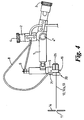
- the present invention avoids the problem of clipping the iris by ensuring that the reflected path 13 of the laser coincides with, or is parallel to, the plane 12 defined by the optical axes 12a of the binocular eyepieces as shown in Figures 4 and 5.
- FIG 4 parts of a conventional indirect ophthalmoscope are allotted the same reference numerals as given in Figure 1.
- a laser attachment 20 is provided secured, (preferably releasably secured, e.g. by screws) to the binocular 5 by a bracket 21. This laser attachment is shown in greater detail in Figures 6 and 7.
- the laser attachment 20 comprises a carrier, or frame, or cage 22 mounted to the bracket 21 in that such a way that it is pivotable about an axis 23 lying in the same plane as the optical axes 12a of the eyepieces 25 (see Figure 2) of the binocular 5 (or more precisely, in the same plane as the optical axes of image - capturing optics (e.g. prisms) of the binoculars - see Figure 10A). That is to say, in Figure 5 the carrier frame 22 is angularly movable about a horizontal axis.
- the carrier 22 defines viewing openings 26 to each side of an optical element 27 in this example a mirror 27, which is carried by the carrier frame 22 and is located in the plane defined by the optical axes 12a, and transverse thereto. That is to say, in Figure 5 the mirror is in a generally vertical plane and is inclined at about 45° to a horizontal line. Laser light is delivered in the viewing plane through optical fibre 8 via focusing lens 28 onto the mirror 27, where it is reflected, still in the viewing plane, along axis 13 to the eye 29 of the patient.
- Journal 21' pivotally mounts the frame 22 to the bracket 21.
- the journal 21 has an adapter 21" which releasably couples an optical fibre 8 to the attachment 20. As the frame 22 moves angularly the fibre 8 remains stationary and aligned with the pivot axis 23 of the frame.
- the central point of the laser directing mirror 27 is provided in a line directly between the eyepieces (or image - capturing optics) of the binoculars.
- the mirror 27 is mounted on a bar, and having to provide a way of moving the bar angularly, the mirror is mounted in the frame 22, and the whole frame 21 is moved angularly. This allows us to put the frame-pivoting and frame manipulating, mechanism outside of the line of sight of the user - laterally outside of the path of light that is gathered by the image -capturing optics of the binoculars. The user looks through the frame, and his line of sight is not impaired as the frame is moved.
- the laser beam reflected from the mirror 27 can truly be co-incident with the central line of sight of the user, instead of being inclined relative to it.
- a mirror indicated at 31 may be provided for reflecting the incoming laser beam into the viewing plane.
- Figure 5' shows a modification in which the mirror 27' is inclined in a direction akin to the prior art, but in which the user still looks through the frame 22', and in which the frame is rotated, carrying the mirror with it, rather than just the mirror. Again, the mirror can reflect a beam of laser light parallel to the plane/line of sight.
- the arrangement of Figure 5 is considered better than that of Figure 5'.
- One reason is because the laser fibre 8 of Figure 5 is on the axis of rotation of the frame 22, and this simplifies the mechanics of coupling the fibre 8 to the frame 22.
- the mirror 27 of Figure 5 is mounted in a vertical plane, that is, a plane normal to the viewing plane, and that this mirror plane is aligned at 45° to the axes 12a of the binocular eyepieces. This allows the central point of the mirror to be located between the viewing eyepieces with no visual obstructions for the clinician.
- the mirror 27 may be rotated for adjustment of the alignment of the axis 13 of the laser beam by pivoting the cage 22 about the axis 23.
- Dichroic filter elements may be fitted to the rear of the cage, or to the eyepieces of the binocular.
- a preferred laser is a KTP laser having a wavelength of 532 nanometres.
- the binocular suitably has a 2x magnification and incorporates the interpupilliary mechanism 19 for adjusting the spacing of the eyepieces 25 to accommodate variations in eye spacing of different users.
- the laser attachment 20 may readily be attached to any conventional indirect ophthalmoscope by its bracket 21, using an intermediate adaptor (not shown) if necessary.
- Laser beam input can be via a conventional optical fibre feed and the attachment 20 may therefore be used for coupling any suitable laser device into such an ophthalmoscope. All that is needed is a suitable connector 21" and an optical fibre 8 (with appropriate connection to connect to the laser).
- the optical fibre 8 suitably also carries a beam of a visible light, for example from a diode light source, which also travels along axis 13 so that the clinician has an aiming marker which will not affect the eye of the patient, but will give an indication of the target point of the laser beam when that is selectively triggered.
- the laser beam is, of course, not normally operating through the indirect ophthalmoscope, only being effectively emitted to the ophthalmoscope, and cutting/burning/sealing, when the clinician activates it.
- the laser will usually be "on” and some stop/shutter mechanism will be opened by the clinician to operate on the eye (typically a foot switch).
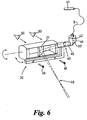
- FIG. 6 shows a finer detail of the arrangement of the attachment 20 of Figure 5.
- a lens 40 of variable focus with the focus controlled by the user (e.g. by a hand-operated wheel or knob).
- a laser 41 is coupled to the attachment via fibre 8.
- a coupling, referenced 42 produces a diverging beam 44 of laser light which is reflected off mirror 30', still diverging at 46.
- the lens 40 focuses the beam of laser light, which is reflected off the mirror 27 to a focal point 48.
- the focal point is intended to be on the retina, or other structure of the patient's eye, to be burned/treated.
- Fixing screws 49 are shown for attaching the attachment 20 to an indirect ophthalmoscope.
- the clinician's eyes are referenced 50.
- Figure 7 shows a mirror carrier 60, carrying a mirror 62 angled at 45° sideways, journalled for angular movement by journal 64, and a hole 66 possibly screw threaded, for receiving a turning lever 68 to enable a user to rotate the carrier 60.
- the lever 68 is normally attached to the carrier 60.
- Our attachment and a laser indirect ophthalmoscopes fitted with it, enables the laser beam to be emitted on the central viewing axis of the binoculars, in the same plane as the binocular plane of sight, rather than being inclined to it. This means that there is less danger of clipping the iris. This in turn means that treatments can be performed faster. Typically a patient is given eye drops to cause their pupil to widen, and a wait is necessary for them to act (perhaps 20 minutes). It is no longer necessary to have the pupil quite so wide in some circumstances using the present invention; and so patients who's pupils are not so dilated can be treated. This can speed up throughput of patients in a clinic/surgery.
- clinicians used the laser mirror control to alter the convergence angle, and convergence distance, of the laser (relative to the plane of the optical axes of the binoculars. Now clinicians alter the laser mirror in order to try to get the laser beam in the plane of the optical axes of the binoculars so that there is no, or substantially no, divergence.
- the laser output mirror is housed within a frame that surrounds, or skirts, the outside of the vision area (the x2 viewing components of the binoculars).
- the laser is introduced laterally (as opposed to vertically as with prior art designs which introduce the laser from above) through a lens, onto the angled 45° output mirror, deflecting the converging beam towards the patient.
- the mounting of the laser-reflecting mirror at about 45°, sideways is an important aspect of one embodiment. In this configuration, with no horizontal tilt mechanism, it allows us to mount the mirror with no visual obstruction and thus making it truly coaxial; this will be a major benefit to the ophthalmologist.
- our attachment fits x2 popular indirects (e.g. the All pupil and Vantage made by Keeler Optical). Unlike other laser attachments which have to be factory integrated our attachment is held on easily by mounting screws. The attachment can be fitted to an existing indirect ophthalmoscope by the user themselves, presenting a big financial saving over integrated laser indirects.
- x2 popular indirects e.g. the All pupil and Vantage made by Keeler Optical.
- Prior art indirect laser headsets are designed by the laser manufacturer and are dedicated to their laser and are not interchangeable with other lasers. Our design allows the user to purchase a product that is not exclusive to any specific laser.
- the laser beam delivered to the mirror is preferably provided in, or substantially in, the plane of view.
- a binocular indirect ophthalmoscope has eyepieces which have optical axes defining a viewing plane. Means is provided for delivering a laser beam in that plane and on the central visual axis of the binoculars. This may be achieved by delivering a laser beam to a reflective surface located between the eyepieces, or in front of the eyepieces, provided for directing the laser beam to be coincident with the viewing axis.
- the cage may be, in some embodiments, adjustable in angle about an axis in the viewing plane and a substantially normal to the central viewing axis. The user looks through or past, a frame that holds the optical element that controls the laser beam, the frame being outside of the user's vision.
- the frame could simply be above or below the apertures.
- the "frame” could simply be a support for the mirror 27, said support being disposed outside of the field of view/plane of view of the binoculars. It will be appreciated that holding the mirror 27 and its upper and/or lower surface, well out of the way of the plane of the field of view, is advantageous.
- the frame/carrier 22 could be bodily linearly moveable (e.g. slidable) or a mixture of sliding and angular movement could be used. What is important is that it is possible to control the "vertical" position of the laser beam without having the control mechanism be in the plane defined by the optical axes of the binoculars, and in the field of view of the clinician.
- control surfaces e.g. levers/wheels/projections
- the mirror is one example of an optical element that can be used to control/direct a laser beam.
- Other optical elements could be used instead of/in addition to a mirror including a prism, and/or a lens.
- the mirror shown in the previous drawings is replaced by a prism.
- the mirror is replaced by an optical fibre delivering a laser beam (or a mounting for an optical fibre to be connected to the carrying frame).
- An optical fibre delivers a divergent beam of light. It would then be desirable to have an optical element, for example a lens, focusing the beam of light. Thus instead of reflecting the beam of light the optical element could simply focus/defocus it.
- the angle of the mirror relative to the laser beam is variable, and can be user-controlled (typically manually controlled), attachments, and ophthalmoscopes, are envisaged in which the mirror/optical element is not movable relative to the attachment/ophthalmoscope- it is reflected at a fixed position. So long as this fixed position is generally on, or very nearly on, the central viewing axis of the binocular ophthalmoscope this will be a good instrument. Having the mirror/optical element movable and being able to control the position of the laser beam enables the user to place the laser beam on the central viewing axis. If it is already on there - because the device has a fixed optical element, and a fixed laser path relative to the optics, and movement of the mirror/optical element may be unnecessary.
- Figure 8 shows an alternative attachment (84) for attaching to an ophthalmoscope.
- This has a mirror 80 (or a prism) mounted on a support (82).
- the direction of the laser beam 88 is shown coming in through the joint 86, and reflecting off the mirror 80.
- the support 82 is outside of the line of vision of the user ophthalmoscope, and does not obstruct the image-gathering optics.
- Figures 9A, 9B, and 9C show different optical elements that can be used to condition or direct a laser beam.
- Figure 9A shows a mirror 90.
- Figure 9B shows a prism 92.
- Figure 9C shows a converging lens 94, and a light-limiting end 96 of an optical fibre 98.
- the optical fibre 98, or its end 96 (or a fitting to receive and locate an optical fibre) is provided in the attachment, along with the focussing lens 94.
- An optical fibre in its diverging beam of light, reference 99, and the lens 94 produces a parallel laser beam, reference 99.
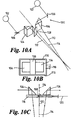
- Figure 10A shows schematically binoculars of an ophthalmoscope 100 having eyepieces 102 through which the clinician looks, image-capturing optical elements 104, in this example prisms, reflecting mirrors 106 which fold the optical path of the light that is gathered/captured by the image-capturing optics 104 and directs it to the eyepieces 102. Also shown schematically is laser-beam deflecting/controlling/conditioning optical element 108 (in this example a mirror). This is disposed, again in this example, slightly in front of the image capturing optics 104 (but it could be level with them, or potentially even within their planned projection.
- image-capturing optical elements 104 in this example prisms
- reflecting mirrors 106 which fold the optical path of the light that is gathered/captured by the image-capturing optics 104 and directs it to the eyepieces 102.
- laser-beam deflecting/controlling/conditioning optical element 108 in this example a mirror. This is disposed, again in this example, slightly in
- Figure 10A also shows the optical axes 110 and 112 of the binoculars, and a central viewing line 114, lying in the plane of the optical axes 110 and 112.
- Figure 10B shows a front view of the arrangement of Figure 10A. Also shown in Figure 10B, but not shown in Figure 10A, is a carrying frame 116 which carries the optical element (e.g. mirror) 108. A spigot 118 is also shown for angularly movably mounting the frame 116.
- the optical element e.g. mirror
- Figure 10C is a plan view of the arrangement of Figures 10A and 10B, also showing a laser beam 120 being reflected off the mirror 108 to be coincident with the central viewing axis 114.
- the image captured by the image capture elements (e.g. prisms) 104 is not impaired by the presence of the mirror 108, nor is it impaired by the frame 116 extending around the outside of the prisms: neither the mirror or the frame is in the projected area of the image capture elements 104 when a point in the field of view is traced back to the image capture elements 104.
- the image capture elements e.g. prisms
- Figure 10D is a front view, similar to that of 10B, showing the image capture elements (prisms) 104 and also showing an area 130 surrounding them which is outside of the path of light that is received by the image capture elements 104, and which is therefore available to contain other useful structures of the attachment/and or ophthalmoscope. It will be appreciated there is no real outer boundary to this area.
- a laser-absorbing structure is preferably provided behind the mirror (or prism) in case the mirror element breaks. It would be undesirable to have the laser come out of the side of the equipment unchecked. For this reason a laser-absorbing structure (e.g. thick metal wall) is provided either directly behind the mirror, or as part of the frame/carrier. For example wall 122 in Figure 5 is typically thick enough to absorb the laser beam without allowing the laser beam to burn through.
- a laser-absorbing structure e.g. thick metal wall
- eyepieces of the binocular ophthalmoscope removable so as to be able to insert different lenses behind the eyepieces.
- eyepiece reference 124 in Figure 1 could unscrew and a different or additional lens could be inserted between the eyepiece and the remainder of the binocular, and the eyepiece then screws back on locating the lens.
- Figure 11 shows an attachment 140 for attaching to the front of a binocular ophthalmoscope.
- a mirror or prism 142 is shown fixedly, non moveably, mounted on mounting beam 144 the mirror is held at its top and bottom edges by a C shaped bracket 146.
- the support beam 144 is releasably attachable to the front of a binocular ophthalmoscope via threaded screw holes 148.
- the device of Figure 11 is not angular moveable about an axis: its orientation relative to the support beam 144 is fixed, and once the support beam 144 has been placed in fixed relationship to the ophthalmoscope to which it is fitted, the angle of the mirror 142 is fixed. So long as when the laser beam falls upon the mirror it is, indeed, reflected generally along the central viewing axis of the binocular ophthalmoscope (and not significantly diverging a above or below the viewing plane, a fixed mirror/optical element arrangement is also envisaged) .
- a modification of the arrangement of Figure 5 could be the fixed mounting of the support frame 22 relative to the carrier 21, there still being a support frame surrounding the mirror, and the clinician still looks through aperture/windows in the support frame.
- the support frame may still surround, preferably completely surround, the apertures/windows through which the clinician looks.
- the advantage of having a support frame is that it is particularly rigid, and can be used to protect the mirror because it extends over its plan area.
- the fact that the support frame has no glass surfaces, other than the mirror, means that there is no glass to break in it, and no glass to become dirty/obscure.
- another variant is envisaged in which there are actual transparent elements in the window/apertures through which the clinician looks - for example glass.
- the support frame for the optical element may circumscribe the optical element, defining one or more window through which the clinician looks in use.
- the optical element may not be a mirror, but could be a lens with a fibre position behind it. The fibre could enter the attachment for the ophthalmoscope at the 12 o'clock, from above, position.
- the concept of a frame carrying the optical element and the frame not getting in the way of the image acquired by the image-capturing optics of the ophthalmoscope is advantageous.
- No other known design enables the laser beam to be delivered from a point that is actually directly the central beaming access of the binoculars, with no accompanying metal work or other material in the field of vision.
- the laser beam may enter the frame that surrounds the mirror through an aperture in the frame.
- Figure 12 shows another modification.
- the divergence of the laser beam as it enters the device is too large to allow us to use a small mirror; we want to use a larger mirror to control it/focus it.
- Figure 12 shows a carrier frame 150, or open-ended box, carrying a larger mirror 152, again with the frame 150 being angularly movable about on axis, referenced 154, for controlling the position of the laser beam on the patients eye.
- the laser beam is referenced 156.
- the mirror 152 extends across the whole length of the frame 150, diagonally from corner 158 to corner 160. In another variant it need not extend across the full internal aperture of the carrier.
- the mirror 150 reflects the laser beam 156, but is transmissive to at least one/some other optical wavelengths, so that the clinician can look through the mirror 152, through the frame 150.
- a dichroic mirror with a reflective, non transmissive, characteristic that covers the laser wavelength will achieve the desired result of having the clinician be able to look through the mirror, supported by the frame; and have the mirror reflect the laser beam, and be larger than in Figures 10A to 10C.
- a further benefit is that because the clinician now looks through the optical element that is supported by the frame, and looks past the frame without the frame reducing the field of view, the dichroic mirror can protect the clinicians eyes from unwanted laser reflections.
- the partially reflective (to laser wavelengths), partially transmissive (to other wavelengths) optical element e.g. mirror, prism, lens, grating or the like
- the partially reflective (to laser wavelengths) optical element e.g. mirror, prism, lens, grating or the like
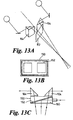
- Figures 13A to 13C are equivalent to Figures 10A to 10C, but for the embodiment of Figure 12. It will be seen that the carrying frame is outside of the field of view of the clinician, and the clinician looks through the frame and the mirror. In some embodiments the mirror/optical element will be pre-set and will not be adjustable, but in many embodiments the frame may be moveable to perform movement of the mirror/optical element.
- the image - capture prisms 104 of Figures 13A to 13C are shown spaced apart, they may be abutting.
- the spacing between the prisms/image capture elements 104 may be adjustable by the clinician.
- the spacing may be adjustable to keep the image capture element within the carrying frame, and either within the mirror (if it is the dichroic filter/reflection), or operatively laterally at least partially beyond the central mirror (if the central mirror does not transmit).
- the frame circumscribes a space through which a user looks in use.
- the mirror is robustly mounted to the frame.
- the mirror may be mounted to the frame substantially completely, or completely, around its periphery.
- the mirror is supported by the frame along substantially the whole of two opposed edges (e.g. upper and lower edges).
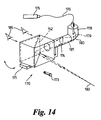
- Figure 14 shows a finer detail of the arrangement of the laser attachment 170 of Figure 12.
- the laser attachment 170 may be readily attached to any conventional indirect ophthalmoscope by way of a bracket 171, and fixed in place by fixing screws 173.
- a lens 174 of variable focus with focus controlled by the user.
- a laser 175 is coupled to the attachment 170 via fibre 177.
- a coupling, referenced 178, produces a diverging beam 179 of laser light which is reflected off mirror 180, still diverging at 181.
- the lens 174 focuses the beam of laser light which is reflected off the mirror 152 to a focal point 183.
- the focal point is intended to be the retina, or other structure of the patient's eyes, to be burned/treated.
- the clinician's eyes are referenced 185.
- a dichroic mirror can impart a slight colour to the image observed through the mirror, it is therefore preferable that the mirror 152 fills the users entire field of view, such that the image seen is evenly discoloured. If the edge of the mirror 152 can be seen in the users field of view a contrast in colour may be seen which may impede the users vision.
- Figure 15 shows a mirror carrier 190 carrying a mirror 192 angled at 45° sideways, journalled for angular movement by journal 194, and a hole 196 possibly screw threaded, for receiving a turning lever 198 to enable a user to rotate the carrier 190.
- the lever 198 is normally attached to the carrier 190.
- the mirror carrier is configured as a cube in which all sides are approximately 20mm, and the journal 194 has a diameter of approximately 11mm.
Landscapes
- Life Sciences & Earth Sciences (AREA)
- Health & Medical Sciences (AREA)
- Medical Informatics (AREA)
- Biophysics (AREA)
- Ophthalmology & Optometry (AREA)
- Engineering & Computer Science (AREA)
- Biomedical Technology (AREA)
- Heart & Thoracic Surgery (AREA)
- Physics & Mathematics (AREA)
- Molecular Biology (AREA)
- Surgery (AREA)
- Animal Behavior & Ethology (AREA)
- General Health & Medical Sciences (AREA)
- Public Health (AREA)
- Veterinary Medicine (AREA)
- Laser Surgery Devices (AREA)
- Telescopes (AREA)
Applications Claiming Priority (3)
| Application Number | Priority Date | Filing Date | Title |
|---|---|---|---|
| GB0216374A GB2376634B (en) | 2002-07-13 | 2002-07-13 | Laser accessory for a binocular indirect ophthalmoscope and binocular indirect ophthalmoscope |
| GB0216374 | 2002-07-13 | ||
| US10/207,372 US6830335B2 (en) | 2002-07-13 | 2002-07-29 | Ophthalmoscope laser attachment |
Publications (2)
| Publication Number | Publication Date |
|---|---|
| EP1380252A2 true EP1380252A2 (de) | 2004-01-14 |
| EP1380252A3 EP1380252A3 (de) | 2004-04-21 |
Family
ID=32395872
Family Applications (1)
| Application Number | Title | Priority Date | Filing Date |
|---|---|---|---|
| EP03252663A Withdrawn EP1380252A3 (de) | 2002-07-13 | 2003-04-26 | Binokulares Ophthalmoskop mit indirektem Laser |
Country Status (3)
| Country | Link |
|---|---|
| US (1) | US6830335B2 (de) |
| EP (1) | EP1380252A3 (de) |
| GB (1) | GB2376634B (de) |
Families Citing this family (5)
| Publication number | Priority date | Publication date | Assignee | Title |
|---|---|---|---|---|
| JP4492845B2 (ja) * | 2003-10-14 | 2010-06-30 | 株式会社ニデック | レ−ザ治療装置 |
| US20070121069A1 (en) | 2005-11-16 | 2007-05-31 | Andersen Dan E | Multiple spot photomedical treatment using a laser indirect ophthalmoscope |
| JP2016064539A (ja) * | 2014-09-24 | 2016-04-28 | 株式会社ミマキエンジニアリング | 立体物造形装置及び立体物造形方法 |
| CN113367655B (zh) * | 2021-06-09 | 2022-06-10 | 赣南医学院第一附属医院 | 一种基于裂隙灯平台的眼科多功能眼前段成像装置 |
| EP4382034B1 (de) * | 2022-12-05 | 2026-03-18 | Optos plc | Spiegelausrichtungsmechanismus für ophthalmische bildgebungssysteme |
Family Cites Families (19)
| Publication number | Priority date | Publication date | Assignee | Title |
|---|---|---|---|---|
| DE3045139A1 (de) * | 1980-11-29 | 1982-07-01 | Fa. Carl Zeiss, 7920 Heidenheim | Vorrichtung zur subjektiven und objektiven refraktionsbestimmung |
| US4397310A (en) | 1981-02-27 | 1983-08-09 | The Government Of The United States Of America As Represented By The Secretary Of Department Of Health And Human Services | Anastigmatic high magnification, wide-angle binocular indirect attachment for laser photocoagulator |
| JPS5953005U (ja) * | 1982-09-28 | 1984-04-07 | 旭光学工業株式会社 | 撮影装置付検眼鏡の照明光軸調節機構 |
| DE3335810A1 (de) * | 1983-10-01 | 1985-04-18 | Fa. Carl Zeiss, 7920 Heidenheim | Optisches system fuer therapeutische laserlichtanwendung |
| US4580559A (en) * | 1984-07-24 | 1986-04-08 | Esperance Francis A L | Indirect ophthalmoscopic photocoagulation delivery system for retinal surgery |
| US4669837A (en) * | 1984-10-24 | 1987-06-02 | Kurt E. Schirmer | Ophthalmoscope with laser photocoagulator |
| US4614411A (en) * | 1985-05-16 | 1986-09-30 | Carl-Zeiss-Stiftung, Heidenheim/Brenz | Microscope with correlatable fixation target |
| JP3165144B2 (ja) * | 1990-10-26 | 2001-05-14 | 株式会社ニデック | 双眼倒像鏡式レーザ治療装置 |
| JP2965101B2 (ja) * | 1992-07-31 | 1999-10-18 | 株式会社ニデック | 眼科装置 |
| US5479222A (en) | 1993-11-15 | 1995-12-26 | Volk; Donald A. | Indirect ophthalmoscopy lens system and adapter lenses |
| US5805269A (en) | 1996-08-27 | 1998-09-08 | Volk Optical, Inc. | High magnification indirect ophthalmoscopy lens device |
| US5784148A (en) * | 1996-04-09 | 1998-07-21 | Heacock; Gregory Lee | Wide field of view scanning laser ophthalmoscope |
| US5817088A (en) * | 1997-02-10 | 1998-10-06 | Nidek Incorporated | Laser indirect ophthalmoscope |
| US5940166A (en) * | 1997-09-12 | 1999-08-17 | Miller; Joel A. | Binocular indirect ophthalmoscope |
| GB9819715D0 (en) | 1998-09-11 | 1998-11-04 | Keeler Ltd | Opthalmoscope and attachment therefor |
| GB9819714D0 (en) * | 1998-09-11 | 1998-11-04 | Keeler Ltd | Ophthalmoscope and image detection means therefor |
| US6186628B1 (en) | 1999-05-23 | 2001-02-13 | Jozek F. Van de Velde | Scanning laser ophthalmoscope for selective therapeutic laser |
| US6280033B1 (en) | 2000-03-08 | 2001-08-28 | Keeler Limited | Indirect ophthalmoscope |
| DE10025843A1 (de) | 2000-05-23 | 2001-12-13 | Zeiss Carl Jena Gmbh | Adapter für ophthalmologische Geräte |
-
2002
- 2002-07-13 GB GB0216374A patent/GB2376634B/en not_active Expired - Fee Related
- 2002-07-29 US US10/207,372 patent/US6830335B2/en not_active Expired - Fee Related
-
2003
- 2003-04-26 EP EP03252663A patent/EP1380252A3/de not_active Withdrawn
Also Published As
| Publication number | Publication date |
|---|---|
| GB0216374D0 (en) | 2002-08-21 |
| GB2376634A (en) | 2002-12-24 |
| GB2376634B (en) | 2003-12-10 |
| EP1380252A3 (de) | 2004-04-21 |
| US20040017545A1 (en) | 2004-01-29 |
| US6830335B2 (en) | 2004-12-14 |
Similar Documents
| Publication | Publication Date | Title |
|---|---|---|
| US5413555A (en) | Laser delivery system | |
| JP3206923B2 (ja) | 眼科用レーザ手術装置 | |
| JP7014450B2 (ja) | 反射ミラーを備える治療用レーザ | |
| JP3165144B2 (ja) | 双眼倒像鏡式レーザ治療装置 | |
| US4477159A (en) | Photocoagulator | |
| US7252661B2 (en) | Method and system for patient optical fixation | |
| JP3008359B2 (ja) | 手術用顕微鏡の照明手段 | |
| EP1905349B1 (de) | Spaltlampenmikroskop und ophthalmische Laserbehandlungsvorrichtung mit eingebautem Spaltlampenmikroskop | |
| US4573467A (en) | Optical coupling device for biomicroscope | |
| JP7048156B2 (ja) | 反射ミラーと、安全インターロックとを備える治療用レーザ | |
| US4776335A (en) | Laser spot projector | |
| US4759360A (en) | Laser coagulation system | |
| EP0485450A1 (de) | Vorrichtung für photokoagulation | |
| US4520824A (en) | Instrument for ophthalmic laser surgery | |
| EP1377243B1 (de) | Ophthalmisches lasersystem | |
| JP2003177327A (ja) | ステレオ手術顕微鏡の0°照明及び斜照明を同時に行うためのプリズム構造体 | |
| US6830335B2 (en) | Ophthalmoscope laser attachment | |
| US5817088A (en) | Laser indirect ophthalmoscope | |
| US5155509A (en) | Oblique illumination device for use with an ophthalmic microscope | |
| US6208460B1 (en) | Optical head | |
| JP4054538B2 (ja) | レーザ治療装置 | |
| US6280033B1 (en) | Indirect ophthalmoscope | |
| JP2004033277A (ja) | 眼科装置及びこれを備えるレーザ治療装置 | |
| JP2021023542A (ja) | 眼科装置 | |
| AU750854B2 (en) | Optical head |
Legal Events
| Date | Code | Title | Description |
|---|---|---|---|
| PUAI | Public reference made under article 153(3) epc to a published international application that has entered the european phase |
Free format text: ORIGINAL CODE: 0009012 |
|
| AK | Designated contracting states |
Kind code of ref document: A2 Designated state(s): AT BE BG CH CY CZ DE DK EE ES FI FR GB GR HU IE IT LI LU MC NL PT RO SE SI SK TR |
|
| AX | Request for extension of the european patent |
Extension state: AL LT LV MK |
|
| PUAL | Search report despatched |
Free format text: ORIGINAL CODE: 0009013 |
|
| RIN1 | Information on inventor provided before grant (corrected) |
Inventor name: SNELLGROVE, TIMOTHY RALPH Inventor name: GUTRIDGE, JOHN ROBERT |
|
| AK | Designated contracting states |
Kind code of ref document: A3 Designated state(s): AT BE BG CH CY CZ DE DK EE ES FI FR GB GR HU IE IT LI LU MC NL PT RO SE SI SK TR |
|
| AX | Request for extension of the european patent |
Extension state: AL LT LV MK |
|
| AKX | Designation fees paid | ||
| REG | Reference to a national code |
Ref country code: DE Ref legal event code: 8566 |
|
| STAA | Information on the status of an ep patent application or granted ep patent |
Free format text: STATUS: THE APPLICATION IS DEEMED TO BE WITHDRAWN |
|
| 18D | Application deemed to be withdrawn |
Effective date: 20041022 |