EP1380330A1 - Dispositif de traitement des eaux de pluie dans des eaux d'egout mixtes et procede de lavage a contre-courant associe - Google Patents
Dispositif de traitement des eaux de pluie dans des eaux d'egout mixtes et procede de lavage a contre-courant associe Download PDFInfo
- Publication number
- EP1380330A1 EP1380330A1 EP02714472A EP02714472A EP1380330A1 EP 1380330 A1 EP1380330 A1 EP 1380330A1 EP 02714472 A EP02714472 A EP 02714472A EP 02714472 A EP02714472 A EP 02714472A EP 1380330 A1 EP1380330 A1 EP 1380330A1
- Authority
- EP
- European Patent Office
- Prior art keywords
- rainwater
- sewer
- treating
- vessel
- treated water
- Prior art date
- Legal status (The legal status is an assumption and is not a legal conclusion. Google has not performed a legal analysis and makes no representation as to the accuracy of the status listed.)
- Granted
Links
Images



Classifications
-
- B—PERFORMING OPERATIONS; TRANSPORTING
- B01—PHYSICAL OR CHEMICAL PROCESSES OR APPARATUS IN GENERAL
- B01D—SEPARATION
- B01D24/00—Filters comprising loose filtering material, i.e. filtering material without any binder between the individual particles or fibres thereof
- B01D24/002—Filters comprising loose filtering material, i.e. filtering material without any binder between the individual particles or fibres thereof with multiple filtering elements in parallel connection
- B01D24/005—Filters being divided into a plurality of cells or compartments
-
- B—PERFORMING OPERATIONS; TRANSPORTING
- B01—PHYSICAL OR CHEMICAL PROCESSES OR APPARATUS IN GENERAL
- B01D—SEPARATION
- B01D24/00—Filters comprising loose filtering material, i.e. filtering material without any binder between the individual particles or fibres thereof
- B01D24/02—Filters comprising loose filtering material, i.e. filtering material without any binder between the individual particles or fibres thereof with the filter bed stationary during the filtration
- B01D24/20—Filters comprising loose filtering material, i.e. filtering material without any binder between the individual particles or fibres thereof with the filter bed stationary during the filtration the filtering material being provided in an open container
- B01D24/26—Upward filtration
- B01D24/263—Upward filtration the filtering material being supported by pervious surfaces
-
- Y—GENERAL TAGGING OF NEW TECHNOLOGICAL DEVELOPMENTS; GENERAL TAGGING OF CROSS-SECTIONAL TECHNOLOGIES SPANNING OVER SEVERAL SECTIONS OF THE IPC; TECHNICAL SUBJECTS COVERED BY FORMER USPC CROSS-REFERENCE ART COLLECTIONS [XRACs] AND DIGESTS
- Y10—TECHNICAL SUBJECTS COVERED BY FORMER USPC
- Y10S—TECHNICAL SUBJECTS COVERED BY FORMER USPC CROSS-REFERENCE ART COLLECTIONS [XRACs] AND DIGESTS
- Y10S210/00—Liquid purification or separation
- Y10S210/918—Miscellaneous specific techniques
- Y10S210/919—Miscellaneous specific techniques using combined systems by merging parallel diverse waste systems
-
- Y—GENERAL TAGGING OF NEW TECHNOLOGICAL DEVELOPMENTS; GENERAL TAGGING OF CROSS-SECTIONAL TECHNOLOGIES SPANNING OVER SEVERAL SECTIONS OF THE IPC; TECHNICAL SUBJECTS COVERED BY FORMER USPC CROSS-REFERENCE ART COLLECTIONS [XRACs] AND DIGESTS
- Y10—TECHNICAL SUBJECTS COVERED BY FORMER USPC
- Y10S—TECHNICAL SUBJECTS COVERED BY FORMER USPC CROSS-REFERENCE ART COLLECTIONS [XRACs] AND DIGESTS
- Y10S210/00—Liquid purification or separation
- Y10S210/918—Miscellaneous specific techniques
- Y10S210/92—Miscellaneous specific techniques using combined systems of sequential local and regional or municipal sewage systems
-
- Y—GENERAL TAGGING OF NEW TECHNOLOGICAL DEVELOPMENTS; GENERAL TAGGING OF CROSS-SECTIONAL TECHNOLOGIES SPANNING OVER SEVERAL SECTIONS OF THE IPC; TECHNICAL SUBJECTS COVERED BY FORMER USPC CROSS-REFERENCE ART COLLECTIONS [XRACs] AND DIGESTS
- Y10—TECHNICAL SUBJECTS COVERED BY FORMER USPC
- Y10S—TECHNICAL SUBJECTS COVERED BY FORMER USPC CROSS-REFERENCE ART COLLECTIONS [XRACs] AND DIGESTS
- Y10S210/00—Liquid purification or separation
- Y10S210/918—Miscellaneous specific techniques
- Y10S210/921—Flow equalization or time controlled stages or cycles
Definitions
- the present invention relates to a rainwater-treating apparatus in a combined sewer system into which wastewater and storm water are combined as a sewer in a confluent flow.
- the invention also relates to a method for back washing said apparatus.
- the invention further relates to a sewer-treating system which uses the sewer-treating apparatus in raining (hereinafter referred to as "rainwater-treating apparatus).
- drainwater-treating apparatus the term "rainwater” is used to mean the sewer which is the combined flow of the storm water and the wastewater during raining, therefore "rainwater” as a common meaning is discriminated from "storm water”.
- the flow amount largely varies between non-rainy weather and rainfall weather.
- the maximum inflow water amount per hour into the sewer-treating plant during raining is controlled to three times 3Q as much as a design water amount Q that is the maximum inflow water amount per hour when there is no storm water.
- An ordinary treatment can be effected in the same manner as in non-rainy weather if the water amount does not exceed Q. However, if it is more than Q and not more than 3Q, this exceeds the ordinary treating power of the reaction vessel in the treating plant, and therefore a simple treatment is effected in which the rainwater is subjected to settlement treatment in the first sedimentation basin and then discharged. Further, if the water amount increases and exceeds 3Q, the stormwater is actually discharged directly to a river, etc. without being treated at all.
- the apparatus is equipped with a flocculant-feeding mechanism to increase the treating efficiency.
- a civil equipment such as an existing first sedimentation basin, having a water depth of 2.5 to 4 m cannot be used, the above filter apparatus is a technique that is required to be newly constructed from a civil structure, resulting in a huge cost required.
- the present invention solves the above problems of the prior art, and has been made to provide a rainwater-treating apparatus in the combined sewer system which apparatus can remove a majority of the pollution substances even if rainwater exceeding Q enters or much rainwater. exceeding 3Q enter. Further, the present invention provides a rainwater-treating apparatus which can be installed inexpensively by easily modifying an existing first sedimentation basin as well as a method for back washing the apparatus. Other object of the present invention is to provide the rainwater-treating apparatus in the combined sewer system and the back washing method therefor, enabling the accomplishment of the above object with almost no need of maintenance.
- the present invention is made to solve the above problems, and its first aspect is to provide a rainwater-treating apparatus in a combined sewer system, said apparatus comprising a plurality of upward flow type high-speed filter vessels each having a layer of a floating filter medium, a common treated water vessel which is located at upper faces of said high-speed filter vessels and is adapted to collect treated water from the high-speed filter vessels, a used wash water vessel which collects used wash water from said high-speed filter vessels, a rainwater inflow channel for distributing the entering rainwater into upper portions of the high speed filter vessels, and rainwater inflow portions for flowing downwardly the rainwater distributed from the rainwater inflow channel under the respective floating filter media of the filter vessels.
- the rainwater-treating apparatus according to the present invention can be constructed by partitioning a first sedimentation basin in the conventional combined flow type sewer-treating plant.
- a second aspect of the present invention is to provide a sewer-treating system in a combined flow type sewer-treating line, said system comprising a first sewer-treating section and a second sewer-treating section, said first sewer-treating section comprising a sand-settling basin for receiving sewer, a first sedimentation basin provided downstream of the sand-settling basin and a reacting vessel provided downstream of the sedimentation basin, said second sewer-treating section being provided downstream of the sand-settling basin and comprising a plurality of upward flow type high-speed filter vessels each having a layer of a floating filter medium, a common treated water vessel which is located at upper faces of said high-speed filter vessels and is adapted to collect treated water from the high-speed filter vessels, a used wash water vessel which collects used wash water from said high-speed filter vessels, a rainwater inflow channel for distributing the entering rainwater into upper portions of the high speed filter vessels, and rainwater inflow portions for flowing downwardly the rainwater distributed from the rainwater inflow channel under the respective floating filter media
- the rainwater-treating apparatus can be installed by modifying the existing first sedimentation basin having a height of 2.5-4 m, for example.
- the reason is as follows. That is, finer filter medium particles are used as compared with the conventional apparatus, the thickness of the floating filter medium layer can be made as thin as around 0.5 to 1 m that is less than 2 m, no lower screen is required, and that an equipment for adding a flocculant is necessary. Consequently, the compact high-speed filter apparatus can be accomplished, and a plurality of the high-speed filter vessels are provided to reduce an amount of wash water to be used at one time, thereby the thickness of the common treated water vessel can be made thin. Further, the rainwater inflow channel preferably distributes the rainwater as a spontaneous falling flow into the rainwater inflow portions of the respective high-speed filter vessels via inflow weirs of the channel so that variations in the water amount may be coped with.
- back washing is effected with respect to any high-speed filter vessel in the rainwater-treating apparatus which filter vessel increased its preset pressure loss by flowing downwardly the treated water in the common treated water vessel through the high-speed filtering vessel.
- the upwardly flowing type high-speed filter vessels are provided through partitioning the first sedimentation basin in the combined flow type sewer-treating plant, and a large amount of the rainwater flowing in during raining is distributed into the vessels through the rainwater inflow channel, so that the rainwater can be filtered at a high speed with the charged floating filter medium. Therefore, even if the rainwater enters in an amount of more than Q or if a large amount of the rainwater enters in an amount exceeding 3Q, a majority of the pollution substances can be removed. Furthermore, since the high-speed filter vessels and so forth are provided through partitioning a part of the existing first sedimentation basins, a space for constructing and installing a new civil equipment is not required to be ensured. As explained below in more detail, the apparatus can be operated in the present invention with almost no maintenance.
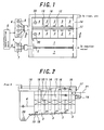
- Fig. 1 is a plane view of the rainwater-treating apparatus according to the present invention
- Fig. 2 is a sectional view of Fig. 1 cut along a line II-II.
- a necessary portion of conventional first sedimentation basins 1 provided in the combined flow type sewer-treating plant are left as they are (in the drawings, two rows are used as the first sedimentation basins), a plurality of high-speed filter vessels 3 and used wash water vessels 4 are formed in the remainder (in the drawings, two rows of the high-speed filter vessels and the used wash water vessels).
- the water area of the first sedimentation basins 1 decreases as compared with that in the conventional case.
- the smaller water area of the first sedimentation basins 1 is recently sufficient with progress in the sewer-treatment technology as compared with the conventional case. Accordingly, in the combined flow type sewer-treating plants, the treating powers of the first sedimentation basins 1 are often not fully used. Thus, the invention arrangement makes no affect upon the ordinary sewer treatment. It may be said that since the first sedimentation basins receive only up to the maximum sewer amount per hour during non-rainy weather, there is no influence upon the ordinary sewer treatment.
- a sand-settling basin 5 for receiving sewer and a rainwater vessel 6 and a wastewater vessel 7 into which sewer is distributed from the sand-settling basin, depending upon a design water amount and a rail falling amount.
- the rainwater vessel 6 and the wastewater vessel 7 are combined in the form of a common vessel.
- entering sewer is entirely received in the sedimentation basin 5, and up to the design water amount 3Q is led to the conventional first sedimentation basins 1 by wastewater pumps 8.
- Water from which suspended substances (SS) are separated in the first sedimentation basins 1 is led to a downstream reaction vessel where water is treated as conventionally.
- the entering amount of water is not more than Q, the above line only is operated in the same manner as in the conventional case.
- the amount of the flowing-in water sometimes exceeds Q during raining, a portion of the water exceeding Q is entirely led to of the high-speed filter vessels 3. Therefore, water feed pipes from the wastewater pumps 8 are modified to be led to the high-speed filter vessels 3, if necessary.
- the high-speed filter vessel 3 is a filter vessel in which a screen 10 is stretched in a middle portion and a floating filter medium 11 is charged under the screen 10.
- totally eight filter vessels are arranged in two rows, but the number of the vessels is arbitrary, although plural is necessary.
- These high-speed filter vessels 3 are upwardly flowing type filter vessels.
- a vertical rainwater inflow portion 12 is provided for each filter vessel. Rainwater is fed to a lower portion of the vessel through the rainwater inflow portion 12, and inclusions and SS are captured and the treated water discharged upwardly, while the sewer upwardly passes a layer the floating filter medium 11 charged.
- a common treated water vessel 13 is provided at upper faces of the high-speed filter vessels.
- the treated water flows in the treated rainwater channel 14 from an end of the common treated water vessel 13 (from a right end portion in the drawings, and then discharged to a river, etc.
- each four filter vessels are connected to a single common treated water vessel 13. Since a simple treated water bypass water discharge path is provided at an outflow portion of the usual first sedimentation basins, the discharge path can be modified into the treated rainwater water channels.
- a rainwater inflow channel 15 is provided above the high-speed filter vessels 3 to distribute rainwater into the above-mentioned rainwater inflow portions 12.
- the rainwater inflow channel 15 is arranged at such a high position to ensure a water level corresponding to a loss water head.
- inflow weirs of the rainwater inflow channel 15 are set higher than the water surface of the common treated water vessel 13 by around 0.2 to 1 mm.
- the filter loss water head can be set higher within this range.
- treatment is effected for a long time period during no rainy weather after raining, it can be set lower in this range.
- Rainwater is raised into the rainwater inflow channel 15 with the above rainwater pumps 8 and if necessary the wastewater pump 8, and is distributed and spontaneously flown down into the rainwater inflow portions 12 of the high-speed filter vessels 3 via the inflow weirs 16 provided in the rainwater inflow channel 15.
- a rainwater bypass gate 17 is preferably provided in a terminal end, for example of the rainwater inflow channel 15 to overflow excess rainwater. Excess rainwater is flown down into the treated rainwater channel 14, and is discharged directly to the river or the like.
- the rainwater bypass gate 17 may be preliminarily set at an arbitrary height.
- the floating filter medium 11 to be used in the present invention is made preferably of a foamed polymer having an apparent density of 0.1 to 0.4, a 50% compression hardness of not less than 0.1 MPa.
- a foamed polymer having such physical properties polypropylene, polystyrene, polyethylene, etc. may be recited.
- closed cell type foamed polyethylene having the foamed degree controlled is preferred from the standpoint of heat resistance, chemical resistance and weather resistance.
- the apparent density of the floating filter medium 11 is less than 0.1, a desirable compression hardness cannot be obtained and the charged layer of the floating filter medium is difficult to swell on back washing. On the other hand, if it is more than 0.4, it is feared that the filter medium may be downwardly flown away on back washing. Further, if the 50% compression hardness is less than 0.1 MPa, the filter medium is compacted on filtering at a high speed, so that a large amount of SS cannot be captured.
- the 50% compression hardness means a pressure required to crush the filter medium to a half of its height.
- the floating filter medium 11 to be used in the present invention is preliminarily constituted by filter medium pieces having sizes of 4 to 10 mm with uneven shapes or cylindrical shapes.
- the uneven shape means not a simple shape such as cubic or sphere but strange shape having some uneven portions at its outer surface.
- the floating medium pieces 11 having such uneven shapes have the advantage that they form non-linear large gaps among them, so that a large amount of SS can be captured. Further, the floating filter medium pieces 11 having cylindrical or columnar shapes also have the advantage that they can capture a large amount of SS.
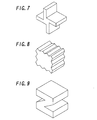
- Figs. 7 to 11 illustrate filter medium pieces to be used in the present invention by way of example.
- Fig. 7 shows a filter medium piece having four plate-like arms 9.
- Fig. 8 shows a filter medium piece in which wavy uneven portions are formed around an outer peripheral surface of a planar body having a rectangular sectional shape.
- Fig. 9 shows a filter medium piece having a Z-like sectional shape.
- Fig. 10 shows a tubular filter medium piece.
- Fig. 11 shows a wind wheel-type filter medium piece formed by modifying the blade portions of Fig. 7.
- the size of the floating filter medium piece 11 is smaller than 4 mm, it is likely to cause clogging, and unsuitable for high-speed filtering. If it is larger than 10 mm, the capturing efficiency of SS decreases.
- the size in the case of strange-shape floating filter medium piece 11 means the maximum outer diametrical dimension. In addition to the above mentioned floating filter medium pieces 11, spherical filter medium pieces having a smaller apparent density can be charged.
- the high-speed filter vessel 3 in which such floating filter medium pieces 11 are charged can capture a large amount of SS, free from compacting of the filter medium, so that a large amount of the rainwater can be treated at high speed.
- a used wash water discharge valve 18 is provided in a bottom portion of each high-speed filter vessel 3 so that water in a lower portion of the vessel may be discharged into the used wash water vessel 4 via a used wash water pipe 19.
- a water discharge pump 20 provided in the used wash water vessel 4 leads the used wash water to a wastewater flow-in channel 22 or into the conventional first sedimentation basins 1, as shown in Fig. 1, where the used wash water is treated.
- the used wash water valve 18 is used, but the used wash water may be discharged by a siphon type water discharge path without using the used wash water valve 18.
- the high-speed filter vessels 3 in the present apparatus can be washed with a secondary treated water (secondary treated water : water which has been treated in the reaction vessel) in the sewer-treating plant so as to prevent generation of offensive odors on stoppage.
- a secondary treated water feed pipe 21 is provided to feed the secondary treated water into the common treated water vessel.
- the combined sewer amount flowing in the sand-settling vessel 5 exceeds the design water amount Q when it starts raining, an excess portion of the rainwater is entirely raised to the rainwater inflow channel 15 by the rainwater pumps 9 and if necessary the wastewater pumps 8. Then, the excess water spontaneously flows down and is distributed into the rainwater inflow portions 12 of the respective high-speed filter vessels 3 via the inflow weirs 16 as shown in Fig. 4. The distributed rainwater once flows down under the filter medium layer, and then upwardly flows and is filtered through the filter medium layer of the high-speed filter vessel 3, and the treated water is discharged to the river, etc. via the common treated water vessel 13 and the treated rainwater channel 14.
- the rainwater-treating apparatus can filter a large amount of the rainwater at a high speed. Even if the amount of rainwater varies, a portion of the water exceeding the design water amount Q can be entirely filtered depending upon variations in the variations in rainwater, unless the amount of entering water abnormally increases. Since the SS removal percentage of the high-speed filter vessel in the present invention is about 70%, a majority of the pollution substances can be removed different from the conventional case even if a large amount of rainwater enters exceeding 3Q.
- Fig. 5 illustrates this state by way of example wherein the pressure loss of the ultra left side increases and the water level of the rainwater inflow portion 12 conspicuously increases as compared with the other vessels.
- the pressure loss of all the high-speed filter vessels 3 gradually increases and cannot effect filtering sooner or later.
- the high-speed filter vessels 3 are successively back washed when they reach the pressure loss representing the above-mentioned automatically washing timing.
- back washing is effected by opening the used wash water valve 18 in the bottom portion and downwardly flowing the treated water in the common treated water vessel 13.
- Fig. 6 shows this state in which the ultra left vessel is under back washing.
- the floating filter medium 11 having the apparent density of 0.1 to 0.4 is used for example, the filter medium can be effectively prevented from being discharged together with the back wash water.
- the back wash water enters the used back wash water vessel 4, and the water discharge pump 20 leads the used wash water to the conventional wastewater inflow channel 2 or the first sedimentation basins 1 for treating it.
- back washing is spontaneously effected only by opening the used wash water valve 18 without operating any washing pump, etc.
- rainwater continuously flows in through the rainwater inflow portion 12, and high-speed filtering is continued in the high-speed filer vessels other than that under washing, so that the treated water is always fed into the common treated water vessel 13.
- the time required for back washing one vessel depends upon the thickness of the filter medium, around 1 to 2 minutes are required for the thickness of the filter medium being 0.5 to 1 m.
- the second vessel from the ultra left vessel which is under washing, reaches the back washing timing, although unusually.
- the second vessel from the left side is waiting for washing until the ultra left vessel finishes washing and the water level of the common treated water vessel 13 reaches a preset level.
- the water level of the rainwater inflow portion 12 may become the same as that of the rainwater inflow channel 15 at the maximum due to further increase in pressure loss.
- the moving amount of the water into the rainwater inflow portion from the rainwater inflow channel 15 decreases as compared with that in the other vessels.
- the decreased amount of water enters the rainwater inflow portions 12 of the other vessels, and is treated there. Therefore, even if the back wash timing happens to overlap like this, completely no maintenance managing control is effected regarding the operation of introduction of the rainwater. Further, the washing time is around 2 minutes as mentioned above in the present invention, the washing-waiting time causes no actual problem.
- the secondary treated water in the sewer-treating plant is fed into the common treated water vessel 13 via the secondary treated water feed pipe 21 so that the high speed filter vessels 3 are separately and successively back washed.
- the used wash water valve 18 is opened to completely wash an arbitrary one high-speed filter vessel 3.
- all the high-speed filter vessels 3 are completely washed. Since this washing completely washes the filter media with use of the secondary treated water different from the above-mentioned filtration on rainy weather, the high-speed filter vessels wait for next inflow of rainwater.
- the rainwater-treating apparatus in the combined sewer system and the sewer-treating system using this rainwater-treating apparatus according to the present invention almost all inflow rainwater exceeding Q which has formerly simply treated or not treated can be filtered, which can contributes the environmental clarification of the rivers, etc. Further, since the rainwater-treating apparatus of the present invention can be provided by partitioning the first sedimentation basin in the combined flow type sewer-treating plant, a space for constructing and installing a new civil equipment is advantageously not required to be ensured. Further, the rainwater-treating apparatus according to the present invention is almost free from maintenance, and the flow rate can be spontaneously effected without requiring operation which a worker must do particularly depending upon changes in rain amount during storming.
- each high-speed filter vessel can be back washed by utilizing the treated water in the common treated water vessel without stopping the operation of the entire apparatus, while generation of offensive odors, etc. are completely prevented.
- the present invention relates to the rainwater-treating apparatus to be used for treating sewer in the combined sewer system for sewer and storm water and also to the sewer-treating system using this rainwater-treating apparatus.
- the invention can ensure the treatment of the sewer in the combined sewer systems which have been recently increasing.
- the invention has great industrial applicability in contributing the environmental clarification for rivers, etc.
Landscapes
- Chemical & Material Sciences (AREA)
- Chemical Kinetics & Catalysis (AREA)
- Filtration Of Liquid (AREA)
- Sewage (AREA)
Applications Claiming Priority (3)
| Application Number | Priority Date | Filing Date | Title |
|---|---|---|---|
| JP2001105637 | 2001-04-04 | ||
| JP2001105637 | 2001-04-04 | ||
| PCT/JP2002/003404 WO2002081050A1 (fr) | 2001-04-04 | 2002-04-04 | Dispositif de traitement des eaux de pluie dans des eaux d'egout mixtes et procede de lavage a contre-courant associe |
Publications (3)
| Publication Number | Publication Date |
|---|---|
| EP1380330A1 true EP1380330A1 (fr) | 2004-01-14 |
| EP1380330A4 EP1380330A4 (fr) | 2004-12-08 |
| EP1380330B1 EP1380330B1 (fr) | 2008-06-04 |
Family
ID=18958292
Family Applications (1)
| Application Number | Title | Priority Date | Filing Date |
|---|---|---|---|
| EP02714472A Expired - Lifetime EP1380330B1 (fr) | 2001-04-04 | 2002-04-04 | Dispositif de traitement des eaux de pluie dans des eaux d'egout mixtes et procede de lavage a contre-courant associe |
Country Status (5)
| Country | Link |
|---|---|
| US (1) | US6821445B2 (fr) |
| EP (1) | EP1380330B1 (fr) |
| JP (1) | JP3824583B2 (fr) |
| DE (1) | DE60226965D1 (fr) |
| WO (1) | WO2002081050A1 (fr) |
Cited By (2)
| Publication number | Priority date | Publication date | Assignee | Title |
|---|---|---|---|---|
| WO2013151196A1 (fr) * | 2012-04-06 | 2013-10-10 | 주식회사 부강테크 | Appareil de traitement des eaux usées capable d'effectuer à la fois le traitement initial du surplus d'eaux de pluie et le traitement principal, et méthode de traitement des eaux usées grâce audit appareil |
| CN108744709A (zh) * | 2018-06-29 | 2018-11-06 | 苏州市奇捷生物科技有限公司 | 一种新型工业废水处理池 |
Families Citing this family (26)
| Publication number | Priority date | Publication date | Assignee | Title |
|---|---|---|---|---|
| AUPS253102A0 (en) * | 2002-05-23 | 2002-06-13 | Unisearch Limited | Oil from water separation system |
| DE20103875U1 (de) * | 2001-03-07 | 2001-08-16 | Vollmar Gmbh | Abwasseranlage mit Reinigungsvorrichtung |
| US7052206B1 (en) * | 2003-04-30 | 2006-05-30 | Mastromonaco Ralph G | System and method for use of an extention basin as a storm water control device |
| JP2005218991A (ja) * | 2004-02-06 | 2005-08-18 | Unitika Ltd | 合流式下水道におけるろ過処理方法 |
| FR2879943B1 (fr) * | 2004-12-23 | 2007-07-13 | Sources Sa | Plancher-support destine a la filtration d'eaux usees et cellules de traitement comportant un tel plancher-support |
| FR2880549B1 (fr) * | 2004-12-29 | 2007-03-16 | Sources Sa | Cellule de traitement destinee a la filtration d'eaux usees et comportant un deflecteur anti-perte de materiau |
| FR2880550B1 (fr) * | 2004-12-29 | 2007-03-16 | Sources Sa | Cellule de traitement destinee a la filtration d'eaux usees, alimentee par une tulipe d'admission |
| US20060289358A1 (en) * | 2005-06-22 | 2006-12-28 | Geospec, Inc. | Methods and apparatus for removing contaminants from storm water |
| JP4674188B2 (ja) * | 2006-06-23 | 2011-04-20 | メタウォーター株式会社 | 合流式下水の一次処理方法 |
| JP2009226332A (ja) * | 2008-03-24 | 2009-10-08 | Metawater Co Ltd | ろ過設備の洗浄方法 |
| JP5189968B2 (ja) * | 2008-12-08 | 2013-04-24 | メタウォーター株式会社 | 下水処理システム及びその運用方法並びに改善方法 |
| KR100978070B1 (ko) * | 2010-06-18 | 2010-08-26 | 미라클워터 주식회사 | 초고속 여과기능 및 역세기능을 구비한 여과장치 |
| KR100978071B1 (ko) * | 2010-06-18 | 2010-08-26 | 미라클워터 주식회사 | 초고속 여과기능 및 역세기능을 구비한 여과장치 |
| US8882441B2 (en) * | 2010-07-07 | 2014-11-11 | ATOPIA Research | Deployable wind power and battery unit |
| JP4982612B1 (ja) | 2011-02-02 | 2012-07-25 | メタウォーター株式会社 | ろ過システム |
| CN202822936U (zh) * | 2012-05-23 | 2013-03-27 | 瑞典诺迪克有限公司 | 过滤设备及用于向过滤设备供应流体的装置 |
| EA032095B1 (ru) * | 2013-03-12 | 2019-04-30 | Деррик Корпорейшн | Устройство, система и способ для деления потока |
| KR101682228B1 (ko) * | 2014-09-01 | 2016-12-02 | 이주승 | 우수 여과장치 |
| US10631525B1 (en) * | 2015-05-11 | 2020-04-28 | New PCA, LLC | Multi-path aquarium filtration apparatus |
| US10029922B2 (en) * | 2016-02-12 | 2018-07-24 | Denny Hastings Flp 14 | Transportable multi-chamber water filtration systems |
| JP6705086B2 (ja) * | 2016-03-31 | 2020-06-03 | 株式会社システック | ろ過材及びこれを用いたろ過装置及びろ過材の閉塞回避方法 |
| US10730765B2 (en) * | 2016-10-26 | 2020-08-04 | Phillip Fuqua Smith | Mobile reservoir system |
| CN108993022B (zh) * | 2018-08-10 | 2021-08-10 | 浙江顺艺园林工程有限公司 | 一种市政雨水收集回收利用系统 |
| PL4081685T3 (pl) * | 2019-12-23 | 2025-02-24 | Rockwool A/S | System zarządzania wodą burzową |
| US11980835B2 (en) * | 2020-07-27 | 2024-05-14 | Foley Products Company, Llc | Double-filter basket for stormwater retention system drain |
| KR102327003B1 (ko) | 2021-01-15 | 2021-11-16 | 주식회사 부강테크 | 하·폐수의 1차 처리, 유량 조절 및 초기 우수 처리가 가능하며 고속여과를 포함하는 침전조 |
Family Cites Families (10)
| Publication number | Priority date | Publication date | Assignee | Title |
|---|---|---|---|---|
| US679107A (en) * | 1900-12-28 | 1901-07-23 | Henry Alonzo Buck | Hot-water tank. |
| JPS6224910A (ja) | 1985-07-19 | 1987-02-02 | Sanwa Daiyamondo Kogyo Kk | 硬質物切削用帯のこ |
| JPH0222007Y2 (fr) * | 1985-07-29 | 1990-06-13 | ||
| JP3734227B2 (ja) * | 1991-10-18 | 2006-01-11 | 三井造船株式会社 | 上向流式高速濾過装置 |
| JP3185811B2 (ja) * | 1992-04-09 | 2001-07-11 | 日立プラント建設株式会社 | 下水処理施設 |
| US5317841A (en) * | 1992-08-28 | 1994-06-07 | Whitemetal, Inc. | Method for removal of surface contaminants from metal substrates |
| US5558763A (en) * | 1993-06-24 | 1996-09-24 | Hitachi Plant Engineering & Construction Co., Ltd. | Sewage treatment system with air jetting means |
| DE19511008C2 (de) * | 1995-03-25 | 2000-09-28 | Vsb Vogelsberger Umwelttechnis | Siebanordnung für kreisförmige Regenwasserentlastungsanlagen |
| DE19820259C2 (de) * | 1998-05-06 | 2000-08-24 | Dieter Kruse | Vorrichtung zum Reinigen, Spülen und Waschen eines Abwasserstromes in einem Zulaufgerinne einer Kläranlage |
| UA69413C2 (uk) * | 1998-05-22 | 2004-09-15 | Брістол-Майерс Сквібб Компані | Фармацевтична композиція, яка містить серцевину та ентеросолюбільну оболонку, фармацевтична композиція у вигляді сфероїдальних гранул, спосіб одержання сфероїдальних гранул та спосіб одержання фармацевтичної композиції |
-
2002
- 2002-04-04 JP JP2002579087A patent/JP3824583B2/ja not_active Expired - Lifetime
- 2002-04-04 EP EP02714472A patent/EP1380330B1/fr not_active Expired - Lifetime
- 2002-04-04 US US10/343,179 patent/US6821445B2/en not_active Expired - Lifetime
- 2002-04-04 DE DE60226965T patent/DE60226965D1/de not_active Expired - Lifetime
- 2002-04-04 WO PCT/JP2002/003404 patent/WO2002081050A1/fr not_active Ceased
Cited By (4)
| Publication number | Priority date | Publication date | Assignee | Title |
|---|---|---|---|---|
| WO2013151196A1 (fr) * | 2012-04-06 | 2013-10-10 | 주식회사 부강테크 | Appareil de traitement des eaux usées capable d'effectuer à la fois le traitement initial du surplus d'eaux de pluie et le traitement principal, et méthode de traitement des eaux usées grâce audit appareil |
| US9856161B2 (en) | 2012-04-06 | 2018-01-02 | Bookang Teck Co., Ltd. | Wastewater treatment apparatus capable of performing both initial rainwater overflow treatment and primary treatment, and wastewater treatment method according to said apparatus |
| CN108744709A (zh) * | 2018-06-29 | 2018-11-06 | 苏州市奇捷生物科技有限公司 | 一种新型工业废水处理池 |
| CN108744709B (zh) * | 2018-06-29 | 2020-12-29 | 吉林省拓维环保集团股份有限公司 | 一种新型工业废水处理池 |
Also Published As
| Publication number | Publication date |
|---|---|
| WO2002081050A1 (fr) | 2002-10-17 |
| JPWO2002081050A1 (ja) | 2004-07-29 |
| EP1380330A4 (fr) | 2004-12-08 |
| JP3824583B2 (ja) | 2006-09-20 |
| DE60226965D1 (de) | 2008-07-17 |
| US20030106859A1 (en) | 2003-06-12 |
| EP1380330B1 (fr) | 2008-06-04 |
| US6821445B2 (en) | 2004-11-23 |
Similar Documents
| Publication | Publication Date | Title |
|---|---|---|
| US6821445B2 (en) | Rainwater-treating apparatus in combined sewer system and backwashing method therefor | |
| US7297266B2 (en) | Apparatus for separating particulates from a fluid stream | |
| CN102102392B (zh) | 一体化初期雨水弃流井及雨水弃流的方法 | |
| US5902477A (en) | Combined sewer overflow and storm water diverter screen | |
| CN108408802B (zh) | 一种协同处理合流制溢流污水和河道黑臭水的合流制管网溢流及水体污染一体化削减系统 | |
| KR101872911B1 (ko) | 비점오염원 저감장치 | |
| KR101453163B1 (ko) | 초기우수 내 오염물 및 합류식 하수관 내 오염물 처리장치 | |
| KR101608043B1 (ko) | 비점오염 처리 시설 | |
| KR100923632B1 (ko) | 초기 우수 정화장치 | |
| KR100429768B1 (ko) | 하상여과에 의한 하천수질 정화장치 및 그 방법 | |
| CN103774736B (zh) | 一种城市排水管网雨水分流处理及存储系统 | |
| KR100681933B1 (ko) | 저류지에서의 수질 정화 증대 장치 | |
| KR101451348B1 (ko) | 여과 시스템 | |
| JP3360225B2 (ja) | 雨水浄化処理槽 | |
| CN114687432A (zh) | 一种适用于径流污染控制的组合式雨水调蓄系统及方法 | |
| JP5956267B2 (ja) | ろ過システム | |
| JP2007000737A (ja) | 既存の処理施設を有効利用した合流式下水道の固液分離装置及び下水処理方法 | |
| CN209685443U (zh) | 煤矿后场废水处理系统 | |
| JP2004290752A (ja) | 合流下水の高速ろ過方法 | |
| KR20040064437A (ko) | 개량형 우수토실 | |
| EP1824576A1 (fr) | Appareil de separation appareil de separation appareil de separation | |
| CN107551668A (zh) | 一种低水损雨水过滤池 | |
| US20020175115A1 (en) | Self-draining filtering system | |
| CN208981474U (zh) | 一种公路排水装置 | |
| KR20250161778A (ko) | 강우시 미처리수의 처리장치 |
Legal Events
| Date | Code | Title | Description |
|---|---|---|---|
| PUAI | Public reference made under article 153(3) epc to a published international application that has entered the european phase |
Free format text: ORIGINAL CODE: 0009012 |
|
| 17P | Request for examination filed |
Effective date: 20030128 |
|
| AK | Designated contracting states |
Kind code of ref document: A1 Designated state(s): AT BE CH CY DE DK ES FI FR GB GR IE IT LI LU MC NL PT SE TR |
|
| AX | Request for extension of the european patent |
Extension state: AL LT LV MK RO SI |
|
| A4 | Supplementary search report drawn up and despatched |
Effective date: 20041027 |
|
| 17Q | First examination report despatched |
Effective date: 20050214 |
|
| 17Q | First examination report despatched |
Effective date: 20050214 |
|
| GRAP | Despatch of communication of intention to grant a patent |
Free format text: ORIGINAL CODE: EPIDOSNIGR1 |
|
| GRAS | Grant fee paid |
Free format text: ORIGINAL CODE: EPIDOSNIGR3 |
|
| GRAA | (expected) grant |
Free format text: ORIGINAL CODE: 0009210 |
|
| AK | Designated contracting states |
Kind code of ref document: B1 Designated state(s): DE FR GB IT |
|
| REG | Reference to a national code |
Ref country code: GB Ref legal event code: FG4D |
|
| REF | Corresponds to: |
Ref document number: 60226965 Country of ref document: DE Date of ref document: 20080717 Kind code of ref document: P |
|
| PLBE | No opposition filed within time limit |
Free format text: ORIGINAL CODE: 0009261 |
|
| STAA | Information on the status of an ep patent application or granted ep patent |
Free format text: STATUS: NO OPPOSITION FILED WITHIN TIME LIMIT |
|
| 26N | No opposition filed |
Effective date: 20090305 |
|
| REG | Reference to a national code |
Ref country code: FR Ref legal event code: PLFP Year of fee payment: 15 |
|
| REG | Reference to a national code |
Ref country code: FR Ref legal event code: PLFP Year of fee payment: 16 |
|
| REG | Reference to a national code |
Ref country code: FR Ref legal event code: PLFP Year of fee payment: 17 |
|
| PGFP | Annual fee paid to national office [announced via postgrant information from national office to epo] |
Ref country code: FR Payment date: 20210310 Year of fee payment: 20 Ref country code: IT Payment date: 20210310 Year of fee payment: 20 |
|
| PGFP | Annual fee paid to national office [announced via postgrant information from national office to epo] |
Ref country code: GB Payment date: 20210318 Year of fee payment: 20 |
|
| PGFP | Annual fee paid to national office [announced via postgrant information from national office to epo] |
Ref country code: DE Payment date: 20210316 Year of fee payment: 20 |
|
| REG | Reference to a national code |
Ref country code: DE Ref legal event code: R071 Ref document number: 60226965 Country of ref document: DE |
|
| REG | Reference to a national code |
Ref country code: GB Ref legal event code: PE20 Expiry date: 20220403 |
|
| PG25 | Lapsed in a contracting state [announced via postgrant information from national office to epo] |
Ref country code: GB Free format text: LAPSE BECAUSE OF EXPIRATION OF PROTECTION Effective date: 20220403 |