EP1380450A2 - Bras de suspension - Google Patents
Bras de suspension Download PDFInfo
- Publication number
- EP1380450A2 EP1380450A2 EP03254315A EP03254315A EP1380450A2 EP 1380450 A2 EP1380450 A2 EP 1380450A2 EP 03254315 A EP03254315 A EP 03254315A EP 03254315 A EP03254315 A EP 03254315A EP 1380450 A2 EP1380450 A2 EP 1380450A2
- Authority
- EP
- European Patent Office
- Prior art keywords
- suspension system
- axle
- frame
- trailing arms
- trailing
- Prior art date
- Legal status (The legal status is an assumption and is not a legal conclusion. Google has not performed a legal analysis and makes no representation as to the accuracy of the status listed.)
- Withdrawn
Links
- 239000000725 suspension Substances 0.000 title claims abstract description 37
- 239000006096 absorbing agent Substances 0.000 claims description 2
- 230000035939 shock Effects 0.000 claims description 2
- 230000005540 biological transmission Effects 0.000 description 1
- 230000000694 effects Effects 0.000 description 1
- 239000000463 material Substances 0.000 description 1
- 239000002184 metal Substances 0.000 description 1
- 230000004048 modification Effects 0.000 description 1
- 238000012986 modification Methods 0.000 description 1
- 238000003466 welding Methods 0.000 description 1
Images

Classifications
-
- B—PERFORMING OPERATIONS; TRANSPORTING
- B60—VEHICLES IN GENERAL
- B60G—VEHICLE SUSPENSION ARRANGEMENTS
- B60G11/00—Resilient suspensions characterised by arrangement, location or kind of springs
- B60G11/32—Resilient suspensions characterised by arrangement, location or kind of springs having springs of different kinds
- B60G11/48—Resilient suspensions characterised by arrangement, location or kind of springs having springs of different kinds not including leaf springs
- B60G11/64—Resilient suspensions characterised by arrangement, location or kind of springs having springs of different kinds not including leaf springs having both torsion-bar springs and fluid springs
-
- B—PERFORMING OPERATIONS; TRANSPORTING
- B60—VEHICLES IN GENERAL
- B60G—VEHICLE SUSPENSION ARRANGEMENTS
- B60G11/00—Resilient suspensions characterised by arrangement, location or kind of springs
- B60G11/26—Resilient suspensions characterised by arrangement, location or kind of springs having fluid springs only, e.g. hydropneumatic springs
- B60G11/27—Resilient suspensions characterised by arrangement, location or kind of springs having fluid springs only, e.g. hydropneumatic springs wherein the fluid is a gas
-
- B—PERFORMING OPERATIONS; TRANSPORTING
- B60—VEHICLES IN GENERAL
- B60G—VEHICLE SUSPENSION ARRANGEMENTS
- B60G21/00—Interconnection systems for two or more resiliently-suspended wheels, e.g. for stabilising a vehicle body with respect to acceleration, deceleration or centrifugal forces
- B60G21/02—Interconnection systems for two or more resiliently-suspended wheels, e.g. for stabilising a vehicle body with respect to acceleration, deceleration or centrifugal forces permanently interconnected
- B60G21/04—Interconnection systems for two or more resiliently-suspended wheels, e.g. for stabilising a vehicle body with respect to acceleration, deceleration or centrifugal forces permanently interconnected mechanically
- B60G21/05—Interconnection systems for two or more resiliently-suspended wheels, e.g. for stabilising a vehicle body with respect to acceleration, deceleration or centrifugal forces permanently interconnected mechanically between wheels on the same axle but on different sides of the vehicle, i.e. the left and right wheel suspensions being interconnected
- B60G21/055—Stabiliser bars
- B60G21/0551—Mounting means therefor
-
- B—PERFORMING OPERATIONS; TRANSPORTING
- B60—VEHICLES IN GENERAL
- B60G—VEHICLE SUSPENSION ARRANGEMENTS
- B60G9/00—Resilient suspensions of a rigid axle or axle housing for two or more wheels
- B60G9/02—Resilient suspensions of a rigid axle or axle housing for two or more wheels the axle or housing being pivotally mounted on the vehicle, e.g. the pivotal axis being parallel to the longitudinal axis of the vehicle
- B60G9/027—Resilient suspensions of a rigid axle or axle housing for two or more wheels the axle or housing being pivotally mounted on the vehicle, e.g. the pivotal axis being parallel to the longitudinal axis of the vehicle the axle having either a triangular, a "T" or "U" shape and being directly articulated with the chassis only by its middle apex, e.g. De Dion suspension
-
- B—PERFORMING OPERATIONS; TRANSPORTING
- B60—VEHICLES IN GENERAL
- B60G—VEHICLE SUSPENSION ARRANGEMENTS
- B60G2200/00—Indexing codes relating to suspension types
- B60G2200/30—Rigid axle suspensions
- B60G2200/314—Rigid axle suspensions with longitudinally arranged arms articulated on the axle
- B60G2200/315—Rigid axle suspensions with longitudinally arranged arms articulated on the axle at least one of the arms having an A or V shape
-
- B—PERFORMING OPERATIONS; TRANSPORTING
- B60—VEHICLES IN GENERAL
- B60G—VEHICLE SUSPENSION ARRANGEMENTS
- B60G2202/00—Indexing codes relating to the type of spring, damper or actuator
- B60G2202/10—Type of spring
- B60G2202/15—Fluid spring
- B60G2202/152—Pneumatic spring
Definitions
- This invention relates to a heavy duty suspension system such as for a motorhome, and more particularly, the invention relates to a trailing arm suspension system.
- the suspension geometry affects the pinion angle.
- Pinion angle is the angle between the axle input shaft axis and the drive shaft axis. It is desirable to have as little pinion angle as possible to reduce wear. Additionally, it is desirable to have equal angles between the driveshaft axis and the axle input shaft axis and the transmission output shaft axis to balance the forces on the yokes.
- Trailing arm suspensions have been employed for heavy duty applications such as for motorhomes.
- An axle may be rigidly or pivotally secured to the trailing arm.
- the pinion angle of the axle is frequently defined by an upper attachment member.
- the upper attachment member and trailing arm defines the pinion angle during the operation of the suspension.
- One suspension configuration has employed a rod arranged longitudinally between the frame and the axle to define the pinion angle.
- This configuration additionally employs a lateral rod connected between the axle and the frame.
- Such a configuration of rods has the undesirable effect of moving the axle input shaft along an arcuate path in a vertical lateral plane during suspension operation.
- the upper attachment member may be defined by a triangular plate.
- the apex of the plate is pivotally attached to the axle and the side opposing the apex is attached between opposing frame rails.
- the plate lacks sufficient structural integrity as an upper attachment member and is difficult to install and service. Therefore, what is needed is an improved heavy duty trailing arm suspension system.
- the present invention provides a heavy duty suspension system including a frame and a pair of spaced apart trailing arms.
- the trailing arms each include a forward portion pivotally supported by the frame and extending longitudinally to a rearward portion.
- An axle has opposing end portions pivotally supported respectively on the trailing arms.
- a V-rod includes first and second spaced apart ends extending to a common third end with the first and second ends preferably pivotally attached to the frame. The third end is preferably pivotally attached to the axle.
- the V-rod provides lateral stability and defines a pinion angle with the trailing arms.
- the longitudinal length of the V-rod and the length of the trailing arm from the pivotal attachment on the frame to the pivotal attachment on the axle are of equal length to provide a constant pinion angle during movement of the suspension system.
- the above invention provides an improved heavy duty trailing arm suspension system.
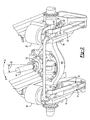
- a suspension system 10 is shown in Figures 1 and 2.
- the system 10 includes a frame that may include longitudinal rails, brackets, and other structural members secured by welds, fasteners or other attachment means.
- the suspension system 10 includes a pair of spaced apart trailing arms 14.
- the trailing arms 14 are preferably formed of a rather thick metal forming having opposing sides and an upper side 15 adjoining the opposing sides to form an inverted U-shape.
- the lower side 16 is open forming a channel, as best shown in Figure 2.
- the trailing arms 14 include a forward portion 17 pivotally attached to the frame and extending longitudinally rearward to a rearward portion 18.
- Air springs 20 and shock absorbers 22 may be arranged between the trailing arms 14 and the frame 12.
- An anti-roll bar 24 may be removably secured between the trailing arms 14 to provide stability to the vehicle during turning maneuvers.
- the suspension system 10 extends along a longitudinal axis L.
- An axle 26 includes opposing end portions 29 that are pivotally secured to the trailing arms 14 via brackets 30.
- the trailing arms 14 may include a sleeve 32 welded between the opposing sides of the trailing arm 14.
- a pin 34 may be disposed within the sleeve 32 and laterally located using a flexible material 33 which provides some compliance during movement of the suspension.
- the pins 34 include opposing ends 36 with apertures (not shown).
- a conventional bushing arrangement may be used such as the one depicted on the forward portion 17.
- the brackets 30 include an upper end attached to the end portions 29 of the axle 26 by welding or other attaching means.
- the brackets 30 includes lower ends 38 having spaced apart legs 40. Each of the legs 40 are secured to the opposing ends 36 by fastening members 42. The bracket 30 straddles the trailing arm 40 such that the legs 40 are on either side of the trailing arm 14.
- a V-rod 44 is attached between the frame 12 and the axle 26 to provide stability to the axle 26 during movement of the suspension.
- the V-rod 44 includes first 46 and second 48 ends extending to a common third end 50.
- the first 46 and second 48 ends are pivotally secured to the frame by a pin 51 rotatably received in the ends and secured to the frame 12 by fastening members.
- the third end 50 is secured to the axle 26 by pin 51 rotatably received in the end and secured to the axle 26 by fastening elements.
- the axle includes an input shaft 52 receiving rotational drive from a driveshaft 54 from an engine, typically located rearward of the suspension system 10 for motor home applications.
- Pinion angle is defined by the configuration of the trailing arm 14 and the V-rod 44.
- the present invention suspension system configuration is that of a parallelogram, preferably so that the pinion angle 56 remains constant as the suspension system moves between first A and second B positions.
- the pivotal attachment from the trailing arm 14 to the frame 12 to the pivotal attachment of the trailing arm 14 to the axle 26 defines a first length.
- the longitudinal distance from the first and second ends 46 and 48 to the third end 50 defines a second length.
- the first and second lengths are equal.
- the vertical distance from the first and second ends 46 and 48 and the pivotal connection from the trailing arm 14 to the frame 12 defines a third length.
- the vertical distance from the third end 50 and the pivotal connection between the axle 26 and the trailing arm 14 defines a fourth length.
- the third and fourth lengths are equal. In this manner, a parallelogram suspension configuration is provided in which the pinion angle 56 is maintained during movement of the suspension between first A and second B positions.
Landscapes
- Engineering & Computer Science (AREA)
- Mechanical Engineering (AREA)
- Vehicle Body Suspensions (AREA)
Applications Claiming Priority (2)
| Application Number | Priority Date | Filing Date | Title |
|---|---|---|---|
| US194817 | 2002-07-12 | ||
| US10/194,817 US6886840B2 (en) | 2002-07-12 | 2002-07-12 | Heavy duty trailing arm suspension system |
Publications (2)
| Publication Number | Publication Date |
|---|---|
| EP1380450A2 true EP1380450A2 (fr) | 2004-01-14 |
| EP1380450A3 EP1380450A3 (fr) | 2005-04-27 |
Family
ID=29735355
Family Applications (1)
| Application Number | Title | Priority Date | Filing Date |
|---|---|---|---|
| EP03254315A Withdrawn EP1380450A3 (fr) | 2002-07-12 | 2003-07-08 | Bras de suspension |
Country Status (2)
| Country | Link |
|---|---|
| US (1) | US6886840B2 (fr) |
| EP (1) | EP1380450A3 (fr) |
Cited By (1)
| Publication number | Priority date | Publication date | Assignee | Title |
|---|---|---|---|---|
| US11491838B2 (en) * | 2018-07-10 | 2022-11-08 | Iveco S.P.A. | Suspension for a vehicle |
Families Citing this family (16)
| Publication number | Priority date | Publication date | Assignee | Title |
|---|---|---|---|---|
| US7967307B2 (en) * | 2002-07-12 | 2011-06-28 | Arvinmeritor Technology, Llc | Heavy duty trailing arm suspension system |
| US7178817B1 (en) * | 2002-11-01 | 2007-02-20 | Monaco Coach Corporation | Trailing arm suspension system |
| ES2258374B1 (es) * | 2004-01-21 | 2007-11-16 | Automoviles Utilitarios, S.A. | Sistema de suspension para vehiculos. |
| US7540513B2 (en) * | 2005-10-25 | 2009-06-02 | Arvinmeritor Technology, Llc | Anti-roll bar and control arm assembly |
| US7798503B2 (en) * | 2006-01-16 | 2010-09-21 | The Pullman Company | Cast apex adjustable V-type torque rod |
| JP4127298B2 (ja) * | 2006-06-14 | 2008-07-30 | トヨタ自動車株式会社 | 車輪車体間距離調整装置および車輪車体間距離調整システム |
| US7618049B2 (en) | 2006-09-15 | 2009-11-17 | Arvinmeritor Technology, Llc | Trailing arm suspension |
| US7789405B2 (en) * | 2008-07-14 | 2010-09-07 | Link Manufacturing, Ltd. | Linkage-type air suspension system |
| US8371596B2 (en) * | 2009-05-13 | 2013-02-12 | Saf-Holland, Inc. | Suspension system for heavy and vocational vehicles |
| US8465036B2 (en) | 2011-08-02 | 2013-06-18 | Arvinmeritor Technology, Llc | Side mounted air spring trailing arm suspension |
| US8955860B2 (en) | 2012-03-28 | 2015-02-17 | Saf-Holland, Inc. | Vehicle suspension assembly with integrated torque member and trailing arm mount |
| US9004511B1 (en) * | 2013-10-09 | 2015-04-14 | Honda Motor Co., Ltd. | Stabilizing bar mounting structure |
| US9180735B2 (en) | 2013-12-02 | 2015-11-10 | Hendrickson Usa, L.L.C. | V-rod attachment assembly for vehicle suspension |
| US10967927B2 (en) | 2017-09-22 | 2021-04-06 | Link Mfg., Ltd. | Mounting brackets for auxiliary suspension systems |
| RU2769203C1 (ru) * | 2021-06-28 | 2022-03-29 | Федеральное государственное бюджетное образовательное учреждение высшего образования "Санкт-Петербургский государственный архитектурно-строительный университет" | Задняя подвеска транспортного средства |
| CA3226220A1 (fr) | 2021-07-08 | 2023-01-12 | Link Mfg., Ltd. | Essieux relevables entraines ainsi que systemes et procedes associes |
Family Cites Families (13)
| Publication number | Priority date | Publication date | Assignee | Title |
|---|---|---|---|---|
| US3406983A (en) * | 1966-11-25 | 1968-10-22 | Neway Equipment Co | Suspension for automotive vehicles |
| US4415179A (en) * | 1981-04-15 | 1983-11-15 | Marinelli Joseph A | Axle and air bag suspension |
| US4717171A (en) * | 1985-07-03 | 1988-01-05 | Honda Giken Kogyo Kabushiki Kaisha | Wheel suspension for road vehicles |
| US5524921A (en) * | 1995-04-26 | 1996-06-11 | Paccar Inc. | V-bar suspension linkage |
| DE19521875C2 (de) * | 1995-06-16 | 2002-04-18 | Zf Lemfoerder Metallwaren Ag | Achsaufhängung für Starrachsen in Fahrzeugen |
| SE514129C2 (sv) * | 1998-01-16 | 2001-01-08 | Scania Cv Ab | Krängningshämmare |
| MXPA00012632A (es) * | 1998-07-02 | 2002-07-02 | Boler Co | Sistema de eje/suspension de brazo de remolque. |
| ES2207938T3 (es) * | 1999-03-02 | 2004-06-01 | Zf Lemforder Metallwaren Ag | Suspension de eje de ejes rigidos. |
| US6267526B1 (en) * | 1999-06-28 | 2001-07-31 | The Pullman Company | Headed solid rod for torque rod spacer |
| US6375203B1 (en) * | 1999-08-09 | 2002-04-23 | International Truck And Engine Corp. | Front air spring suspension with leading arm trailing and V-link |
| DE60012370T2 (de) | 1999-11-24 | 2005-09-08 | Holland USA, Inc., Muskegon | Längsarmaufhängung |
| US6533299B2 (en) * | 2000-11-29 | 2003-03-18 | Meritor Heavy Vehicle Technology, Llc | Drive axle air suspension |
| US6557875B2 (en) * | 2001-03-21 | 2003-05-06 | Dana Corporation | Vehicle suspension |
-
2002
- 2002-07-12 US US10/194,817 patent/US6886840B2/en not_active Expired - Lifetime
-
2003
- 2003-07-08 EP EP03254315A patent/EP1380450A3/fr not_active Withdrawn
Non-Patent Citations (1)
| Title |
|---|
| None |
Cited By (1)
| Publication number | Priority date | Publication date | Assignee | Title |
|---|---|---|---|---|
| US11491838B2 (en) * | 2018-07-10 | 2022-11-08 | Iveco S.P.A. | Suspension for a vehicle |
Also Published As
| Publication number | Publication date |
|---|---|
| EP1380450A3 (fr) | 2005-04-27 |
| US20040007845A1 (en) | 2004-01-15 |
| US6886840B2 (en) | 2005-05-03 |
Similar Documents
| Publication | Publication Date | Title |
|---|---|---|
| US6886840B2 (en) | Heavy duty trailing arm suspension system | |
| US7967307B2 (en) | Heavy duty trailing arm suspension system | |
| US6733021B1 (en) | Vehicle subframe mounting | |
| US4641854A (en) | Wheel suspension for a vehicle | |
| EP0880440B1 (fr) | Suspension a tringlerie | |
| US5639110A (en) | Trailing arm suspension | |
| US8172244B2 (en) | Rear axle for a motor vehicle | |
| CN102858562B (zh) | 重型轴梁连接件 | |
| US6733020B2 (en) | Suspension trailing arm | |
| CN102666154A (zh) | 扭转式车轴的扭力梁 | |
| CN203186026U (zh) | 一种新型mpv后独立悬架系统 | |
| US20070013160A1 (en) | Steer axle suspension | |
| CN100455453C (zh) | 悬架和轴组件 | |
| EP1380449A2 (fr) | Suspension à bras oscillant | |
| MXPA04011510A (es) | Suspension con eje de direccion. | |
| US20100044988A1 (en) | Integrated Swaybar and Torque Rod Suspension Link | |
| US11926363B2 (en) | Work vehicle | |
| AU2018318011B2 (en) | Axle/suspension system with down stop | |
| JP2005041402A (ja) | ブラケット構造 | |
| EP1348580A1 (fr) | Suspension indépendante pour une roue d'un véhicule utilitaire | |
| JP3947123B2 (ja) | キャブサスペンション装置 | |
| DE10250344B4 (de) | Schräglenker-Hinterradachse für leichte Nutzkraftfahrzeuge | |
| JPH06262920A (ja) | リンク取付け構造 | |
| JP4258446B2 (ja) | 車輪支持構造 | |
| AU706633B2 (en) | Trailing arm |
Legal Events
| Date | Code | Title | Description |
|---|---|---|---|
| PUAI | Public reference made under article 153(3) epc to a published international application that has entered the european phase |
Free format text: ORIGINAL CODE: 0009012 |
|
| AK | Designated contracting states |
Kind code of ref document: A2 Designated state(s): AT BE BG CH CY CZ DE DK EE ES FI FR GB GR HU IE IT LI LU MC NL PT RO SE SI SK TR |
|
| AX | Request for extension of the european patent |
Extension state: AL LT LV MK |
|
| PUAL | Search report despatched |
Free format text: ORIGINAL CODE: 0009013 |
|
| AK | Designated contracting states |
Kind code of ref document: A3 Designated state(s): AT BE BG CH CY CZ DE DK EE ES FI FR GB GR HU IE IT LI LU MC NL PT RO SE SI SK TR |
|
| AX | Request for extension of the european patent |
Extension state: AL LT LV MK |
|
| RIC1 | Information provided on ipc code assigned before grant |
Ipc: 7B 60G 11/27 B Ipc: 7B 60G 9/02 B Ipc: 7B 60G 7/00 B Ipc: 7B 60G 9/00 A |
|
| 17P | Request for examination filed |
Effective date: 20051010 |
|
| AKX | Designation fees paid |
Designated state(s): DE FR GB IT SE |
|
| 17Q | First examination report despatched |
Effective date: 20071114 |
|
| STAA | Information on the status of an ep patent application or granted ep patent |
Free format text: STATUS: THE APPLICATION IS DEEMED TO BE WITHDRAWN |
|
| 18D | Application deemed to be withdrawn |
Effective date: 20080326 |