EP1380462B1 - Dispositif d'attache pour un conteneur - Google Patents
Dispositif d'attache pour un conteneur Download PDFInfo
- Publication number
- EP1380462B1 EP1380462B1 EP20030015158 EP03015158A EP1380462B1 EP 1380462 B1 EP1380462 B1 EP 1380462B1 EP 20030015158 EP20030015158 EP 20030015158 EP 03015158 A EP03015158 A EP 03015158A EP 1380462 B1 EP1380462 B1 EP 1380462B1
- Authority
- EP
- European Patent Office
- Prior art keywords
- container
- tensioning
- container holder
- fastening apparatus
- longitudinal axis
- Prior art date
- Legal status (The legal status is an assumption and is not a legal conclusion. Google has not performed a legal analysis and makes no representation as to the accuracy of the status listed.)
- Expired - Lifetime
Links
- 239000002828 fuel tank Substances 0.000 claims description 13
- 230000003014 reinforcing effect Effects 0.000 claims description 13
- 230000035515 penetration Effects 0.000 claims 1
- 239000007789 gas Substances 0.000 description 31
- 230000001133 acceleration Effects 0.000 description 7
- 238000004519 manufacturing process Methods 0.000 description 5
- VNWKTOKETHGBQD-UHFFFAOYSA-N methane Chemical compound C VNWKTOKETHGBQD-UHFFFAOYSA-N 0.000 description 4
- XEEYBQQBJWHFJM-UHFFFAOYSA-N Iron Chemical compound [Fe] XEEYBQQBJWHFJM-UHFFFAOYSA-N 0.000 description 2
- 238000011161 development Methods 0.000 description 2
- 230000018109 developmental process Effects 0.000 description 2
- 238000000034 method Methods 0.000 description 2
- 239000003345 natural gas Substances 0.000 description 2
- 238000010008 shearing Methods 0.000 description 2
- 238000004458 analytical method Methods 0.000 description 1
- 230000000295 complement effect Effects 0.000 description 1
- 230000007547 defect Effects 0.000 description 1
- 230000001419 dependent effect Effects 0.000 description 1
- 230000005489 elastic deformation Effects 0.000 description 1
- 238000009434 installation Methods 0.000 description 1
- 229910052742 iron Inorganic materials 0.000 description 1
- 239000000463 material Substances 0.000 description 1
- 230000010355 oscillation Effects 0.000 description 1
- 230000008092 positive effect Effects 0.000 description 1
- 230000001681 protective effect Effects 0.000 description 1
- 238000005096 rolling process Methods 0.000 description 1
- 238000007789 sealing Methods 0.000 description 1
- 238000003466 welding Methods 0.000 description 1
Images


Classifications
-
- B—PERFORMING OPERATIONS; TRANSPORTING
- B60—VEHICLES IN GENERAL
- B60K—ARRANGEMENT OR MOUNTING OF PROPULSION UNITS OR OF TRANSMISSIONS IN VEHICLES; ARRANGEMENT OR MOUNTING OF PLURAL DIVERSE PRIME-MOVERS IN VEHICLES; AUXILIARY DRIVES FOR VEHICLES; INSTRUMENTATION OR DASHBOARDS FOR VEHICLES; ARRANGEMENTS IN CONNECTION WITH COOLING, AIR INTAKE, GAS EXHAUST OR FUEL SUPPLY OF PROPULSION UNITS IN VEHICLES
- B60K15/00—Arrangement in connection with fuel supply of combustion engines or other fuel consuming energy converters, e.g. fuel cells; Mounting or construction of fuel tanks
- B60K15/03—Fuel tanks
- B60K15/063—Arrangement of tanks
- B60K15/067—Mounting of tanks
-
- B—PERFORMING OPERATIONS; TRANSPORTING
- B60—VEHICLES IN GENERAL
- B60K—ARRANGEMENT OR MOUNTING OF PROPULSION UNITS OR OF TRANSMISSIONS IN VEHICLES; ARRANGEMENT OR MOUNTING OF PLURAL DIVERSE PRIME-MOVERS IN VEHICLES; AUXILIARY DRIVES FOR VEHICLES; INSTRUMENTATION OR DASHBOARDS FOR VEHICLES; ARRANGEMENTS IN CONNECTION WITH COOLING, AIR INTAKE, GAS EXHAUST OR FUEL SUPPLY OF PROPULSION UNITS IN VEHICLES
- B60K15/00—Arrangement in connection with fuel supply of combustion engines or other fuel consuming energy converters, e.g. fuel cells; Mounting or construction of fuel tanks
- B60K15/03—Fuel tanks
- B60K15/063—Arrangement of tanks
- B60K15/067—Mounting of tanks
- B60K15/07—Mounting of tanks of gas tanks
Definitions
- the present invention relates to a fastening device for containers, such as high-pressure vessels, fuel tanks, gas cylinders or the like, to the substructure of the body of a motor vehicle, according to the preamble of claim 1.
- the DE 199 12 671 C1 Such a device for releasably supporting tubular bodies on or at the loading areas of Motor vehicles. With this device, tubular bodies are to be held quickly and without tools safely and immovably on or at the loading areas of motor vehicles and can be released again as quickly as required.
- the DE 199 36 653 A1 by the same applicant discloses a further variant of a device for releasably holding tubular bodies, such as gas cylinders, tubes, tubular containers or the like. This variant is intended as a further development to the aforementioned variant have a Umtschich réelle and an anti-rotation.
- detachable gas bottle holder is known from DE 93 01 537.2 U1 known.
- a device for fixing a plurality of cylindrical containers, such as gas cylinders, in a caddy with a base plate and connected thereto lateral struts, which are distributed along the base plate, wherein the device comprises strips, in particular of flat iron, on the uppermost layer of the containers are arranged across the width of the stack between two struts and occupy the shape of the containers of the uppermost layer, the apparatus having clamping means for clamping the entire bottle package consisting of a plurality of gas cylinders.
- This device is used to transport a variety the same gas bottles, for example, on a trailer or a truck.
- the fuel tank such as a gas cylinder
- the tension bands comprise the circumference of the body facing away from the base of the body
- a commercially available turnbuckle has been provided in practice, one side of which is connected to one end of the tension band and the other side is screwed by means of the fastening screws on the L-shaped container holder.
- a fastening device according to the preamble of claim 1 is known, in which a container by means of two clamping straps in two container holders, where the straps are attached, is supported.
- the two container holder are formed in a half-shell shape and have a complementary to the outer contour of the container support surface in which the container rests positively.
- the DE 200 11 592 U1 Similar solutions are known, the DE 200 11 592 U1 the well-known art, as in the WO 98/02324 is shown, expressly criticized.
- Object of the present invention is therefore such known from practice fastening devices for containers, such as high-pressure tank, fuel tanks, gas cylinders, or the like, further develop such that a fuel tank while avoiding the aforementioned disadvantages safely against twisting, slipping or even tearing permanently on the base of Body of a motor vehicle can be attached.
- a fastening device for containers such as high-pressure vessels, fuel tanks, gas cylinders, or the like, proposed, which are to be fixed to the base of the body of a motor vehicle by means of this fastening device, said fastening device has at least two at least partially comprehensive clamping bands and two Container holders to which the straps are attached.
- the longitudinal axis of the container is preferably oriented transversely to the vehicle longitudinal axis, wherein the container holders extend on either side of the container parallel to its longitudinal axis, and wherein the container is disposed between the container holders.
- At least one of the two container holders is V-shaped in cross-section with a technological tip so that at least one attachment point of the container-facing leg of the V-shaped container holder lies on the underside within the container contour projected perpendicular to the base, wherein the strap and container holder largely conform to the container cross-section and thereby include the container cross-section as much as possible.
- V-shaped design of the container holder cross-section that the container as far as possible against the left and right of the container him facing shoulders or legs of the respective adjacent V-shaped container holder can be supported, so that the base to be fixed container in principle, as in a contoured on his tray or shell rests, from which this can not move out even in sudden acceleration or deceleration, as may occur, for example, in a head-on collision or a rear impact.
- the V-shaped container holder is advantageously torsionally rigid and thus more stable than conventional, for example L-shaped, container holder with the same wall thicknesses.
- the V-shaped container holder takes, for example, even those forces that can occur in a sharp acceleration or deceleration of the vehicle due to the inertia of the container in the horizontal direction, easily complete.
- Such forces are absorbed by the respective facing legs of the V-shaped container holder and of these on the one hand - depending on whether a pushing or pulling force acting on the leg facing the container - passed accordingly as Switzerlandoder thrust in the substructure and on the other hand as thrust - or tensile force on the outer leg derived in the substructure.
- the straps fastened to the two container holders ensure in an advantageous manner that the containers enclosed between the V-shaped container holders do not roll over the respectively affected flank over the V-shaped container holder and thus out of the container can move out of the two container holders and the substructure formed pan or shell.
- the fastening device according to the invention provides for the first time advantageously an economically manufacturable, cost-effective solution of the above-known from practice problems, which is also feasible in a mass production beyond.
- the two V-shaped container holder can be screwed in a conventional manner for mounting against the subfloor, welded, dotted or crimped.
- the attachment of the container holder to the subfloor is merely to be interpreted so that the maximum forces can be intercepted and introduced into the subfloor.
- the tensioning band is fastened to the container holder by means of a turnbuckle such that the tensile forces prevailing in the tensioning band can in turn be introduced into the container holder via a tensioning screw as tensile forces and as far as possible without shearing forces.
- a turnbuckle provides the ability to impart exactly the predetermined clamping force on the strap so that the fixed with a fastening device according to the invention attached to the base container is optimally secured and permanently secured against unwanted twisting, commuting, or move out of its position ,
- a commercially available turnbuckle can advantageously be used at correspondingly low prices, which in turn has a positive effect on the production costs of the fastening device according to the invention.
- a further preferred embodiment proposes that the tension lock interposed between the container holder and the clamping band end has two, preferably cylindrical, clamping bodies with a threaded bore oriented perpendicular to the extension direction of the clamping body, in which the clamping screw engages, wherein the first clamping body is located in the tip of the clamping body.
- shaped container holder is rotatably disposed about its longitudinal axis and the second clamping body is rotatably encompassed by a tab on the clamping band end about its longitudinal axis, wherein the tab and the container holder each having a recess through which the clamping screw are screwed through the second clamping body into the first clamping body can.
- connection of the clamping band end by means of the turnbuckle with the mounting bracket ensures by the mutually rotatable articulation of the turnbuckle ends on Spannbandende or on the mounting bracket that no unwanted moments in the power flow from the strap can occur to the container holder. This is a completely kink-free connection can be realized.
- the clamping bodies of the turnbuckles can be hooked into the V-shaped container holder with the least possible installation effort, so that this preferred embodiment is not only accessible to mass production due to the ease of assembly, but also represents a particularly cost-effective alternative.
- the clamping bolt can be easily hooked into the strap-like strap end. The same applies to the extremely simple handling when connecting the two clamping body with the clamping screw.
- the tension band is fastened to the container holder by means of a tensioning bracket in such a way that the tension forces prevailing on the tension band can in turn be introduced into the container holder via a tension bolt as tensile forces and as far as possible without shear forces.
- the interposed between the container holder and the clamping band end clamping bracket is designed as a double-T-bolt or H-bolt, the two preferably at least semi-cylindrical.
- Clamping body with a vertical to the extension direction of the clamping body oriented connecting bolt wherein the first clamping body by means of a recess in the tip of the V-shaped container holder is rotatably suspended about its longitudinal axis and the second clamping body is rotatably encompassed by a tab on the clamping band end about its longitudinal axis, wherein the tab is a recess has, through which the second clamping body of the clamping bracket is suspended through.
- the fastening device has in a further preferred embodiment, two V-shaped container holder with recesses for the passage of clamping screws or clamping bolts for associated clamping body of turnbuckles or clamps, and has either two turnbuckles or a turnbuckle and a clamping bracket per strap.
- the leg of the V-shaped container holder facing away from the container is supported against the vehicle longitudinal axis parallel to the vehicle longitudinal axis and thus preferably oriented perpendicular to the direction of orientation of the container holder Reinforcing ribs that form so-called "crash boxes" as a crumple zone in a rear impact.
- the reinforcing ribs on both sides of the container can be assigned to each container holder. It is also conceivable to provide only on one side of such reinforcing ribs.
- the dimensioning of these components can be further optimized in this way, so that they can be designed to save weight and material as light and slim as possible.
- the support of the container holder can be screwed against the reinforcing ribs, for example, for a permanent fixation, welded, dotted, crimped or otherwise executed. The same applies to the attachment of the reinforcing ribs on the substructure.
- the clamping body is designed as a cylindrical sleeve. This is one of the cheapest and easiest to manufacture variants.
- the angle ⁇ facing the container between the substructure and the container-facing leg of the V-shaped container holder is between 110 ° and 130 °, in particular 120 °.
- the angle ⁇ facing the container between the substructure and the container-facing leg of the V-shaped container holder is between 110 ° and 130 °, in particular 120 °.
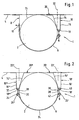
- FIG. 1 is a simplified schematic section of a first exemplary embodiment of a fastening device 1 according to the invention for container 2, such as high-pressure vessels, fuel tanks, or here a gas cylinder, or the like, for their attachment to the base 4 of the body not shown in detail of a motor vehicle not shown.
- container 2 such as high-pressure vessels, fuel tanks, or here a gas cylinder, or the like
- the container 2 is at least partially enclosed by a tension band 6 and arranged between two container holders 8 and 10.
- the left container holder 8 is formed in the variant shown here as an L-shaped container holder.
- the clamping band 6 with at least one fastening means 12, which may be formed, for example, as a fastening screw mounted.
- the right in this representation container holder 10 has a V-shaped cross-section. Whose two legs 14 and 16 are fastened to the base 4 with fastening means, not shown, such as screws or a welded joint, spot welding or Krimpthetic.
- the tip 18 of the V-shaped container holder 10 faces away from the base 4.
- the attachment point 20 of the container 2 facing leg 14 of the V-shaped right container holder 10 with the bottom 4 is within the container contour projected perpendicular to the base 4, as the dashed line 22 is intended to illustrate.
- both clamping band 6 and container holder 10 nestle as far as possible on the container cross-section 24 of the container 2, wherein they include the container cross-section 24 as far as possible.
- FIG. 2 is a further exemplary embodiment of a fastening device 1 according to the invention for container 2 shown for their attachment to the base 4 of the body of a motor vehicle not shown in a simplified schematic representation.
- the container 2 is held by two V-shaped container holders 10 'and 10 ".
- the clamping band 6 is in this illustration with its left end, which is formed into a tab 26", by means of a tensioning bracket 28 with the tip 18'. 'of the left container holder 10 "connected.
- the clamping bracket 28 has a clamping bolt 30.
- the Spannhbügel 28 may be formed as a double-T-bolt or H-bolt, which has two, preferably at least semi-cylindrical, clamping body 32 and 34, respectively in the top 18 "of the V-shaped container holder 10" and in contrast are hung in the tab 26 "of the tension band 6.
- the right clamping band end is also formed in the form of a tab 26 '.
- the right clamping band end is connected by means of a turnbuckle 36 to the tip 18 'of the right container holder 10'.
- the turnbuckle 36 has a tightening screw 38 by means of which the tension forces prevailing in the tightening strap 6 can in turn be introduced as tensile forces and as far as possible without shear forces into the receptacle holder 10 '.
- the turnbuckle 36 also has two, preferably cylindrical, clamping bodies 40 and 42 with a substantially perpendicular to the direction of extension of the clamping body oriented - not shown here - threaded hole into which the clamping screw 38 engages.
- the first clamping body 40 is rotatably supported in the tip 18 'of the V-shaped container holder 10' about its longitudinal axis.
- the second clamping body 42 is rotatably encompassed by the tab 26 'at the right clamping band end about its longitudinal axis.
- attachment points 20 'and 20 "of each of the left and right in the representation shown here the container 2 facing legs 14" and 14' are located on the bottom 4 within the projected perpendicular to the base 4 container contour, which in turn here with the dashed lines 22nd should be indicated 'or 22'.
- FIG. 3 reproduced three-dimensional view of a schematically simplified illustration of an exemplary embodiment illustrates the fixation of the container 2 on the partially illustrated substructure 4.
- the V-shaped container holder 10 '' is shown in the left part of the picture.
- This has recesses 44 in which the clamping body 32 of the here designed as a double T-bolt or H-bolt tension bracket 28 are mounted.
- the left clamping band ends of the tensioning straps 6 are designed as straps 26 ", which have straps 26" Recesses 46 for the passage of the tension bracket 28.
- a fitting 48 of the container 2 is shown on the right edge of the picture. Further, a reinforcing rib 50 is fixed to the base 4 for additional support of the right container holder 10 '.
- FIG. 4 is again in a schematic simplified three-dimensional view obliquely from below the only partially illustrated substructure with the already in Fig. 3 shown exemplary embodiment of the fastening device 1 according to the invention fixed container 2 shown.
- the view reproduced here focuses on the right side of the container. 2
- FIG. 4 In the left picture section of Fig. 4 is the fitting 48 recognizable with the associated modules.
- the container 2 is braced against the container holders 10 'and 10 "by means of two tension bands 6.
- the right end of the tension bands 6 is in each case designed as a tab 26.
- the tab 26' has recesses 52 through which the tensioning screw 38 of the turnbuckle 36 passes.
- the clamping body 42 through which the clamping screw 38 passes, is suspended in the lug 26 '
- the clamping body 42 is shown in the embodiment variant shown here as a cylindrical sleeve with a threaded bore 54 oriented substantially perpendicular to the extension direction of the clamping body 42 38 engages through a recess 56, which is arranged in the top of the V-shaped container holder 10 'through it into the clamping body 40 therein.
- the container holder 10 ' is additionally supported with its side facing away from the container 2 leg 16' against reinforcing ribs 50, which in turn are attached to the bottom 4.
- the reinforcing ribs 50 are preformed so that they can absorb as much kinetic energy as possible in an impact.
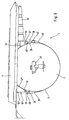
- Fig. 5 is the in Figures 3 and 4 illustrated embodiment again shown schematically simplified in a side view. From this representation, it is very clear that the container 2 in a kind of pan or shell, which is formed by the bottom 4 and the two container holders 10 'and 10 "and the container facing legs 14' and 14" to the Contour or contiguous to the container cross-section of the container 2, rests, the contour of the container 2 from the clamping band 6, the left of the container 2 by means of the clamping bracket 28 with the container holder 10 "is braced and which right of the container 2 with the turnbuckle 36th is attached to the container holder 10 'is included as far as possible.
- the tension band 6, the tension bow 28, the container holder 10 "of the affected portion of the subfloor 4, the container holder 10 'and the turnbuckle 36 a container 2 fully wrapped around the clamping ring, which conforms so well to the contour or the container cross-section
- FIGS. 1 to 5 are the same or equivalent parts or components provided with the same reference numerals, for ease of illustration.
- the present invention thus provides for the first time a fastening device for containers, such as fuel tanks, gas cylinders, or the like, which are to be mounted by means of the fastening device to the base of the body of a motor vehicle.
- this fastening device at least two clamping bands at least partially comprising the container, and two container holder to which the clamping bands are attached.
- the longitudinal axis of the container is preferably oriented transversely to the vehicle longitudinal axis, wherein the container holders extend on either side of the container parallel to the longitudinal axis of the container, and wherein the container is disposed between the container holders. It is provided for the first time that at least one of the two container holder is formed in cross-section V-shaped with the technological V-tip from the base.
- At least one attachment point of the container-facing leg of the V-shaped container holder is disposed on the underside within the container contour projected perpendicular to the substructure, wherein the clamping band and container holder largely conform to the container cross section and thereby include the container cross section as much as possible.
Landscapes
- Engineering & Computer Science (AREA)
- Life Sciences & Earth Sciences (AREA)
- Sustainable Development (AREA)
- Sustainable Energy (AREA)
- Chemical & Material Sciences (AREA)
- Combustion & Propulsion (AREA)
- Transportation (AREA)
- Mechanical Engineering (AREA)
- Cooling, Air Intake And Gas Exhaust, And Fuel Tank Arrangements In Propulsion Units (AREA)
- Filling Or Discharging Of Gas Storage Vessels (AREA)
- Clamps And Clips (AREA)
Claims (12)
- Dispositif de fixation (1) pour fixer des réservoirs (2) tels que des réservoirs sous haute pression, réservoirs de carburant, bouteilles de gaz ou similaires sur le bas de caisse (4) de la carrosserie d'un véhicule à moteur, avec au moins deux sangles de serrage (6) entourant au moins partiellement le réservoir (2) et avec deux supports de réservoir (8) auxquels les sangles de serrage sont fixées, dans lequel le réservoir (2) est disposé entre les supports de réservoir (8) et dans lequel la sangle de serrage (6, 6', 6") s'applique le plus étroitement possible sur la section (24) du réservoir et entoure ainsi la section (24) du réservoir autant que possible, caractérisé en ce que les supports de réservoir (8) s'étendent de part et d'autre du réservoir (2) parallèlement à l'axe longitudinal du réservoir (2) et au moins un des deux supports de réservoir (10, 10', 10") est en forme de V en section avec une pointe (18, 18', 18") dirigée à l'opposé du bas de caisse (4), de sorte qu'au moins un point de fixation (20, 20', 20") du bras (14, 14', 14") du support de réservoir en forme de V (10) dirigé vers le réservoir (2) se trouve à l'intérieur du contour de réservoir (22, 22', 22") projeté vers le bas de caisse (4).
- Dispositif de fixation (1) selon la revendication 1, caractérisé en ce que la sangle de serrage (6) est fixé au moyen d'un tendeur (36) sur le support de réservoir (10, 10') de telle façon que les forces de traction régnant dans la sangle de serrage (6) puissent être transmises par l'intermédiaire d'une vis de serrage (38) au support de réservoir (10, 10') sous la forme de forces de traction.
- Dispositif de fixation (1) selon la revendication 2, caractérisé en ce que le tendeur (36) intercalé entre le support de réservoir (10, 10') et l'extrémité (26') de la sangle de serrage présente deux éléments de serrage (40, 42) avec un trou fileté (54) orienté perpendiculairement au sens d'extension de l'élément de serrage (40, 42) dans lequel la vis de serrage (38) se met en prise, le premier élément de serrage (40) étant disposé dans la pointe (18, 18') du support de réservoir en forme de V (10, 10') avec possibilité de rotation autour de son axe longitudinal et le deuxième élément de serrage (42) étant entouré par une patte (26') à l'extrémité de la sangle de serrage avec possibilité de rotation autour de son axe longitudinal, la patte (26') et le support de réservoir (10') présentant chacun une ouverture (52) à travers laquelle la vis de serrage (38) peut être vissée à travers le deuxième élément de serrage (42) dans le premier élément de serrage (40).
- Dispositif de fixation (1) selon l'une des revendications 1 à 3, caractérisé en ce que la sangle de serrage (6) est fixée au moyen d'une étrier de tension (28) au support de réservoir (10") de telle façon que les forces de traction régnant dans la sangle de serrage (6) puissent être transmises par l'intermédiaire d'un boulon de tension (30) au support de réservoir (10") sous la forme de forces de traction.
- Dispositif de fixation (1) selon la revendication 4, caractérisé en ce que l'étrier de tension (28) intercalé entre le support de réservoir (10") et l'extrémité (26") de la sangle de traction est conformé comme un boulon en double T ou un boulon en H, qui présente deux éléments de serrage (32, 34), de préférence au moins demi-cylindriques, avec un boulon de liaison (30) orienté perpendiculairement à la direction d'extension des éléments de serrage (32, 34), le premier élément de serrage (32) pouvant être accroché au moyen d'une ouverture (44) dans la pointe (18") du support de réservoir en forme de V (10") avec possibilité de rotation autour de son axe longitudinal et le deuxième élément de serrage (34) étant entouré par une patte (26") à l'extrémité de la sangle de serrage avec possibilité de rotation autour de son axe longitudinal, la patte (26") présentant une ouverture (46) à travers laquelle le deuxième élément de serrage (34) de l'étrier de tension peut être accroché.
- Dispositif de fixation (1) selon l'une des revendications 1 à 5, caractérisé en ce que les deux supports de réservoir (10, 10', 10") sont en forme de V en section et sont munis d'ouvertures pour le passage de vis de serrage (38) ou de boulons de tension (30) pour des éléments de serrage (32, 34, 40, 42) associés de tendeurs (36) ou d'étriers de tension (28) et le dispositif de fixation (1) présente soit deux tendeurs (36), soit un tendeur (36) et un étrier de tension (28) par sangle de serrage (6).
- Dispositif de fixation (1) selon l'une des revendications 1 à 6, caractérisé en ce que le bras (16, 16', 16") du support de réservoir en forme de V (10, 10' 10") opposé au réservoir (2) s'appuie contre des nervures de renfort (50) orientées parallèlement à l'axe longitudinal du véhicule.
- Dispositif de fixation (1) selon l'une des revendications 1 à 7, caractérisé en ce que l'élément de serrage (32, 34, 40, 42) est conformé comme une douille cylindrique (54).
- Dispositif de fixation (1) selon l'une des revendications 1 à 8, caractérisé en ce que l'angle α dirigé vers le réservoir (2) entre le bas de caisse (4) et le bras (14, 14', 14") dirigé vers le réservoir du support de réservoir en forme de V (10, 10', 10") est compris entre 110° et 130°.
- Dispositif de fixation (1) selon la revendication 9, caractérisé en ce que l'angle α dirigé vers le réservoir (2) entre le bas de caisse (4) et le bras (14, 14', 14") dirigé vers le réservoir du support de réservoir en forme de V (10, 10', 10") est de 120°.
- Dispositif de fixation (1) selon l'une des revendications précédentes, caractérisé en ce que l'axe longitudinal du réservoir (2) est orienté perpendiculairement à l'axe longitudinal du véhicule.
- Dispositif de fixation (1) selon l'une des revendications précédentes, caractérisé en ce que les deux élément de serrage (40, 42) sont de forme cylindrique.
Applications Claiming Priority (2)
| Application Number | Priority Date | Filing Date | Title |
|---|---|---|---|
| DE10230635 | 2002-07-08 | ||
| DE2002130635 DE10230635A1 (de) | 2002-07-08 | 2002-07-08 | Befestigungsvorrichtung für Behälter |
Publications (3)
| Publication Number | Publication Date |
|---|---|
| EP1380462A2 EP1380462A2 (fr) | 2004-01-14 |
| EP1380462A3 EP1380462A3 (fr) | 2006-12-20 |
| EP1380462B1 true EP1380462B1 (fr) | 2011-11-23 |
Family
ID=29723790
Family Applications (1)
| Application Number | Title | Priority Date | Filing Date |
|---|---|---|---|
| EP20030015158 Expired - Lifetime EP1380462B1 (fr) | 2002-07-08 | 2003-07-04 | Dispositif d'attache pour un conteneur |
Country Status (2)
| Country | Link |
|---|---|
| EP (1) | EP1380462B1 (fr) |
| DE (1) | DE10230635A1 (fr) |
Cited By (1)
| Publication number | Priority date | Publication date | Assignee | Title |
|---|---|---|---|---|
| WO2022204744A1 (fr) * | 2021-04-01 | 2022-10-06 | Cryoshelter Gmbh | Système de montage pour fixer un réservoir cryogénique à un châssis de véhicule |
Families Citing this family (18)
| Publication number | Priority date | Publication date | Assignee | Title |
|---|---|---|---|---|
| US7270209B2 (en) * | 2004-08-10 | 2007-09-18 | General Motors Corporation | Modular fuel storage system for a vehicle |
| SE529231C2 (sv) * | 2005-10-17 | 2007-06-05 | Volvo Lastvagnar Ab | Motorfordon med bakmonterad batterilåda |
| JP5040566B2 (ja) * | 2007-09-28 | 2012-10-03 | 三菱自動車工業株式会社 | 電気自動車のバッテリー固定構造 |
| DE102007049837A1 (de) * | 2007-10-18 | 2009-05-14 | GM Global Technology Operations, Inc., Detroit | Befestigungsanordnung für Halteband einer Gastank-Haltevorrichtung |
| DE102008034629A1 (de) * | 2008-07-25 | 2009-04-02 | Daimler Ag | System zum Befestigen eines Vorratsbehälters |
| US8465057B2 (en) * | 2008-08-27 | 2013-06-18 | GM Global Technology Operations LLC | Rear integration of a suspension system and fuel tanks in fuel cell vehicles |
| DE102008059844B4 (de) * | 2008-12-01 | 2013-01-31 | Man Truck & Bus Ag | Vorrichtung zum Befestigen eines oder mehrerer Behälter an einem Fahrgestellbauteil |
| DE102009007923B4 (de) * | 2009-02-06 | 2013-02-28 | Manfred Bätzold | Halteeinrichtung für Druckluftkessel |
| JP2013503077A (ja) * | 2009-08-25 | 2013-01-31 | スラユット・ポシリスク | 自動車用のcngコンテナーの治具及び取付け具 |
| CN103158535A (zh) * | 2011-12-09 | 2013-06-19 | 上海汽车集团股份有限公司 | 带收紧力自动补偿的气瓶固定装置 |
| CN103158536A (zh) * | 2011-12-09 | 2013-06-19 | 上海汽车集团股份有限公司 | 气瓶绑带固定连接结构 |
| DE202012103321U1 (de) * | 2012-08-31 | 2012-09-20 | EES-Autogas Technologiezentrum UG (haftungsbeschränkt) | Vorrichtung zur Anordnung von Gasbehältern in einem Anhänger |
| US9434333B2 (en) | 2014-09-23 | 2016-09-06 | Agility Fuel Systems, Inc. | Bumper bar |
| SE538571C2 (en) | 2014-12-19 | 2016-09-20 | Scania Cv Ab | Attachment device for containers on a vehicle, attachment arrangement and vehicle |
| DE102016015645A1 (de) * | 2016-12-30 | 2018-07-05 | Man Truck & Bus Ag | Spannband, insbesondere zur Befestigung eines Gegenstands an einem Fahrzeug |
| DE102020119964A1 (de) | 2020-07-29 | 2021-08-05 | Audi Aktiengesellschaft | Schutzelement für einen Behälter |
| DE102020211938A1 (de) | 2020-09-23 | 2022-03-24 | Ford Global Technologies, Llc | Tankanordnung für ein Kraftfahrzeug |
| DE202023104257U1 (de) * | 2023-07-28 | 2024-10-31 | Quirin Strobel | Gasflaschenhalterung für den PKW-Transport von Brenngasflaschen |
Family Cites Families (16)
| Publication number | Priority date | Publication date | Assignee | Title |
|---|---|---|---|---|
| US2902240A (en) * | 1955-07-11 | 1959-09-01 | Gen Motors Corp | Mounting means |
| FR2536352B1 (fr) | 1982-11-22 | 1985-08-02 | Vallourec | Dispositif d'arrimage de reservoirs cylindriques dans un cadre de transport, et ceinture utilisable dans un tel dispositif |
| IT223222Z2 (it) * | 1991-07-12 | 1995-06-13 | Iveco Fiat | Sopporto modulare per serbatoi di aria compressa installati su veicoliindustriali. |
| DE9301537U1 (de) | 1993-02-04 | 1994-03-10 | Zühlke, Günther, 33378 Rheda-Wiedenbrück | Gasflaschenhalterung |
| DE4303674A1 (de) * | 1993-02-09 | 1994-08-11 | Teves Gmbh Alfred | Halterung für Motor-Pumpen-Aggregat |
| US5590819A (en) * | 1995-04-17 | 1997-01-07 | Armstrong; Robert C. | Vehicle mountable auxiliary water tank |
| SE504510C2 (sv) * | 1995-07-10 | 1997-02-24 | Scania Cv Ab | Förfarande och anordning för infästning av trycktank på fordon |
| SE506972C2 (sv) * | 1996-07-16 | 1998-03-09 | Volvo Lastvagnar Ab | Anordning vid drivmedelstank för fordon |
| SE508530C2 (sv) * | 1997-02-10 | 1998-10-12 | Volvo Lastvagnar Ab | Bränsletank för tungt fordon |
| DE19810934C2 (de) * | 1998-03-13 | 2001-04-26 | Daimler Chrysler Ag | Vorrichtung zum Befestigen eines Kraftstoffbehälters |
| DE19835580C1 (de) * | 1998-08-06 | 1999-11-18 | Daimler Chrysler Ag | Geräteanordnung für ein Kraftfahrzeug |
| US6082408A (en) * | 1998-09-22 | 2000-07-04 | Navistar International Transportation Corp | Modular air tank assembly |
| DE19912671C1 (de) | 1999-03-20 | 2000-09-14 | Oskar Fleck | Vorrichtung zur lösbaren Halterung von rohrförmigen Körpern, wie Gasflaschen, Rohre, rohrförmige Behälter oder dergleichen |
| DE29912337U1 (de) | 1999-07-14 | 2000-11-23 | Faller, Hans-Peter, 88299 Leutkirch | Befestigungssystem für Behälter an einem Fahrzeug |
| DE19936653B4 (de) | 1999-08-04 | 2005-04-21 | Oskar Fleck | Vorrichtung zur lösbaren Halterung von rohrförmigen Körpern, wie Gasflaschen, Rohre, rohrförmige Behälter oder dergleichen |
| DE20011592U1 (de) * | 2000-07-03 | 2000-12-21 | Alberth, Günter, 94036 Passau | Aufhängung und Befestigung von Tanks |
-
2002
- 2002-07-08 DE DE2002130635 patent/DE10230635A1/de not_active Withdrawn
-
2003
- 2003-07-04 EP EP20030015158 patent/EP1380462B1/fr not_active Expired - Lifetime
Cited By (2)
| Publication number | Priority date | Publication date | Assignee | Title |
|---|---|---|---|---|
| WO2022204744A1 (fr) * | 2021-04-01 | 2022-10-06 | Cryoshelter Gmbh | Système de montage pour fixer un réservoir cryogénique à un châssis de véhicule |
| US12337678B2 (en) | 2021-04-01 | 2025-06-24 | Cryoshelter LH2 GmbH | Mounting system for fastening a cryogenic container onto a vehicle frame |
Also Published As
| Publication number | Publication date |
|---|---|
| EP1380462A3 (fr) | 2006-12-20 |
| DE10230635A1 (de) | 2004-01-29 |
| EP1380462A2 (fr) | 2004-01-14 |
Similar Documents
| Publication | Publication Date | Title |
|---|---|---|
| DE10230635A1 (de) | Befestigungsvorrichtung für Behälter | |
| EP2165875B1 (fr) | Dispositif de fixation, notamment pour véhicule automobile | |
| DE69707466T2 (de) | Vorrichtung für einen kraftstofftank in fahrzeugen | |
| DE102016004577B4 (de) | Tragrahmenstruktur zum Befestigen wenigstens eines Energiespeichers an einem Kraftfahrzeugrohbau | |
| DE102010024572A1 (de) | Aufpralldämpfungsstruktur mit Crashboxen | |
| WO2022135874A1 (fr) | Module de réservoir de carburant pour véhicule fonctionnant au gaz | |
| DE102020134640A1 (de) | Treibstofftank-Modul für gasbetriebenes Fahrzeug | |
| DE102011086480B4 (de) | Achseinheit für Nutzfahrzeuge | |
| DE102021002358A1 (de) | Haltevorrichtung zum Halten eines Wasserstofftanks an einem Kraftwagen sowie Anordnung an einem Kraftwagen umfassend zwei Haltevorrichtungen | |
| WO2005028948A1 (fr) | Dispositif de maintien | |
| DE102010053891B4 (de) | In Schräglage befestigter Hochdruckbehälter | |
| DE102007049837A1 (de) | Befestigungsanordnung für Halteband einer Gastank-Haltevorrichtung | |
| EP1213161A2 (fr) | Dispositif de traction de remorque | |
| DE102020004795A1 (de) | Lagersystem für Hochvoltbatterien für Fahrzeuge, insbesondere für Nutzfahrzeuge | |
| EP2998158B1 (fr) | Voie de circulation en tôle perforée | |
| DE19935517B4 (de) | Flasche für druckbeaufschlagte Gase | |
| DE102017002211B4 (de) | Abstandselement zur Verwendung in einer Halteanordnung, Halteanordnung und diese Halteanordnung umfassendes Fahrzeug | |
| EP3339107B1 (fr) | Protection contre l'encastrement à l'arrière pour un véhicule | |
| EP2904307B1 (fr) | Cadres de bouteilles de gaz comprimé | |
| DE102015221761A1 (de) | Fahrwerkanordnung sowie Querträger und Stütze für eine solche Fahrwerkanordnung | |
| DE102017106648A1 (de) | Sicherungsrahmen für ein Batterieaufnahmesystem | |
| DE19931224A1 (de) | Überrollschutzsystem für ein Fahrzeug | |
| EP4491427B1 (fr) | Dispositif de protection contre les chocs pour un réservoir de gaz et/ou de gaz liquéfié d'un véhicule | |
| DE102018123033A1 (de) | Lagervorrichtung zur lagerung eines fahrzeugaufbaus, insbesondere eines behälteraufbaus, an einem fahrzeugrahmen sowie lageranordnung mit einer solchen | |
| DE102022106936A1 (de) | Treibstofftank-Modul |
Legal Events
| Date | Code | Title | Description |
|---|---|---|---|
| PUAI | Public reference made under article 153(3) epc to a published international application that has entered the european phase |
Free format text: ORIGINAL CODE: 0009012 |
|
| AK | Designated contracting states |
Kind code of ref document: A2 Designated state(s): AT BE BG CH CY CZ DE DK EE ES FI FR GB GR HU IE IT LI LU MC NL PT RO SE SI SK TR |
|
| AX | Request for extension of the european patent |
Extension state: AL LT LV MK |
|
| PUAL | Search report despatched |
Free format text: ORIGINAL CODE: 0009013 |
|
| AK | Designated contracting states |
Kind code of ref document: A3 Designated state(s): AT BE BG CH CY CZ DE DK EE ES FI FR GB GR HU IE IT LI LU MC NL PT RO SE SI SK TR |
|
| AX | Request for extension of the european patent |
Extension state: AL LT LV MK |
|
| 17P | Request for examination filed |
Effective date: 20070425 |
|
| AKX | Designation fees paid |
Designated state(s): DE ES FR GB |
|
| 17Q | First examination report despatched |
Effective date: 20070823 |
|
| RAP1 | Party data changed (applicant data changed or rights of an application transferred) |
Owner name: GM GLOBAL TECHNOLOGY OPERATIONS, INC. |
|
| GRAP | Despatch of communication of intention to grant a patent |
Free format text: ORIGINAL CODE: EPIDOSNIGR1 |
|
| RAP1 | Party data changed (applicant data changed or rights of an application transferred) |
Owner name: GM GLOBAL TECHNOLOGY OPERATIONS LLC |
|
| RIN1 | Information on inventor provided before grant (corrected) |
Inventor name: HUERTER, HELMUT |
|
| GRAS | Grant fee paid |
Free format text: ORIGINAL CODE: EPIDOSNIGR3 |
|
| GRAA | (expected) grant |
Free format text: ORIGINAL CODE: 0009210 |
|
| AK | Designated contracting states |
Kind code of ref document: B1 Designated state(s): DE ES FR GB |
|
| REG | Reference to a national code |
Ref country code: GB Ref legal event code: FG4D Free format text: NOT ENGLISH |
|
| REG | Reference to a national code |
Ref country code: DE Ref legal event code: R096 Ref document number: 50314078 Country of ref document: DE Effective date: 20120202 |
|
| PLBE | No opposition filed within time limit |
Free format text: ORIGINAL CODE: 0009261 |
|
| STAA | Information on the status of an ep patent application or granted ep patent |
Free format text: STATUS: NO OPPOSITION FILED WITHIN TIME LIMIT |
|
| 26N | No opposition filed |
Effective date: 20120824 |
|
| REG | Reference to a national code |
Ref country code: DE Ref legal event code: R097 Ref document number: 50314078 Country of ref document: DE Effective date: 20120824 |
|
| REG | Reference to a national code |
Ref country code: FR Ref legal event code: ST Effective date: 20130329 |
|
| PG25 | Lapsed in a contracting state [announced via postgrant information from national office to epo] |
Ref country code: ES Free format text: LAPSE BECAUSE OF FAILURE TO SUBMIT A TRANSLATION OF THE DESCRIPTION OR TO PAY THE FEE WITHIN THE PRESCRIBED TIME-LIMIT Effective date: 20120305 Ref country code: FR Free format text: LAPSE BECAUSE OF NON-PAYMENT OF DUE FEES Effective date: 20120731 |
|
| PGFP | Annual fee paid to national office [announced via postgrant information from national office to epo] |
Ref country code: GB Payment date: 20160629 Year of fee payment: 14 |
|
| PGFP | Annual fee paid to national office [announced via postgrant information from national office to epo] |
Ref country code: DE Payment date: 20170627 Year of fee payment: 15 |
|
| GBPC | Gb: european patent ceased through non-payment of renewal fee |
Effective date: 20170704 |
|
| PG25 | Lapsed in a contracting state [announced via postgrant information from national office to epo] |
Ref country code: GB Free format text: LAPSE BECAUSE OF NON-PAYMENT OF DUE FEES Effective date: 20170704 |
|
| REG | Reference to a national code |
Ref country code: DE Ref legal event code: R119 Ref document number: 50314078 Country of ref document: DE |
|
| PG25 | Lapsed in a contracting state [announced via postgrant information from national office to epo] |
Ref country code: DE Free format text: LAPSE BECAUSE OF NON-PAYMENT OF DUE FEES Effective date: 20190201 |