EP1380500B1 - Stellantrieb für Flugzeugsteuerflächen - Google Patents
Stellantrieb für Flugzeugsteuerflächen Download PDFInfo
- Publication number
- EP1380500B1 EP1380500B1 EP03253588A EP03253588A EP1380500B1 EP 1380500 B1 EP1380500 B1 EP 1380500B1 EP 03253588 A EP03253588 A EP 03253588A EP 03253588 A EP03253588 A EP 03253588A EP 1380500 B1 EP1380500 B1 EP 1380500B1
- Authority
- EP
- European Patent Office
- Prior art keywords
- eccentric cam
- flight surface
- lever
- surface actuator
- actuator system
- Prior art date
- Legal status (The legal status is an assumption and is not a legal conclusion. Google has not performed a legal analysis and makes no representation as to the accuracy of the status listed.)
- Expired - Lifetime
Links
- 230000007246 mechanism Effects 0.000 claims abstract description 25
- 238000005096 rolling process Methods 0.000 claims description 6
- RZVHIXYEVGDQDX-UHFFFAOYSA-N 9,10-anthraquinone Chemical compound C1=CC=C2C(=O)C3=CC=CC=C3C(=O)C2=C1 RZVHIXYEVGDQDX-UHFFFAOYSA-N 0.000 description 8
- 230000000712 assembly Effects 0.000 description 8
- 238000000429 assembly Methods 0.000 description 8
- 230000005540 biological transmission Effects 0.000 description 2
- 238000013459 approach Methods 0.000 description 1
- 230000009286 beneficial effect Effects 0.000 description 1
- 230000015556 catabolic process Effects 0.000 description 1
- 230000003247 decreasing effect Effects 0.000 description 1
- 238000006731 degradation reaction Methods 0.000 description 1
- 238000010586 diagram Methods 0.000 description 1
- 238000006073 displacement reaction Methods 0.000 description 1
- 239000000446 fuel Substances 0.000 description 1
- 238000011068 loading method Methods 0.000 description 1
- 230000003068 static effect Effects 0.000 description 1
Images



Classifications
-
- B—PERFORMING OPERATIONS; TRANSPORTING
- B64—AIRCRAFT; AVIATION; COSMONAUTICS
- B64C—AEROPLANES; HELICOPTERS
- B64C13/00—Control systems or transmitting systems for actuating flying-control surfaces, lift-increasing flaps, air brakes, or spoilers
- B64C13/24—Transmitting means
- B64C13/26—Transmitting means without power amplification or where power amplification is irrelevant
- B64C13/28—Transmitting means without power amplification or where power amplification is irrelevant mechanical
- B64C13/32—Transmitting means without power amplification or where power amplification is irrelevant mechanical using cam mechanisms
Definitions
- the present invention relates to an aircraft flight surface actuator and a flight surface actuator system including such an actuator.
- Modem aircraft have flight surfaces, such as the wings and tail section, that includes sections that are movable with respect to the rest of the flight surface.
- flight surfaces such as the wings and tail section, that includes sections that are movable with respect to the rest of the flight surface.
- An example of this are the flaps in the trailing or leading edge of an aircraft wing. During takeoff and landing the flaps are deployed to increase the lift generated by the wing, the deployed flaps altering the overall shape of the wing and thus changing the lift generated by it.
- the available space within an aircraft wing for housing the actuators used to move the flaps is not large as the leading and trailing edges of the wing tend to the thinnest points of the wing. Furthermore, the space within the wing is also used to house other mechanical systems, as well as for fuel storage.
- the actuator includes a first rotating motor driving a first eccentric cam and a second rotating motor driving a second eccentric cam mounted in series with the first eccentric cam.
- the first eccentric cam controls the frequency of swivelling of the air flow control flap and the second eccentric cam controls the amplitude.
- the swivelling of the air flow control flap is to improve the aerodynamic performance of the rotor and to reduce vibration and noise.
- EP-A-0 947 422 discloses a rotor blade flap driving apparatus in which linear displacement of a stack of piezo-electric elements is magnified by an eccentric cam arrangement to drive the flap of a rotor blade.
- US-A-4,533,096 discloses an aircraft wing flap control assembly for use with a flap actuation system that comprises a power drive shaft connected to a plurality of gearbox/transmission units. Each gearbox/transmission unit is coupled to a single ball screw actuator. Each flap may require more than one ball screw actuator connected to it.
- an aircraft flight surface actuator system comprising: a plurality of aircraft flight surface actuators, each flight surface actuator comprising a gearbox and a plurality of eccentric cam mechanisms; and a power drive unit, each gearbox of the flight surface actuators being coupled to the power drive unit by a first torque tube, whereby a rotational driving force can be imparted to each gearbox from the power drive unit, characterised in that: each eccentric cam mechanism comprises an eccentric cam co-operating with a lever assembly, the lever assembly being arranged to be coupled to a flight surface to impart movement of the flight surface; each eccentric cam mechanism of a flight surface actuator is coupled to the respective gearbox by a second torque tube, wherein the rotational driving force is transmitted to each eccentric cam mechanism; and the first torque tube is mounted concentrically to the second torque tube.
- the lever assembly comprises a link element in engagement with the eccentric cam and a lever arm pivotally connected to the link element.
- at least one of the pivotal connection between the lever arm and link element and the engagement means between the link element and eccentric cam comprise either a rolling element bearing, a plain bearing, a spherical plain bearing or a spherical rolling element bearing.
- the use of one of the listed bearings allows some degree of axial misalignment between the respective parts of the lever assembly. Such axial misalignment is likely to occur due to the loadings being applied to the flight control surfaces. For example, it would be appreciated by those skilled in the art that an aircraft wing is manufactured to accommodate a certain degree of flexing along its length and the use of such bearings accommodate this flexing without degradation of the performance of the bearing.
- the eccentric cam mechanism is arranged such that during movement of the cam mechanism and lever assembly across the full extent of their permitted travel the eccentric cam undergoes rotation of 180°.
- the actuator is arranged such that at either extent of the maximum permitted movement of the cam mechanism and lever assembly the pivot point between the lever arm and link element and the pivot point about which the eccentric cam rotates coincide with a line of symmetry of the eccentric cam, whereby substantially zero torque can be transmitted from the link element to the eccentric cam.
- This particular feature of the eccentric cam means that it is not possible for the flight surface to which the actuator is connected to back drive the cam mechanism, as the link element is effectively latched at either extent of its maximum permitted travel.
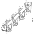
- FIG. 1 is a schematic illustration in perspective view of a flight surface actuator according to an embodiment of the present invention.
- the actuator comprises four eccentric cam mechanisms 1 that in use are mounted a structural element, such as the front spar of an aircraft wing (not shown). Pivotally connected to the eccentric cam mechanisms 1 are lever arms 3 which are in turn connected to the aircraft flight surface being controlled, for example a wing flap.
- a gear box 5, or other suitable gearing arrangement is connected via a torque tube 7 to the nearest one of the eccentric cam mechanisms 1.
- the gear box 5 is arranged to receive an input shaft (not shown) from a power drive unit and to transmit the rotational drive to the torque tube 7, after either increasing or decreasing the rotational speed.
- Each adjacent eccentric cam mechanism 1 is coupled to one another via subsequent torque tubes 7'. Hence rotational drive from the gearbox 5 is transmitted to each of the eccentric cam mechanisms 1 that together form a single actuator.
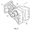
- FIG. 2 A perspective view of one of the eccentric cam mechanisms 1 and lever arm 3 shown in Figure 1 is illustrated in Figure 2.
- the eccentric cam mechanism 1 consists of a bracket 10 that in use is mounted to the front spar of an aircraft wing.
- the bracket 10 supports the actual eccentric cam (not visible in Figure 2) in a pair of bearings 12.
- the eccentric cam itself in turn has a bearing around its periphery that guides and supports a link element 14.
- the lever arm 3 is pivotally connected using further bearings to both the bracket 10 and link element 14.
- the lever arm 3 forms the attachment and hinge for the flight control surface.
- Figures 3a to 3f schematically illustrate the eccentric cam and lever assembly at each extent of a maximum permitted movement ( Figures 3a and 3f) and at intermediate positions.
- Figures 3a and 3f schematically illustrate the eccentric cam and lever assembly at each extent of a maximum permitted movement
- Figures 3a and 3f schematically illustrate the eccentric cam and lever assembly at each extent of a maximum permitted movement
- Figure 3a only one half of the bracket 10 is shown for clarity.
- the actual eccentric cam 20 is therefore clearly illustrated, together with its supporting bearing 12.
- the bearing 22 that supports and guides the link element 14 around the periphery of the eccentric cam 20.
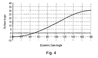
- rotation of the eccentric cam through 180° causes the lever arm 3 to move through an arc of 35°, with one end of the permitted travel being arranged such that the lever arm 3 is at an angle of -5° to the vertical and being at an angle of +30° at the other extent of the travel (Figure 3f).
- FIG. 5 A cross-sectional view of an eccentric cam mechanism and connecting torque tube is shown in Figure 5.
- the bracket 10 is shown supporting the eccentric cam 20 via bearings 12.
- the link element 14 is supported on the eccentric cam 20 by bearings 22.
- the connecting torque tube 7 and 7' are hollow cylindrical tubes that are connected by a spline arrangement to the eccentric cam 20 itself.
- further torque tubes 50 and 50' that are arranged concentrically within the outer torque tubes 7 and 7'.
- the further torque tubes 50 and 50' are connected via a similar spline arrangement to a through drive shaft 52 that is mounted on bearings within the eccentric cam 20. The function of the further torque tubes 50 and through drive shaft 52 will be described in more detail with reference to Figure 7.
- one or more of the bearings are preferably either rolling element bearings, plain bearings, spherical plain bearings or spherical rolling element bearings.
- each actuator assembly comprises a gear arrangement 5 and a number of eccentric cam assemblies 1 and lever arms 3, with interconnecting torque tubes 7 and 7'.
- Figure 1 illustrates four eccentric cam assemblies 1 and lever arms 3, it will be appreciated that any number of such assemblies may form a single actuator.
- the choice of the number of eccentric cam assemblies and lever arms may be made to optimise the distribution of forces through both the aircraft flight control surface and the wing spar to which the assemblies 1 are connected.
- the facility to increase or decrease the number of eccentric cam assemblies enables tailoring of the load distribution into the control surface and wing spar to meet structural limitations.
- each wing will include more than a single flight control surface.
- each flight control surface may be actuated by one or more individual actuators, each actuator being of the kind illustrated in Figure 1.
- Figure 7 illustrates an actuator system including a number of individual control surface actuators.
- each individual flight control surface 80 is controlled by two individual actuators 82, each having a gearbox 5 and four connected eccentric cam and lever arm assemblies 1, 3.
- Providing rotational drive to each of the gearboxes 5 is a power drive unit 84, which is in turn driven by a hydraulic motor 86. Rotational drive from the power drive unit 84 is output via torque tube 50.
- the torque tube 50 is concentric and internal to the torque tubes 7 interconnecting the eccentric cam assemblies 1 of any particular actuator. Rotational drive from the power drive unit is therefore transmitted via the concentric torque tubes 50 and the through drive shaft 52 to each gearbox 5 of each actuator in an uninterrupted manner.
- Each gearbox 5 has its input connected to a torque tube 50 such that the rotational drive imparted from the power drive unit is transferred to the torque tube 7 of the respective actuator assembly.
- Embodiments of the present invention therefore provide an aircraft flight surface actuator and actuator system that typically has a lower weight compared to known actuator systems and also permits the flexible distribution of load into the flight control surface and static part of the aircraft to which the control surface is attached, the flexibility being achieved by altering the number and spacing of the eccentric cam mechanisms. Further advantage of the actuator according to embodiments of the present invention it that it exhibits a high overall mechanical efficiency that allows lower torques to be applied compared to other actuating systems, resulting in the use of smaller torque tubes and power drive units.
Landscapes
- Engineering & Computer Science (AREA)
- Mechanical Engineering (AREA)
- Automation & Control Theory (AREA)
- Aviation & Aerospace Engineering (AREA)
- Transmission Devices (AREA)
- Details Of Aerials (AREA)
- Mechanical Control Devices (AREA)
Claims (7)
- Flugzeug-Flugflächenstellantriebssystem, das folgendes aufweist:eine Vielzahl von Flugzeug-Flugflächenstellantrieben (82), wobei jeder Flugflächenstellantrieb ein Getriebe (5) und eine Vielzahl von exzentrischen Nockenmechanismen (13) aufweist; undeine Kraftantriebseinheit (84, 86), wobei jedes Getriebe der Flugflächenstellantriebe durch ein erstes Drehmomentrohr (50) mit der Kraftantriebseinheit gekoppelt ist, wodurch von der Kraftantriebseinheit auf jedes Getriebe eine Drehantriebskraft übertragen werden kann, dadurch gekennzeichnet, dass:jeder exzentrische Nockenmechanismus (13) einen exzentrischen Nocken aufweist, der mit einer Hebelanordnung (3) zusammenarbeitet, wobei die Hebelanordnung angeordnet ist, um mit einer Flugfläche gekoppelt zu werden, um eine Bewegung auf die Flugfläche zu übertragen;jeder exzentrische Nockenmechanismus eines Flugflächenstellantriebs mit dem jeweiligen Getriebe (5) durch ein zweites Drehmomentrohr (7) gekoppelt ist, wobei die Drehantriebskraft zu jedem exzentrischen Nockenmechanismus übertragen wird; unddas erste Drehmomentrohr konzentrisch zum zweiten Drehmomentrohr angebracht ist.
- Flugzeug-Flugflächenstellantriebssystem nach Anspruch 1, wobei die Hebelanordnung ein erstes Hebelelement (14) in Eingriff mit dem exzentrischen Nocken und ein zweites Hebelelement (3), das mit dem ersten Element über ein Gelenk verbunden ist, aufweist, wobei das zweite Element derart angeordnet ist, dass es mit der Flugfläche gekoppelt ist.
- Flugzeug-Flugflächenstellantriebssystem nach Anspruch 2, wobei die Gelenkverbindung zwischen dem ersten und dem zweiten Hebelelement derart angeordnet ist, dass zugelassen ist, dass eine axiale Fehlausrichtung zwischen dem ersten und dem zweiten Hebelelement auftritt.
- Flugzeug-Flugflächenstellantriebssystem nach Anspruch 2 oder 3, wobei eine Eingriffseinrichtung zwischen dem ersten Hebelelement (14) und dem exzentrischen Nocken vorgesehen ist, wobei die Eingriffseinrichtung derart angeordnet ist, dass eine axiale Fehlausrichtung zwischen dem ersten Hebelelement und dem exzentrischen Nocken zugelassen ist.
- Flugzeug-Flugflächenstellantriebssystem nach Anspruch 3 oder 4, wobei die Drehgelenkverbindung zwischen dem ersten und dem zweiten Hebelelement und/oder der Eingriffseinrichtung (12) zwischen dem ersten Hebelelement und dem exzentrischen Nocken entweder ein Wälzelementlager, ein Radiallager, ein sphärisches Radiallager oder ein sphärisches Wälzelementlager aufweist.
- Flugzeug-Flugflächenstellantriebssystem nach einem der Ansprüche 2 bis 5, wobei der exzentrische Nocken derart angeordnet ist, dass er sich über im Wesentlichen 180° dreht.
- Flugzeug-Flugflächenstellantriebssystem nach einem der Ansprüche 2 bis 6, wobei bei jedem Ausmaß einer Drehung des exzentrischen Nockens die Gelenkstelle zwischen dem ersten und dem zweiten Hebelelement und der Drehpunkt des exzentrischen Nockens mit einer Symmetrielinie des exzentrischen Nockens übereinstimmen, wobei ein Drehmoment von im Wesentlichen Null vom ersten Hebelelement zum exzentrischen Nocken übertragen werden kann.
Applications Claiming Priority (4)
| Application Number | Priority Date | Filing Date | Title |
|---|---|---|---|
| GB0215522 | 2002-07-04 | ||
| GBGB0215522.4A GB0215522D0 (en) | 2002-07-04 | 2002-07-04 | Flight surface actuator |
| GB0305012 | 2003-03-05 | ||
| GB0305012A GB2390344B (en) | 2002-07-04 | 2003-03-05 | Flight surface actuator |
Publications (3)
| Publication Number | Publication Date |
|---|---|
| EP1380500A2 EP1380500A2 (de) | 2004-01-14 |
| EP1380500A3 EP1380500A3 (de) | 2004-01-21 |
| EP1380500B1 true EP1380500B1 (de) | 2006-12-20 |
Family
ID=29738097
Family Applications (1)
| Application Number | Title | Priority Date | Filing Date |
|---|---|---|---|
| EP03253588A Expired - Lifetime EP1380500B1 (de) | 2002-07-04 | 2003-06-06 | Stellantrieb für Flugzeugsteuerflächen |
Country Status (4)
| Country | Link |
|---|---|
| US (1) | US6802475B2 (de) |
| EP (1) | EP1380500B1 (de) |
| AT (1) | ATE348753T1 (de) |
| DE (1) | DE60310483T2 (de) |
Families Citing this family (36)
| Publication number | Priority date | Publication date | Assignee | Title |
|---|---|---|---|---|
| US7243881B2 (en) | 2003-06-03 | 2007-07-17 | The Boeing Company | Multi-function trailing edge devices and associated methods |
| US6799739B1 (en) | 2003-11-24 | 2004-10-05 | The Boeing Company | Aircraft control surface drive system and associated methods |
| US7424350B2 (en) | 2004-02-02 | 2008-09-09 | The Boeing Company | Vehicle control systems and corresponding sizing methods |
| US7357358B2 (en) | 2004-02-27 | 2008-04-15 | The Boeing Company | Aircraft leading edge device systems and corresponding sizing methods |
| US7270305B2 (en) | 2004-06-15 | 2007-09-18 | The Boeing Company | Aircraft leading edge apparatuses and corresponding methods |
| US7494094B2 (en) | 2004-09-08 | 2009-02-24 | The Boeing Company | Aircraft wing systems for providing differential motion to deployable lift devices |
| US7264206B2 (en) | 2004-09-30 | 2007-09-04 | The Boeing Company | Leading edge flap apparatuses and associated methods |
| US7322547B2 (en) | 2005-01-31 | 2008-01-29 | The Boeing Company | Aerospace vehicle leading edge slat devices and corresponding methods |
| US7338018B2 (en) | 2005-02-04 | 2008-03-04 | The Boeing Company | Systems and methods for controlling aircraft flaps and spoilers |
| US7309043B2 (en) | 2005-04-27 | 2007-12-18 | The Boeing Company | Actuation device positioning systems and associated methods, including aircraft spoiler droop systems |
| US7300021B2 (en) | 2005-05-20 | 2007-11-27 | The Boeing Company | Aerospace vehicle fairing systems and associated methods |
| US7721999B2 (en) | 2005-05-20 | 2010-05-25 | The Boeing Company | Aerospace vehicle fairing systems and associated methods |
| US7367530B2 (en) | 2005-06-21 | 2008-05-06 | The Boeing Company | Aerospace vehicle yaw generating systems and associated methods |
| US7500641B2 (en) | 2005-08-10 | 2009-03-10 | The Boeing Company | Aerospace vehicle flow body systems and associated methods |
| US7475854B2 (en) | 2005-11-21 | 2009-01-13 | The Boeing Company | Aircraft trailing edge devices, including devices with non-parallel motion paths, and associated methods |
| US7708231B2 (en) | 2005-11-21 | 2010-05-04 | The Boeing Company | Aircraft trailing edge devices, including devices having forwardly positioned hinge lines, and associated methods |
| US7322545B2 (en) * | 2005-12-29 | 2008-01-29 | The Boeing Company | Structural mechanism for unlocking and engaging a controllable surface on a hinged platform (wing) |
| US7578484B2 (en) | 2006-06-14 | 2009-08-25 | The Boeing Company | Link mechanisms for gapped rigid krueger flaps, and associated systems and methods |
| US7954769B2 (en) | 2007-12-10 | 2011-06-07 | The Boeing Company | Deployable aerodynamic devices with reduced actuator loads, and related systems and methods |
| US7766282B2 (en) | 2007-12-11 | 2010-08-03 | The Boeing Company | Trailing edge device catchers and associated systems and methods |
| US8047765B2 (en) * | 2008-08-29 | 2011-11-01 | General Electric Company | Device, system and method for thermally activated displacement |
| US8118260B2 (en) * | 2008-10-31 | 2012-02-21 | Airbus Operations S.L. | Fitting for trimming a horizontal stabilizer of an aircraft |
| JP5562575B2 (ja) * | 2009-04-27 | 2014-07-30 | ナブテスコ株式会社 | 航空機用アクチュエータ |
| FR2946617B1 (fr) * | 2009-06-10 | 2012-11-16 | Sagem Defense Securite | Dispositif d'actionnement d'une gouverne d'aeronef. |
| US8382045B2 (en) | 2009-07-21 | 2013-02-26 | The Boeing Company | Shape-changing control surface |
| EP2605962B1 (de) * | 2010-08-20 | 2016-06-01 | Csir | Trägflächensteuerungssystem |
| US9061753B2 (en) | 2012-11-29 | 2015-06-23 | The Boeing Company | Hinged panel operation systems and methods |
| FR3016607B1 (fr) * | 2014-01-20 | 2016-01-22 | Sagem Defense Securite | Actionneur de commande d'un plan horizontal de stabilisation d'un aeronef |
| FR3022215B1 (fr) | 2014-06-13 | 2016-05-27 | Sagem Defense Securite | Actionneur pour surface de vol et ensemble de guidage d'un aeronef comprenant un tel actionneur |
| US20170106970A1 (en) | 2015-10-15 | 2017-04-20 | The Boeing Company | Composite failsafe torque tube |
| CN107264778B (zh) * | 2016-04-08 | 2019-06-25 | 陕西飞机工业(集团)有限公司 | 一种尾翼方向舵轴承座连接结构 |
| US10766602B2 (en) * | 2017-11-01 | 2020-09-08 | The Boeing Company | Mechanical droop for spoiler operation |
| US11001371B2 (en) * | 2018-08-07 | 2021-05-11 | The Boeing Company | Hydraulic droop control for aircraft wing |
| US10663041B2 (en) | 2018-08-14 | 2020-05-26 | Hamilton Sunstrand Corporation | Jam-tolerant electric linear actuator |
| EP3972897B1 (de) * | 2019-05-22 | 2023-04-26 | Moog Inc. | Vorgespannte drehmomentwelle und damit hergestellte flugsteuerungsantriebsanlage |
| EP3858728B1 (de) * | 2020-01-31 | 2024-05-01 | Goodrich Actuation Systems Limited | Klappenbetätigungsanordnung |
Family Cites Families (13)
| Publication number | Priority date | Publication date | Assignee | Title |
|---|---|---|---|---|
| FR887029A (fr) * | 1941-10-22 | 1943-11-02 | Askania Werke Ag | Dispositif d'accouplement pour l'embrayage de servo-moteurs de gouvernes à la tringlerie de pilotage d'un mobile tel qu'un avion |
| FR1392727A (fr) | 1964-02-25 | 1965-03-19 | Rotorcraft S A Proprietary Ltd | Aéronef à aile tournante |
| DE2909244C2 (de) | 1979-03-09 | 1982-12-23 | Dornier Gmbh, 7990 Friedrichshafen | Verfahren und Vorrichtung zur Rollsteuerung von Luftfahrzeugen mittels Störklappen |
| US4362067A (en) * | 1980-08-21 | 1982-12-07 | The Garrett Corporation | Variable authority trim mixer |
| US4533096A (en) * | 1982-12-30 | 1985-08-06 | The Boeing Company | High lift system control assembly |
| GB2138756B (en) | 1983-04-26 | 1986-07-16 | Boeing Co | Wing leading edge slat |
| FR2547270B1 (fr) * | 1983-06-10 | 1985-09-06 | Boeing Co | Mecanisme d'extension et de retraction pour un volet de bord d'attaque d'une aile d'avion |
| DE3702294C1 (de) * | 1987-01-27 | 1988-04-14 | Messerschmitt Boelkow Blohm | Stelleinrichtung fuer Tragflaechenklappen von Flugzeugen |
| FR2770826B1 (fr) * | 1997-11-07 | 2000-01-07 | Eurocopter France | Pale de rotor a volet orientable |
| JP2907335B1 (ja) * | 1998-03-24 | 1999-06-21 | 株式会社コミュータヘリコプタ先進技術研究所 | ロータブレードのフラップ駆動装置 |
| JP3053620B1 (ja) * | 1999-02-25 | 2000-06-19 | 株式会社コミュータヘリコプタ先進技術研究所 | ロ―タブレ―ドのフラップ駆動装置 |
| FR2809080B1 (fr) * | 2000-05-22 | 2002-08-30 | Lucas Aerospace Fcs | Dispositif d'actionnement, notamment pour commande de vol d'aeronef |
| DE10055961B4 (de) * | 2000-11-11 | 2004-09-09 | Eads Deutschland Gmbh | Variabler Flügelbereich mit einstellbarer, sich in Spannweiten-Richtung erstreckender Profilform |
-
2003
- 2003-05-16 US US10/439,527 patent/US6802475B2/en not_active Expired - Lifetime
- 2003-06-06 DE DE60310483T patent/DE60310483T2/de not_active Expired - Lifetime
- 2003-06-06 AT AT03253588T patent/ATE348753T1/de not_active IP Right Cessation
- 2003-06-06 EP EP03253588A patent/EP1380500B1/de not_active Expired - Lifetime
Also Published As
| Publication number | Publication date |
|---|---|
| ATE348753T1 (de) | 2007-01-15 |
| US20040004163A1 (en) | 2004-01-08 |
| EP1380500A2 (de) | 2004-01-14 |
| US6802475B2 (en) | 2004-10-12 |
| DE60310483T2 (de) | 2007-11-29 |
| DE60310483D1 (de) | 2007-02-01 |
| EP1380500A3 (de) | 2004-01-21 |
Similar Documents
| Publication | Publication Date | Title |
|---|---|---|
| EP1380500B1 (de) | Stellantrieb für Flugzeugsteuerflächen | |
| US6030177A (en) | Drive system for a variable diameter tilt rotor | |
| EP1794051B1 (de) | Kompaktes pylonbetätigungssystem für schwenkrotorflugzeug | |
| EP0448672B1 (de) | Antriebssystem für schwenkbaren rotor | |
| JP2768826B2 (ja) | 回転翼型航空機の尾部回転翼のダクトファンおよびピッチ制御装置 | |
| US4804352A (en) | Link-type rotary coupling | |
| US7309043B2 (en) | Actuation device positioning systems and associated methods, including aircraft spoiler droop systems | |
| US20090092493A1 (en) | Variable pitch rotor blade with double flexible retention elements | |
| EP2678221B1 (de) | Blattwinkelteuerungssystem mit rückkoppelungstaumelscheibe | |
| CA2113179C (en) | Ducted tail rotor for rotary wing aircraft providing torque reaction and yaw attitude control | |
| US10486806B2 (en) | Pivot systems for tiltwing aircraft | |
| CN110683049B (zh) | 一种用于小型倾转旋翼机的桨毂装置 | |
| GB2406884A (en) | Cyclic and collective propeller blade control | |
| US6705570B1 (en) | Arrangement and associated system having an actuator and a tubular flap-drive member about the actuator | |
| US3589835A (en) | Variable stiffness rotor | |
| US20040169108A1 (en) | Fluid conduit for use with hydraulic actuator | |
| CA1250271A (en) | Aircraft wing section movement apparatus | |
| JPS6160396A (ja) | ロータシステム | |
| GB2390344A (en) | Flight surface actuator | |
| CN115916641B (zh) | 用于能够悬停的航空器的旋翼 | |
| CN116552786A (zh) | 一种滚翼装置及飞行器 | |
| US12576964B1 (en) | Helicopter pitch controls | |
| EP4306409A1 (de) | Drehgelenkverbindung | |
| EP3998206B1 (de) | Luftfahrzeug | |
| CN116062163A (zh) | 一种旋翼飞行器及其变负扭桨叶 |
Legal Events
| Date | Code | Title | Description |
|---|---|---|---|
| PUAI | Public reference made under article 153(3) epc to a published international application that has entered the european phase |
Free format text: ORIGINAL CODE: 0009012 |
|
| PUAL | Search report despatched |
Free format text: ORIGINAL CODE: 0009013 |
|
| AK | Designated contracting states |
Kind code of ref document: A2 Designated state(s): AT BE BG CH CY CZ DE DK EE ES FI FR GB GR HU IE IT LI LU MC NL PT RO SE SI SK TR |
|
| AX | Request for extension of the european patent |
Extension state: AL LT LV MK |
|
| AK | Designated contracting states |
Kind code of ref document: A3 Designated state(s): AT BE BG CH CY CZ DE DK EE ES FI FR GB GR HU IE IT LI LU MC NL PT RO SE SI SK TR |
|
| AX | Request for extension of the european patent |
Extension state: AL LT LV MK |
|
| 17P | Request for examination filed |
Effective date: 20040326 |
|
| 17Q | First examination report despatched |
Effective date: 20040517 |
|
| AKX | Designation fees paid |
Designated state(s): AT BE BG CH CY CZ DE DK EE ES FI FR GB GR HU IE IT LI LU MC NL PT RO SE SI SK TR |
|
| GRAP | Despatch of communication of intention to grant a patent |
Free format text: ORIGINAL CODE: EPIDOSNIGR1 |
|
| GRAS | Grant fee paid |
Free format text: ORIGINAL CODE: EPIDOSNIGR3 |
|
| GRAA | (expected) grant |
Free format text: ORIGINAL CODE: 0009210 |
|
| AK | Designated contracting states |
Kind code of ref document: B1 Designated state(s): AT BE BG CH CY CZ DE DK EE ES FI FR GR HU IE IT LI LU MC NL PT RO SE SI SK TR |
|
| PG25 | Lapsed in a contracting state [announced via postgrant information from national office to epo] |
Ref country code: AT Free format text: LAPSE BECAUSE OF FAILURE TO SUBMIT A TRANSLATION OF THE DESCRIPTION OR TO PAY THE FEE WITHIN THE PRESCRIBED TIME-LIMIT Effective date: 20061220 Ref country code: BE Free format text: LAPSE BECAUSE OF FAILURE TO SUBMIT A TRANSLATION OF THE DESCRIPTION OR TO PAY THE FEE WITHIN THE PRESCRIBED TIME-LIMIT Effective date: 20061220 Ref country code: DK Free format text: LAPSE BECAUSE OF FAILURE TO SUBMIT A TRANSLATION OF THE DESCRIPTION OR TO PAY THE FEE WITHIN THE PRESCRIBED TIME-LIMIT Effective date: 20061220 Ref country code: CH Free format text: LAPSE BECAUSE OF FAILURE TO SUBMIT A TRANSLATION OF THE DESCRIPTION OR TO PAY THE FEE WITHIN THE PRESCRIBED TIME-LIMIT Effective date: 20061220 Ref country code: NL Free format text: LAPSE BECAUSE OF FAILURE TO SUBMIT A TRANSLATION OF THE DESCRIPTION OR TO PAY THE FEE WITHIN THE PRESCRIBED TIME-LIMIT Effective date: 20061220 Ref country code: RO Free format text: LAPSE BECAUSE OF FAILURE TO SUBMIT A TRANSLATION OF THE DESCRIPTION OR TO PAY THE FEE WITHIN THE PRESCRIBED TIME-LIMIT Effective date: 20061220 Ref country code: SI Free format text: LAPSE BECAUSE OF FAILURE TO SUBMIT A TRANSLATION OF THE DESCRIPTION OR TO PAY THE FEE WITHIN THE PRESCRIBED TIME-LIMIT Effective date: 20061220 Ref country code: FI Free format text: LAPSE BECAUSE OF FAILURE TO SUBMIT A TRANSLATION OF THE DESCRIPTION OR TO PAY THE FEE WITHIN THE PRESCRIBED TIME-LIMIT Effective date: 20061220 Ref country code: CZ Free format text: LAPSE BECAUSE OF FAILURE TO SUBMIT A TRANSLATION OF THE DESCRIPTION OR TO PAY THE FEE WITHIN THE PRESCRIBED TIME-LIMIT Effective date: 20061220 Ref country code: SK Free format text: LAPSE BECAUSE OF FAILURE TO SUBMIT A TRANSLATION OF THE DESCRIPTION OR TO PAY THE FEE WITHIN THE PRESCRIBED TIME-LIMIT Effective date: 20061220 Ref country code: LI Free format text: LAPSE BECAUSE OF FAILURE TO SUBMIT A TRANSLATION OF THE DESCRIPTION OR TO PAY THE FEE WITHIN THE PRESCRIBED TIME-LIMIT Effective date: 20061220 |
|
| REG | Reference to a national code |
Ref country code: CH Ref legal event code: EP |
|
| REF | Corresponds to: |
Ref document number: 60310483 Country of ref document: DE Date of ref document: 20070201 Kind code of ref document: P |
|
| REG | Reference to a national code |
Ref country code: IE Ref legal event code: FG4D |
|
| PG25 | Lapsed in a contracting state [announced via postgrant information from national office to epo] |
Ref country code: BG Free format text: LAPSE BECAUSE OF FAILURE TO SUBMIT A TRANSLATION OF THE DESCRIPTION OR TO PAY THE FEE WITHIN THE PRESCRIBED TIME-LIMIT Effective date: 20070320 |
|
| PG25 | Lapsed in a contracting state [announced via postgrant information from national office to epo] |
Ref country code: ES Free format text: LAPSE BECAUSE OF FAILURE TO SUBMIT A TRANSLATION OF THE DESCRIPTION OR TO PAY THE FEE WITHIN THE PRESCRIBED TIME-LIMIT Effective date: 20070331 |
|
| REG | Reference to a national code |
Ref country code: SE Ref legal event code: TRGR |
|
| PG25 | Lapsed in a contracting state [announced via postgrant information from national office to epo] |
Ref country code: PT Free format text: LAPSE BECAUSE OF FAILURE TO SUBMIT A TRANSLATION OF THE DESCRIPTION OR TO PAY THE FEE WITHIN THE PRESCRIBED TIME-LIMIT Effective date: 20070424 |
|
| NLV1 | Nl: lapsed or annulled due to failure to fulfill the requirements of art. 29p and 29m of the patents act | ||
| ET | Fr: translation filed | ||
| REG | Reference to a national code |
Ref country code: CH Ref legal event code: PL |
|
| PLBE | No opposition filed within time limit |
Free format text: ORIGINAL CODE: 0009261 |
|
| STAA | Information on the status of an ep patent application or granted ep patent |
Free format text: STATUS: NO OPPOSITION FILED WITHIN TIME LIMIT |
|
| 26N | No opposition filed |
Effective date: 20070921 |
|
| PG25 | Lapsed in a contracting state [announced via postgrant information from national office to epo] |
Ref country code: MC Free format text: LAPSE BECAUSE OF NON-PAYMENT OF DUE FEES Effective date: 20070630 |
|
| PG25 | Lapsed in a contracting state [announced via postgrant information from national office to epo] |
Ref country code: GR Free format text: LAPSE BECAUSE OF FAILURE TO SUBMIT A TRANSLATION OF THE DESCRIPTION OR TO PAY THE FEE WITHIN THE PRESCRIBED TIME-LIMIT Effective date: 20070321 |
|
| PG25 | Lapsed in a contracting state [announced via postgrant information from national office to epo] |
Ref country code: IE Free format text: LAPSE BECAUSE OF NON-PAYMENT OF DUE FEES Effective date: 20070606 |
|
| REG | Reference to a national code |
Ref country code: FR Ref legal event code: TP |
|
| PG25 | Lapsed in a contracting state [announced via postgrant information from national office to epo] |
Ref country code: EE Free format text: LAPSE BECAUSE OF FAILURE TO SUBMIT A TRANSLATION OF THE DESCRIPTION OR TO PAY THE FEE WITHIN THE PRESCRIBED TIME-LIMIT Effective date: 20061220 |
|
| PG25 | Lapsed in a contracting state [announced via postgrant information from national office to epo] |
Ref country code: LU Free format text: LAPSE BECAUSE OF NON-PAYMENT OF DUE FEES Effective date: 20070606 Ref country code: CY Free format text: LAPSE BECAUSE OF FAILURE TO SUBMIT A TRANSLATION OF THE DESCRIPTION OR TO PAY THE FEE WITHIN THE PRESCRIBED TIME-LIMIT Effective date: 20061220 |
|
| PG25 | Lapsed in a contracting state [announced via postgrant information from national office to epo] |
Ref country code: TR Free format text: LAPSE BECAUSE OF FAILURE TO SUBMIT A TRANSLATION OF THE DESCRIPTION OR TO PAY THE FEE WITHIN THE PRESCRIBED TIME-LIMIT Effective date: 20061220 Ref country code: HU Free format text: LAPSE BECAUSE OF FAILURE TO SUBMIT A TRANSLATION OF THE DESCRIPTION OR TO PAY THE FEE WITHIN THE PRESCRIBED TIME-LIMIT Effective date: 20070621 |
|
| REG | Reference to a national code |
Ref country code: FR Ref legal event code: TP |
|
| PGFP | Annual fee paid to national office [announced via postgrant information from national office to epo] |
Ref country code: SE Payment date: 20110613 Year of fee payment: 9 |
|
| PG25 | Lapsed in a contracting state [announced via postgrant information from national office to epo] |
Ref country code: IT Free format text: LAPSE BECAUSE OF NON-PAYMENT OF DUE FEES Effective date: 20110606 |
|
| PGFP | Annual fee paid to national office [announced via postgrant information from national office to epo] |
Ref country code: IT Payment date: 20111228 Year of fee payment: 9 |
|
| REG | Reference to a national code |
Ref country code: SE Ref legal event code: EUG |
|
| PG25 | Lapsed in a contracting state [announced via postgrant information from national office to epo] |
Ref country code: IT Free format text: LAPSE BECAUSE OF NON-PAYMENT OF DUE FEES Effective date: 20120606 Ref country code: SE Free format text: LAPSE BECAUSE OF NON-PAYMENT OF DUE FEES Effective date: 20120607 |
|
| REG | Reference to a national code |
Ref country code: FR Ref legal event code: PLFP Year of fee payment: 14 |
|
| REG | Reference to a national code |
Ref country code: FR Ref legal event code: PLFP Year of fee payment: 15 |
|
| REG | Reference to a national code |
Ref country code: FR Ref legal event code: PLFP Year of fee payment: 16 |
|
| PGFP | Annual fee paid to national office [announced via postgrant information from national office to epo] |
Ref country code: DE Payment date: 20200721 Year of fee payment: 18 Ref country code: FR Payment date: 20200721 Year of fee payment: 18 |
|
| REG | Reference to a national code |
Ref country code: DE Ref legal event code: R119 Ref document number: 60310483 Country of ref document: DE |
|
| PG25 | Lapsed in a contracting state [announced via postgrant information from national office to epo] |
Ref country code: DE Free format text: LAPSE BECAUSE OF NON-PAYMENT OF DUE FEES Effective date: 20220101 |
|
| PG25 | Lapsed in a contracting state [announced via postgrant information from national office to epo] |
Ref country code: FR Free format text: LAPSE BECAUSE OF NON-PAYMENT OF DUE FEES Effective date: 20210630 |