EP1380699A2 - Schallabsorbierendes Paneel - Google Patents
Schallabsorbierendes Paneel Download PDFInfo
- Publication number
- EP1380699A2 EP1380699A2 EP03014226A EP03014226A EP1380699A2 EP 1380699 A2 EP1380699 A2 EP 1380699A2 EP 03014226 A EP03014226 A EP 03014226A EP 03014226 A EP03014226 A EP 03014226A EP 1380699 A2 EP1380699 A2 EP 1380699A2
- Authority
- EP
- European Patent Office
- Prior art keywords
- slots
- front panel
- plate
- element according
- sound
- Prior art date
- Legal status (The legal status is an assumption and is not a legal conclusion. Google has not performed a legal analysis and makes no representation as to the accuracy of the status listed.)
- Granted
Links
- 238000010521 absorption reaction Methods 0.000 claims description 6
- 230000015572 biosynthetic process Effects 0.000 claims 1
- 238000004519 manufacturing process Methods 0.000 description 4
- 238000003801 milling Methods 0.000 description 4
- 239000002023 wood Substances 0.000 description 3
- 230000000694 effects Effects 0.000 description 2
- 239000000463 material Substances 0.000 description 2
- 229920000877 Melamine resin Polymers 0.000 description 1
- 239000004640 Melamine resin Substances 0.000 description 1
- 239000004568 cement Substances 0.000 description 1
- 230000001419 dependent effect Effects 0.000 description 1
- 238000005553 drilling Methods 0.000 description 1
- 230000008030 elimination Effects 0.000 description 1
- 238000003379 elimination reaction Methods 0.000 description 1
- 210000003746 feather Anatomy 0.000 description 1
- 239000000835 fiber Substances 0.000 description 1
- 229910052602 gypsum Inorganic materials 0.000 description 1
- 239000010440 gypsum Substances 0.000 description 1
- 230000001771 impaired effect Effects 0.000 description 1
- 238000009434 installation Methods 0.000 description 1
- 238000009413 insulation Methods 0.000 description 1
- 230000007246 mechanism Effects 0.000 description 1
- 238000000034 method Methods 0.000 description 1
- 238000002310 reflectometry Methods 0.000 description 1
- 238000007493 shaping process Methods 0.000 description 1
- 239000007787 solid Substances 0.000 description 1
Images
Classifications
-
- E—FIXED CONSTRUCTIONS
- E04—BUILDING
- E04F—FINISHING WORK ON BUILDINGS, e.g. STAIRS, FLOORS
- E04F13/00—Coverings or linings, e.g. for walls or ceilings
- E04F13/07—Coverings or linings, e.g. for walls or ceilings composed of covering or lining elements; Sub-structures therefor; Fastening means therefor
- E04F13/08—Coverings or linings, e.g. for walls or ceilings composed of covering or lining elements; Sub-structures therefor; Fastening means therefor composed of a plurality of similar covering or lining elements
- E04F13/0867—Coverings or linings, e.g. for walls or ceilings composed of covering or lining elements; Sub-structures therefor; Fastening means therefor composed of a plurality of similar covering or lining elements having acoustic absorption means on the visible surface
-
- E—FIXED CONSTRUCTIONS
- E04—BUILDING
- E04B—GENERAL BUILDING CONSTRUCTIONS; WALLS, e.g. PARTITIONS; ROOFS; FLOORS; CEILINGS; INSULATION OR OTHER PROTECTION OF BUILDINGS
- E04B1/00—Constructions in general; Structures which are not restricted either to walls, e.g. partitions, or floors or ceilings or roofs
- E04B1/62—Insulation or other protection; Elements or use of specified material therefor
- E04B1/74—Heat, sound or noise insulation, absorption, or reflection; Other building methods affording favourable thermal or acoustical conditions, e.g. accumulating of heat within walls
- E04B1/82—Heat, sound or noise insulation, absorption, or reflection; Other building methods affording favourable thermal or acoustical conditions, e.g. accumulating of heat within walls specifically with respect to sound only
- E04B1/84—Sound-absorbing elements
- E04B1/86—Sound-absorbing elements slab-shaped
-
- G—PHYSICS
- G10—MUSICAL INSTRUMENTS; ACOUSTICS
- G10K—SOUND-PRODUCING DEVICES; METHODS OR DEVICES FOR PROTECTING AGAINST, OR FOR DAMPING, NOISE OR OTHER ACOUSTIC WAVES IN GENERAL; ACOUSTICS NOT OTHERWISE PROVIDED FOR
- G10K11/00—Methods or devices for transmitting, conducting or directing sound in general; Methods or devices for protecting against, or for damping, noise or other acoustic waves in general
- G10K11/16—Methods or devices for protecting against, or for damping, noise or other acoustic waves in general
-
- E—FIXED CONSTRUCTIONS
- E04—BUILDING
- E04B—GENERAL BUILDING CONSTRUCTIONS; WALLS, e.g. PARTITIONS; ROOFS; FLOORS; CEILINGS; INSULATION OR OTHER PROTECTION OF BUILDINGS
- E04B1/00—Constructions in general; Structures which are not restricted either to walls, e.g. partitions, or floors or ceilings or roofs
- E04B1/62—Insulation or other protection; Elements or use of specified material therefor
- E04B1/74—Heat, sound or noise insulation, absorption, or reflection; Other building methods affording favourable thermal or acoustical conditions, e.g. accumulating of heat within walls
- E04B1/82—Heat, sound or noise insulation, absorption, or reflection; Other building methods affording favourable thermal or acoustical conditions, e.g. accumulating of heat within walls specifically with respect to sound only
- E04B1/84—Sound-absorbing elements
- E04B2001/8457—Solid slabs or blocks
- E04B2001/8461—Solid slabs or blocks layered
-
- E—FIXED CONSTRUCTIONS
- E04—BUILDING
- E04B—GENERAL BUILDING CONSTRUCTIONS; WALLS, e.g. PARTITIONS; ROOFS; FLOORS; CEILINGS; INSULATION OR OTHER PROTECTION OF BUILDINGS
- E04B1/00—Constructions in general; Structures which are not restricted either to walls, e.g. partitions, or floors or ceilings or roofs
- E04B1/62—Insulation or other protection; Elements or use of specified material therefor
- E04B1/74—Heat, sound or noise insulation, absorption, or reflection; Other building methods affording favourable thermal or acoustical conditions, e.g. accumulating of heat within walls
- E04B1/82—Heat, sound or noise insulation, absorption, or reflection; Other building methods affording favourable thermal or acoustical conditions, e.g. accumulating of heat within walls specifically with respect to sound only
- E04B1/84—Sound-absorbing elements
- E04B2001/8457—Solid slabs or blocks
- E04B2001/8476—Solid slabs or blocks with acoustical cavities, with or without acoustical filling
- E04B2001/848—Solid slabs or blocks with acoustical cavities, with or without acoustical filling the cavities opening onto the face of the element
- E04B2001/849—Groove or slot type openings
-
- E—FIXED CONSTRUCTIONS
- E04—BUILDING
- E04F—FINISHING WORK ON BUILDINGS, e.g. STAIRS, FLOORS
- E04F2203/00—Specially structured or shaped covering, lining or flooring elements not otherwise provided for
- E04F2203/04—Specially structured or shaped covering, lining or flooring elements not otherwise provided for comprising a plurality of internal elongated cavities arranged in substantially parallel rows
Definitions
- the present invention relates to a sound absorbing Element that consists of several layers and at least has recesses in one layer.
- Such sound absorbing elements also as so-called.
- Acoustic panels are referred to in the various embodiments in the prior art known.
- Such plates include configurations with through holes, offset from the visible side, through slits or similar recesses.
- longitudinally and / or transversely grooved plates are known, wherein the front of the plate is grooved lengthways, the back of the The plate, however, is grooved across.
- DE 299 11 495 U1 is a multilayer sound-absorbing element known, the recesses in has at least one layer.
- the known from this three-layer structure are in an intermediate layer parallel slots are provided, the sound is introduced into the component via microperforations.
- EP 0 745 738 B1 discloses a Three-layer solid wood structure to be used, the Grain direction of the cover layers is specified, and wherein has at least one cover layer of grooves in contact with transverse grooves of the one below Middle class.
- the degree is achievable sound absorption depends only on the Number of slots per layer, their slot width and their distances from each other and from which layers of the Elements are provided with slots. In their manufacture is therefore only the milling or planing tool convert or replace. The process steps as such remain unaffected.
- the plate-shaped elements produced in this way can be used for Arrangement of ceilings and walls afterwards accordingly be cut, with the mounting side facing the is formed by the back plate of the element with corresponding connection mechanisms, if necessary under Use of substructures, interacts.
- Such an acoustic element is preferably made of Made of wood materials.
- the Elements according to the present invention so-called MDF (medium Density Fiber) - plates are used.
- MDF medium Density Fiber
- the plates can each be in one piece.
- the slots of the plates are, for example, in one Range of 9 to 12 mm, but are preferably directed according to the desired degree of absorption of each Installation location.
- the slots can be next rectangular cross-sections also other cross-sectional shapes include.
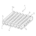
- Element 1 is sandwiched from two congruent layers composed. It comprises a front plate 3 and a back plate 4 that the front plate 3 lies opposite for fastening the element 1 to one Wall, ceiling or the like. A surface of the Front plate 3 forms the visible side 3s of the element 1.
- the front panel is 3 on the one hand, provided with first slots 5 that start from the visible side 3s of the front panel 3 into this Milling or planing have been introduced.
- the front panel has slots 6, which from the side opposite the visible side 3s of the Front plate 3 are introduced into this and the transverse to the Slits 5 run.
- the slots 5 in the front panel 3 are parallel to each other at a certain distance attached, as well as the slots 6, which are transverse to this run.
- the slots 5 and 6 have one Depth that they are training themselves Cut sound passage opening 8. In these Sound passage openings 8, the sound is collected and reflected back and forth, creating a Sound absorption effect occurs.
- the slots 7 which extend up to one Extend depth below the thickness of the back plate 4, i. H. the slots 7 have such a depth that they extend into the front panel 3 so that they cut the transverse slots 6 and so Sound passage openings 8 at the respective Form interfaces.
- the slots 7 and 5 opposite and have essentially the same groove width. It will thus sound passage openings 8 created extend over both plate layers and so the entire Assert the thickness of element 1. This will make them bigger Spaces created in which the sound can be captured. is the element 1 on a substructure of a wall arranged and at a certain distance from it, there are further absorption spaces available for the sound waves Available.
- the embodiment of the element 1 is characterized by a relatively simple constructive design. In doing so first the slots 6 on the visible side 3s opposite side of the front panel 3 by means of a Planer or milling machine introduced into the front panel 3 and then glued the plates 3, 4 together or pressed. By appropriate tool design can then both the slots 7 of the back plate 4 and the Slots 5 of the front panel 3 as well as possible grooves and Feathers on opposite edge sides of the Element 1 can be manufactured in a single operation.
- the individual elements 1 can during assembly tongue and groove connections, not shown, are connected.
Landscapes
- Physics & Mathematics (AREA)
- Acoustics & Sound (AREA)
- Engineering & Computer Science (AREA)
- Architecture (AREA)
- Civil Engineering (AREA)
- Structural Engineering (AREA)
- Electromagnetism (AREA)
- Multimedia (AREA)
- Building Environments (AREA)
- Devices Affording Protection Of Roads Or Walls For Sound Insulation (AREA)
- Soundproofing, Sound Blocking, And Sound Damping (AREA)
- Vehicle Interior And Exterior Ornaments, Soundproofing, And Insulation (AREA)
Abstract
Description
Ein die Nachhallzeiten des Schalls verringerndes Element ist beispielsweise aus der deutschen Offenlegungsschrift DE 195 05 025 bekannt. In dieser ist ein plattenförmiges Element offenbart, dessen Oberseite mit einer Vielzahl von sich parallel in das Element hinein erstreckenden Nuten versehen ist, wohingegen die Rückseite des Elements eine Reihe von Bohrungen aufweist, die auf die jeweilige Nut in der Frontseite ausgerichtet sind, so dass sich entsprechende Schalldurchtrittsöffnungen ergeben. Die Herstellung eines derartigen Elements, insbesondere das Fräsen der Nuten und das Setzen der Bohrungen, erfolgt in vielen einzelnen Arbeitsschritten, was sich als zeit- und kostenintensiv erweist.
Claims (7)
- Mehrschichtiges schallabsorbierendes Element mit Ausnehmungen zumindest in einer Schicht, mit einem zweischichtigen Aufbau umfassend eine Frontplatte (3), die in einem bestimmten Abstand parallel zueinander verlaufende Schlitze (5) an ihrer eine Sichtseite (3s) des Elements (1) bildenden Seite aufweist und eine die Befestigungsseite des Elements (1) bildenden Rückplatte (4), wobei die Frontplatte (3) auf ihrer der Sichtseite (3s) gegenüberliegenden Seite in einem bestimmten Abstand parallel zueinander und im Wesentlichen senkrecht zu den Schlitzen (5) der Sichtseite (3s) der Frontplatte (3) verlaufende Schlitze (6) besitzt, und wobei sich die Schlitze (6) und die Schlitze (5) der Frontplatte (3) unter Ausbildung von Schalldurchtrittsöffnung (8) schneiden.
- Element nach Anspruch 1, gekennzeichnet durch Schlitze (7) in der Rückplatte (4), die in einem bestimmten Abstand parallel zueinander und im wesentlichen senkrecht zu den Schlitzen (6) der Frontplatte (3) verlaufen, wobei sich die Schlitze (7) der Rückplatte (4) von deren Oberfläche bis zu einer Tiefe unterhalb deren Dicke bis in die Frontplatte (3) hinein erstrecken, so dass sich die Schlitze (7) der Rückplatte (4) und die Schlitze (6) der Frontplatte (3) unter Ausbildung einer Schalldurchtrittsöffnung (8) schneiden.
- Element nach Anspruch 2, gekennzeichnet durch Schlitze (5) in der Frontplatte (3) und Schlitze (7) in der Rückplatte (4), die sich einander deckungsgleich gegenüberliegen.
- Element nach Anspruch 3, gekennzeichnet durch Schlitze (5) in der Frontplatte (3) und Schlitze (7) in der Rückplatte (4), die sich einander gegenüberliegen, wobei die Schlitzbreite der Schlitze (7) der Rückplatte (4) größer als die Schlitzbreite der Schlitze (5) der Frontplatte (3) ist.
- Element nach einem der Ansprüche 1 bis 4, gekennzeichnet durch eine Schlitzbreite der Schlitze (5) der Frontplatte (3), die zumindest der Schlitzbreite der Schlitze (6) der Frontplatte (3) entspricht.
- Element nach einem der vorhergehenden Ansprüche, dadurch gekennzeichnet, dass die Schlitzbreite der Schlitze (5) der Frontplatte (3) und/oder der Schlitze (6) der Frontplatte (3) und/oder der Schlitze (7) der Rückplatte (4) sowie die Abstände zwischen den jeweiligen Schlitzen (5, 6, 7) in Abhängigkeit des zu erzielenden Schallabsorptionsgrads ausgelegt sind.
- Element nach einem der vorhergehenden Ansprüche, gekennzeichnet durch eine Nut auf wenigstens einer Kantenseite des Elements (1) und einer komplementär ausgestalteten Feder auf der jeweils gegenüberliegenden Kantenseite des Elements (1).
Applications Claiming Priority (2)
| Application Number | Priority Date | Filing Date | Title |
|---|---|---|---|
| DE20211388U | 2002-07-10 | ||
| DE20211388U DE20211388U1 (de) | 2002-07-10 | 2002-07-10 | Schallabsorbierendes Paneel |
Publications (3)
| Publication Number | Publication Date |
|---|---|
| EP1380699A2 true EP1380699A2 (de) | 2004-01-14 |
| EP1380699A3 EP1380699A3 (de) | 2004-11-17 |
| EP1380699B1 EP1380699B1 (de) | 2007-09-12 |
Family
ID=29594708
Family Applications (1)
| Application Number | Title | Priority Date | Filing Date |
|---|---|---|---|
| EP03014226A Expired - Lifetime EP1380699B1 (de) | 2002-07-10 | 2003-06-25 | Schallabsorbierendes Paneel |
Country Status (4)
| Country | Link |
|---|---|
| EP (1) | EP1380699B1 (de) |
| AT (1) | ATE373149T1 (de) |
| DE (2) | DE20211388U1 (de) |
| ES (1) | ES2290386T3 (de) |
Families Citing this family (1)
| Publication number | Priority date | Publication date | Assignee | Title |
|---|---|---|---|---|
| ES2279722B1 (es) * | 2006-02-03 | 2008-09-01 | Ceramica Saloni, S.A. | Procedimiento de fabricacion de piezas ceramicas con propiedades acusticas y pieza obtenida. |
Citations (5)
| Publication number | Priority date | Publication date | Assignee | Title |
|---|---|---|---|---|
| DE1828831U (de) | 1957-10-29 | 1961-03-30 | Ontwikkelingmaatschppij Multin | Schall- und waermeabsorbierender schichtkoerper. |
| DE1910318A1 (de) | 1968-02-29 | 1969-09-18 | United States Gypsum Co | Verbundbauplatten und Verfahren zu deren Herstellung |
| DE19505025A1 (de) | 1994-03-11 | 1995-09-14 | Arthur Fries | Schallabsorbierendes Element, insbesondere plattenförmiges Element, sowie eine Schallabsorberanlage |
| EP0745738B1 (de) | 1995-06-02 | 1999-04-14 | Wiesner-Hager Baugruppe Ges.M.B.H. | Akustikplatte sowie Verfahren zur Herstellung derselben |
| DE29911495U1 (de) | 1998-10-06 | 1999-09-02 | Lignoform Benken Ag, Benken | Schallabsorbierende Platte für die Raumgestaltung |
Family Cites Families (7)
| Publication number | Priority date | Publication date | Assignee | Title |
|---|---|---|---|---|
| FR1015972A (fr) * | 1950-04-05 | 1952-10-29 | Dispositif et produits industriels pour absorber les sons | |
| DE1753790U (de) * | 1957-06-07 | 1957-10-10 | Marianne Hoch | Akustikplatte aus holz. |
| DE1780377U (de) * | 1958-10-18 | 1958-12-31 | Gipswerk Spaeth & Soehne G M B | Schallschluckplatte. |
| DE3401312A1 (de) * | 1984-01-17 | 1985-07-18 | Karl Danzer KG, 7640 Kehl | Schallschluckende roehrenspanplatte |
| DE4207752A1 (de) * | 1992-03-12 | 1993-09-16 | Holzbau Amann Gmbh | Holzbautafel |
| EP1109150A3 (de) * | 1999-12-17 | 2001-09-05 | ISOLITH Leichtbauplattenwerk M. Hattinger Gesellschaft mbH | Akustikplatte |
| DE10011798A1 (de) * | 2000-03-14 | 2001-09-27 | Tavapan Sa Tavannes | Schallabsorbierendes Paneel |
-
2002
- 2002-07-10 DE DE20211388U patent/DE20211388U1/de not_active Expired - Lifetime
-
2003
- 2003-06-25 DE DE50308152T patent/DE50308152D1/de not_active Expired - Lifetime
- 2003-06-25 ES ES03014226T patent/ES2290386T3/es not_active Expired - Lifetime
- 2003-06-25 EP EP03014226A patent/EP1380699B1/de not_active Expired - Lifetime
- 2003-06-25 AT AT03014226T patent/ATE373149T1/de not_active IP Right Cessation
Patent Citations (5)
| Publication number | Priority date | Publication date | Assignee | Title |
|---|---|---|---|---|
| DE1828831U (de) | 1957-10-29 | 1961-03-30 | Ontwikkelingmaatschppij Multin | Schall- und waermeabsorbierender schichtkoerper. |
| DE1910318A1 (de) | 1968-02-29 | 1969-09-18 | United States Gypsum Co | Verbundbauplatten und Verfahren zu deren Herstellung |
| DE19505025A1 (de) | 1994-03-11 | 1995-09-14 | Arthur Fries | Schallabsorbierendes Element, insbesondere plattenförmiges Element, sowie eine Schallabsorberanlage |
| EP0745738B1 (de) | 1995-06-02 | 1999-04-14 | Wiesner-Hager Baugruppe Ges.M.B.H. | Akustikplatte sowie Verfahren zur Herstellung derselben |
| DE29911495U1 (de) | 1998-10-06 | 1999-09-02 | Lignoform Benken Ag, Benken | Schallabsorbierende Platte für die Raumgestaltung |
Also Published As
| Publication number | Publication date |
|---|---|
| ES2290386T3 (es) | 2008-02-16 |
| EP1380699A3 (de) | 2004-11-17 |
| EP1380699B1 (de) | 2007-09-12 |
| DE20211388U1 (de) | 2003-11-20 |
| ATE373149T1 (de) | 2007-09-15 |
| DE50308152D1 (de) | 2007-10-25 |
Similar Documents
| Publication | Publication Date | Title |
|---|---|---|
| EP1913211B1 (de) | Bauplatte oder dergleichen, deren herstellung und verwendung | |
| EP1357239A2 (de) | Fussbodenplatte | |
| EP1815460B1 (de) | Deckschicht und paneel mit schallabsorbierenden eigenschaften sowie verfahren zu deren herstellung | |
| EP3112544B1 (de) | Akustikpaneel | |
| EP1881124B1 (de) | Leichtbauplatte | |
| EP2579248A2 (de) | Verfahren zur Herstellung einer zwei- oder dreischichtigen schalldämmenden Platte und entsprechende schalldämmende Platte | |
| EP0745738B1 (de) | Akustikplatte sowie Verfahren zur Herstellung derselben | |
| WO2008025312A1 (de) | Bauplatte und verfahren zur herstellung einer bauplatte | |
| AT4807U1 (de) | Schallabsorbierendes paneel | |
| AT406279B (de) | Akustikplattenelement | |
| EP1380699B1 (de) | Schallabsorbierendes Paneel | |
| AT401791B (de) | Verbundplatte mit wenigstens einer deckschicht aus holz | |
| EP2147778B1 (de) | Leichtbauplatte für den Möbelbau | |
| AT503225B1 (de) | Holzbautafel | |
| AT6097U1 (de) | Schallabsorptionselement bevorzugt aus holz und/oder holzwerkstoff | |
| AT503224B1 (de) | Holzbautafel | |
| EP1411179B1 (de) | Schallabsorbierende Platte | |
| EP1321593A2 (de) | Platte als Prallwandelement und Akustikelement | |
| EP1867796B1 (de) | Verbundplatte für den Innenausbau | |
| DE102007002589B4 (de) | Verfahren zur Herstellung eines Türblattes und nach dem Verfahren hergestelltes Türblatt | |
| EP0935030A1 (de) | Schallabsorbierende Platte für die Raumgestaltung | |
| EP1375767A1 (de) | Schallabsorbierende Platte und Möbelstück mit einer solchen Platte | |
| DE102023102894A1 (de) | Dekoratives Flächenelement | |
| EP1500753A2 (de) | In Trockenbauweise erstellte Trennwand und Verwendung einer Gipskartonplatte | |
| EP2714348B1 (de) | Verfahren zur herstellung von endprodukten, insbesondere von wandelementen, brettsperrholzteilen, leisten und dergleichen, aus holz, holzwerkstoffen, kunststoff und dergleichen |
Legal Events
| Date | Code | Title | Description |
|---|---|---|---|
| PUAI | Public reference made under article 153(3) epc to a published international application that has entered the european phase |
Free format text: ORIGINAL CODE: 0009012 |
|
| AK | Designated contracting states |
Kind code of ref document: A2 Designated state(s): AT BE BG CH CY CZ DE DK EE ES FI FR GB GR HU IE IT LI LU MC NL PT RO SE SI SK TR |
|
| AX | Request for extension of the european patent |
Extension state: AL LT LV MK |
|
| PUAL | Search report despatched |
Free format text: ORIGINAL CODE: 0009013 |
|
| AK | Designated contracting states |
Kind code of ref document: A3 Designated state(s): AT BE BG CH CY CZ DE DK EE ES FI FR GB GR HU IE IT LI LU MC NL PT RO SE SI SK TR |
|
| AX | Request for extension of the european patent |
Extension state: AL LT LV MK |
|
| 17P | Request for examination filed |
Effective date: 20050504 |
|
| AKX | Designation fees paid |
Designated state(s): AT BE BG CH CY CZ DE DK EE ES FI FR GB GR HU IE IT LI LU MC NL PT RO SE SI SK TR |
|
| GRAP | Despatch of communication of intention to grant a patent |
Free format text: ORIGINAL CODE: EPIDOSNIGR1 |
|
| GRAS | Grant fee paid |
Free format text: ORIGINAL CODE: EPIDOSNIGR3 |
|
| GRAA | (expected) grant |
Free format text: ORIGINAL CODE: 0009210 |
|
| AK | Designated contracting states |
Kind code of ref document: B1 Designated state(s): AT BE BG CH CY CZ DE DK EE ES FI FR GB GR HU IE IT LI LU MC NL PT RO SE SI SK TR |
|
| REG | Reference to a national code |
Ref country code: GB Ref legal event code: FG4D Free format text: NOT ENGLISH |
|
| REG | Reference to a national code |
Ref country code: CH Ref legal event code: NV Representative=s name: MICHELI & CIE SA Ref country code: CH Ref legal event code: EP |
|
| GBT | Gb: translation of ep patent filed (gb section 77(6)(a)/1977) |
Effective date: 20070920 |
|
| REF | Corresponds to: |
Ref document number: 50308152 Country of ref document: DE Date of ref document: 20071025 Kind code of ref document: P |
|
| REG | Reference to a national code |
Ref country code: IE Ref legal event code: FG4D Free format text: LANGUAGE OF EP DOCUMENT: GERMAN |
|
| PG25 | Lapsed in a contracting state [announced via postgrant information from national office to epo] |
Ref country code: FI Free format text: LAPSE BECAUSE OF FAILURE TO SUBMIT A TRANSLATION OF THE DESCRIPTION OR TO PAY THE FEE WITHIN THE PRESCRIBED TIME-LIMIT Effective date: 20070912 |
|
| REG | Reference to a national code |
Ref country code: ES Ref legal event code: FG2A Ref document number: 2290386 Country of ref document: ES Kind code of ref document: T3 |
|
| NLV1 | Nl: lapsed or annulled due to failure to fulfill the requirements of art. 29p and 29m of the patents act | ||
| PG25 | Lapsed in a contracting state [announced via postgrant information from national office to epo] |
Ref country code: NL Free format text: LAPSE BECAUSE OF FAILURE TO SUBMIT A TRANSLATION OF THE DESCRIPTION OR TO PAY THE FEE WITHIN THE PRESCRIBED TIME-LIMIT Effective date: 20070912 Ref country code: GR Free format text: LAPSE BECAUSE OF FAILURE TO SUBMIT A TRANSLATION OF THE DESCRIPTION OR TO PAY THE FEE WITHIN THE PRESCRIBED TIME-LIMIT Effective date: 20071213 |
|
| REG | Reference to a national code |
Ref country code: IE Ref legal event code: FD4D |
|
| ET | Fr: translation filed | ||
| PG25 | Lapsed in a contracting state [announced via postgrant information from national office to epo] |
Ref country code: PT Free format text: LAPSE BECAUSE OF FAILURE TO SUBMIT A TRANSLATION OF THE DESCRIPTION OR TO PAY THE FEE WITHIN THE PRESCRIBED TIME-LIMIT Effective date: 20080212 Ref country code: SK Free format text: LAPSE BECAUSE OF FAILURE TO SUBMIT A TRANSLATION OF THE DESCRIPTION OR TO PAY THE FEE WITHIN THE PRESCRIBED TIME-LIMIT Effective date: 20070912 Ref country code: CZ Free format text: LAPSE BECAUSE OF FAILURE TO SUBMIT A TRANSLATION OF THE DESCRIPTION OR TO PAY THE FEE WITHIN THE PRESCRIBED TIME-LIMIT Effective date: 20070912 |
|
| PG25 | Lapsed in a contracting state [announced via postgrant information from national office to epo] |
Ref country code: SE Free format text: LAPSE BECAUSE OF FAILURE TO SUBMIT A TRANSLATION OF THE DESCRIPTION OR TO PAY THE FEE WITHIN THE PRESCRIBED TIME-LIMIT Effective date: 20071212 Ref country code: RO Free format text: LAPSE BECAUSE OF FAILURE TO SUBMIT A TRANSLATION OF THE DESCRIPTION OR TO PAY THE FEE WITHIN THE PRESCRIBED TIME-LIMIT Effective date: 20070912 |
|
| PLBE | No opposition filed within time limit |
Free format text: ORIGINAL CODE: 0009261 |
|
| STAA | Information on the status of an ep patent application or granted ep patent |
Free format text: STATUS: NO OPPOSITION FILED WITHIN TIME LIMIT |
|
| PG25 | Lapsed in a contracting state [announced via postgrant information from national office to epo] |
Ref country code: DK Free format text: LAPSE BECAUSE OF FAILURE TO SUBMIT A TRANSLATION OF THE DESCRIPTION OR TO PAY THE FEE WITHIN THE PRESCRIBED TIME-LIMIT Effective date: 20070912 |
|
| 26N | No opposition filed |
Effective date: 20080613 |
|
| PG25 | Lapsed in a contracting state [announced via postgrant information from national office to epo] |
Ref country code: IE Free format text: LAPSE BECAUSE OF FAILURE TO SUBMIT A TRANSLATION OF THE DESCRIPTION OR TO PAY THE FEE WITHIN THE PRESCRIBED TIME-LIMIT Effective date: 20070912 |
|
| PG25 | Lapsed in a contracting state [announced via postgrant information from national office to epo] |
Ref country code: MC Free format text: LAPSE BECAUSE OF NON-PAYMENT OF DUE FEES Effective date: 20080630 |
|
| PG25 | Lapsed in a contracting state [announced via postgrant information from national office to epo] |
Ref country code: EE Free format text: LAPSE BECAUSE OF FAILURE TO SUBMIT A TRANSLATION OF THE DESCRIPTION OR TO PAY THE FEE WITHIN THE PRESCRIBED TIME-LIMIT Effective date: 20070912 |
|
| PG25 | Lapsed in a contracting state [announced via postgrant information from national office to epo] |
Ref country code: SI Free format text: LAPSE BECAUSE OF FAILURE TO SUBMIT A TRANSLATION OF THE DESCRIPTION OR TO PAY THE FEE WITHIN THE PRESCRIBED TIME-LIMIT Effective date: 20070912 |
|
| PG25 | Lapsed in a contracting state [announced via postgrant information from national office to epo] |
Ref country code: CY Free format text: LAPSE BECAUSE OF FAILURE TO SUBMIT A TRANSLATION OF THE DESCRIPTION OR TO PAY THE FEE WITHIN THE PRESCRIBED TIME-LIMIT Effective date: 20070912 |
|
| PG25 | Lapsed in a contracting state [announced via postgrant information from national office to epo] |
Ref country code: BG Free format text: LAPSE BECAUSE OF FAILURE TO SUBMIT A TRANSLATION OF THE DESCRIPTION OR TO PAY THE FEE WITHIN THE PRESCRIBED TIME-LIMIT Effective date: 20071212 |
|
| PG25 | Lapsed in a contracting state [announced via postgrant information from national office to epo] |
Ref country code: HU Free format text: LAPSE BECAUSE OF FAILURE TO SUBMIT A TRANSLATION OF THE DESCRIPTION OR TO PAY THE FEE WITHIN THE PRESCRIBED TIME-LIMIT Effective date: 20080313 Ref country code: LU Free format text: LAPSE BECAUSE OF NON-PAYMENT OF DUE FEES Effective date: 20080625 |
|
| PGFP | Annual fee paid to national office [announced via postgrant information from national office to epo] |
Ref country code: ES Payment date: 20100628 Year of fee payment: 8 Ref country code: FR Payment date: 20100706 Year of fee payment: 8 |
|
| PG25 | Lapsed in a contracting state [announced via postgrant information from national office to epo] |
Ref country code: TR Free format text: LAPSE BECAUSE OF FAILURE TO SUBMIT A TRANSLATION OF THE DESCRIPTION OR TO PAY THE FEE WITHIN THE PRESCRIBED TIME-LIMIT Effective date: 20070912 |
|
| PGFP | Annual fee paid to national office [announced via postgrant information from national office to epo] |
Ref country code: AT Payment date: 20100621 Year of fee payment: 8 Ref country code: IT Payment date: 20100626 Year of fee payment: 8 |
|
| PGFP | Annual fee paid to national office [announced via postgrant information from national office to epo] |
Ref country code: BE Payment date: 20100625 Year of fee payment: 8 Ref country code: CH Payment date: 20100624 Year of fee payment: 8 |
|
| PGFP | Annual fee paid to national office [announced via postgrant information from national office to epo] |
Ref country code: DE Payment date: 20100824 Year of fee payment: 8 Ref country code: GB Payment date: 20100622 Year of fee payment: 8 |
|
| BERE | Be: lapsed |
Owner name: TAVAPAN SA Effective date: 20110630 |
|
| REG | Reference to a national code |
Ref country code: CH Ref legal event code: PL |
|
| GBPC | Gb: european patent ceased through non-payment of renewal fee |
Effective date: 20110625 |
|
| PG25 | Lapsed in a contracting state [announced via postgrant information from national office to epo] |
Ref country code: AT Free format text: LAPSE BECAUSE OF NON-PAYMENT OF DUE FEES Effective date: 20110625 Ref country code: IT Free format text: LAPSE BECAUSE OF NON-PAYMENT OF DUE FEES Effective date: 20110625 |
|
| REG | Reference to a national code |
Ref country code: AT Ref legal event code: MM01 Ref document number: 373149 Country of ref document: AT Kind code of ref document: T Effective date: 20110625 |
|
| REG | Reference to a national code |
Ref country code: FR Ref legal event code: ST Effective date: 20120229 |
|
| PG25 | Lapsed in a contracting state [announced via postgrant information from national office to epo] |
Ref country code: BE Free format text: LAPSE BECAUSE OF NON-PAYMENT OF DUE FEES Effective date: 20110630 |
|
| REG | Reference to a national code |
Ref country code: DE Ref legal event code: R119 Ref document number: 50308152 Country of ref document: DE Effective date: 20120103 |
|
| PG25 | Lapsed in a contracting state [announced via postgrant information from national office to epo] |
Ref country code: CH Free format text: LAPSE BECAUSE OF NON-PAYMENT OF DUE FEES Effective date: 20110630 Ref country code: LI Free format text: LAPSE BECAUSE OF NON-PAYMENT OF DUE FEES Effective date: 20110630 Ref country code: DE Free format text: LAPSE BECAUSE OF NON-PAYMENT OF DUE FEES Effective date: 20120103 Ref country code: FR Free format text: LAPSE BECAUSE OF NON-PAYMENT OF DUE FEES Effective date: 20110630 |
|
| PG25 | Lapsed in a contracting state [announced via postgrant information from national office to epo] |
Ref country code: GB Free format text: LAPSE BECAUSE OF NON-PAYMENT OF DUE FEES Effective date: 20110625 |
|
| REG | Reference to a national code |
Ref country code: ES Ref legal event code: FD2A Effective date: 20130605 |
|
| PG25 | Lapsed in a contracting state [announced via postgrant information from national office to epo] |
Ref country code: ES Free format text: LAPSE BECAUSE OF NON-PAYMENT OF DUE FEES Effective date: 20110626 |