EP1380703A1 - Enchevetrure pour plancher compose de panneaux et piece accesoire utilisee a cet effet - Google Patents
Enchevetrure pour plancher compose de panneaux et piece accesoire utilisee a cet effet Download PDFInfo
- Publication number
- EP1380703A1 EP1380703A1 EP03077154A EP03077154A EP1380703A1 EP 1380703 A1 EP1380703 A1 EP 1380703A1 EP 03077154 A EP03077154 A EP 03077154A EP 03077154 A EP03077154 A EP 03077154A EP 1380703 A1 EP1380703 A1 EP 1380703A1
- Authority
- EP
- European Patent Office
- Prior art keywords
- plate
- trimmer
- trimmed
- bearing
- trimming
- Prior art date
- Legal status (The legal status is an assumption and is not a legal conclusion. Google has not performed a legal analysis and makes no representation as to the accuracy of the status listed.)
- Granted
Links
- 238000010276 construction Methods 0.000 title claims abstract description 51
- 238000009966 trimming Methods 0.000 claims abstract description 65
- 230000000284 resting effect Effects 0.000 claims description 10
- 238000003466 welding Methods 0.000 claims description 4
- 230000008878 coupling Effects 0.000 claims description 3
- 238000010168 coupling process Methods 0.000 claims description 3
- 238000005859 coupling reaction Methods 0.000 claims description 3
- 238000005452 bending Methods 0.000 description 1
- 230000002708 enhancing effect Effects 0.000 description 1
- 239000000725 suspension Substances 0.000 description 1
- 230000003313 weakening effect Effects 0.000 description 1
Images



Classifications
-
- E—FIXED CONSTRUCTIONS
- E04—BUILDING
- E04B—GENERAL BUILDING CONSTRUCTIONS; WALLS, e.g. PARTITIONS; ROOFS; FLOORS; CEILINGS; INSULATION OR OTHER PROTECTION OF BUILDINGS
- E04B5/00—Floors; Floor construction with regard to insulation; Connections specially adapted therefor
- E04B5/43—Floor structures of extraordinary design; Features relating to the elastic stability; Floor structures specially designed for resting on columns only, e.g. mushroom floors
-
- E—FIXED CONSTRUCTIONS
- E04—BUILDING
- E04B—GENERAL BUILDING CONSTRUCTIONS; WALLS, e.g. PARTITIONS; ROOFS; FLOORS; CEILINGS; INSULATION OR OTHER PROTECTION OF BUILDINGS
- E04B5/00—Floors; Floor construction with regard to insulation; Connections specially adapted therefor
- E04B5/02—Load-carrying floor structures formed substantially of prefabricated units
- E04B5/04—Load-carrying floor structures formed substantially of prefabricated units with beams or slabs of concrete or other stone-like material, e.g. asbestos cement
- E04B5/043—Load-carrying floor structures formed substantially of prefabricated units with beams or slabs of concrete or other stone-like material, e.g. asbestos cement having elongated hollow cores
-
- E—FIXED CONSTRUCTIONS
- E04—BUILDING
- E04B—GENERAL BUILDING CONSTRUCTIONS; WALLS, e.g. PARTITIONS; ROOFS; FLOORS; CEILINGS; INSULATION OR OTHER PROTECTION OF BUILDINGS
- E04B5/00—Floors; Floor construction with regard to insulation; Connections specially adapted therefor
- E04B5/02—Load-carrying floor structures formed substantially of prefabricated units
- E04B5/14—Load-carrying floor structures formed substantially of prefabricated units with beams or girders laid in two directions
Definitions
- the invention relates to a trimmer construction for a floor which is built up from plate-shaped elements which rest on supporting elements, such as supporting walls, the construction being provided with a trimming joist which is provided with at least one bearing surface for at least one trimmed plate-shaped element and which transmits bearing forces applied thereto by a trimmed plate-shaped element to a support element.
- the trimming joist is lengthened at its two ends with, each time, a bearing element with a supporting surface, while each supporting surface is laid on the upper side of an adjoining plate-shaped element, the trimming joist, and thus the trimming joist forms, as it were, a suspended bridge, serving as a bearing part for at least one trimmed plate-shaped element, i.e. a plate-shaped element which is shorter than the span.
- the bearing forces applied by the trimmed plate-shaped element to the trimming joist are transmitted to the supporting wall via the adjoining trimmed plates on which the bearing elements rest.
- such a trimmer construction may lead to forces on the trimmed plates such that to that end, particularly heavily constructed trimmed plates must be used.
- the trimming joist is provided, at at least one of its extremities, with a longitudinal girder, abutting in T-shape, having, each time, a bearing end resting on a supporting element and a supporting end which is provided with a stop element, directed substantially towards the trimming joist, with a stop surface, while a trimmed plate-shaped element rests on the bearing surface by an edge area of a first plate side, and, at a distance from that edge area, abuts against the stop surface of the stop element by a second plate side opposite the first plate side. Due to these features, a self-supporting construction is obtained which is independent of adjoining plate-shaped elements and therefore does not load them.
- the longitudinal girder as it were, as two aligned lever arms which are fixedly connected to the trimming joist functioning as the rotary axis, while the trimming joist is prevented from pivoting downwards by the pressing down of the plate-shaped elements resting thereon, by the stop surfaces of the stop elements contacting the upper side of the trimmed plates.
- the longitudinal girder as it were, as two aligned lever arms which are fixedly connected to the trimming joist functioning as the rotary axis, while the trimming joist is prevented from pivoting downwards by the pressing down of the plate-shaped elements resting thereon, by the stop surfaces of the stop elements contacting the upper side of the trimmed plates.
- a weakening such as a longitudinal groove can be provided in the area of the trimmed plate where, in the known construction, the bearing elements rested on the trimmed plate.
- This also holds for transverse grooves, provided that the trimmed plate is constructed to that end in a suitable manner by giving, for instance, in accordance with a previous proposal of the present applicant, the reinforced lower shell of a hollow-core plate a thickness such that the transverse forces and bending forces to be absorbed by the lower shell at the location of the grooves can be transmitted to the supporting wall without problems.
- Floors as referred to are often formed from standard prefab elements such as hollow-core plates.
- the desired width of a stairwell will often not correspond to a width-size defined by one or a number of prefab elements.
- the trimming joist has a length which corresponds to the width referred to, and at least one of the trimmed plates adjoining a longitudinal girder is reduced in width over at least the length over which the longitudinal girder extends along that plate, the arrangement being such that the total of the then remaining widths of the trimmed plates at the location of the trimmer construction is substantially equal to the length of the trimming joist, while a space between the longitudinal girder and an adjacent non-trimmed plate-shaped element is filled up.
- This can be done by, for instance, a filling piece.
- This construction has the further advantage that the filling piece can be included in a surrounding frame and thus can be better fitted and secured all around. Also, the edges of the opening formed in the floor then remain bounded by smooth profiles.
- the trimmer construction according to the invention further makes it possible, in an advantageous manner, to provide an opening which is not contiguous to a supporting wall, but is provided at a distance therefrom in the floor surface.
- this can be realized when the bearing end is fixedly connected to a second bearing end forming part of a second longitudinal girder, abutting, T-shaped, against a second trimming joist with a second bearing surface and having a second supporting end opposite the second bearing end, which supporting end is provided with a second stop element, directed substantially towards the second trimming joist, with a second stop surface, while a second trimmed plate-shaped element rests on the second bearing surface by an edge area of a first plate side, and, at a distance from that edge area, abuts against the second stop surface of the second stop element by a second plate side located opposite the first plate side.
- first and the second longitudinal girder consist of a one-piece, continuous girder.
- the invention also relates to a trimmer accessory to be utilized with a trimmer construction as described hereinabove and provided with a trimming joist with a bearing surface for at least one plate-shaped element, the trimming joist being equipped at at least one of its extremities with provisions for attaching a longitudinal girder, abutting, in T-shape, having, each time, a bearing end and a supporting end with provisions for fastening a stop element, directed substantially towards the trimming joist, with a stop surface for a trimmed plate-shaped element.
- These provisions can have any suitable form and design and be industrially fitted and form a permanent connection, for instance be welding connections, or consist of an industrially or otherwise prepared connection to be fitted on the building site and which is detachable, for instance mountable coupling means.
- welding can also take place on the building site or the respective connection can be provided in a different manner.
- the trimming joist supports a longitudinal girder at both ends.
- the other end of the trimming joist is provided with provisions for supporting the trimming joist, through provisions suitable to that end, such as a bearing element or a suspension lug, on an adjacent element, such as a side wall or a plate.
- the trimmer construction according to the invention does not need to rest on an adjacent floor plate.
- the longitudinal girders consist of U-profiles, having their open U-side facing away from the trimming joist. This construction also has its advantages when using filling pieces, as discussed hereinabove.
- the trimming joist be formed by an L-shaped profile of which one leg forms the bearing surface and the other leg is provided with a reinforced head.
- the trimmer accessory When mounting the trimmer construction, first, the trimmer accessory can be placed and supported before the trimmed plate-shaped element is provided. If, however, according to a further embodiment of the invention, at least one of the longitudinal girders carries a locking element at its supporting end, at a distance from the stop element, the trimmer accessory can first be slid onto the trimmed plate-shaped element, i.e. between stop element and locking element as far as on the bearing surface of the trimming joist, and thereupon this structure can be placed on the supporting walls in the manner of a non-trimmed plate-shaped element. The locking element can then be fitted in such a way that it can be removed after the trimmed plate with the trimmer accessory slipped onto it has been placed, because this locking element is only an assembling accessory and has no more function in the final construction.
- a trimmer accessory can be formed which, in fact, consists of two longitudinal girders connected by two trimmed girders for determining the opening to be created in the floor, while the parts of the longitudinal girders extending beyond the trimmed girders ensure the desired strength and stability by means of the stop elements resting on the trimmed plates.
- a longitudinal girder suffices Which extends along both trimmed girders, which are further provided with fastening provisions for resting on a neighboring element such as a sidewall.
- a trimmer construction 1 is represented with which it is possible to create an opening 20 in a floor 2 for, for instance, the provision of a stairwell.
- the floor is formed by prefab plate-shaped elements 3 laid side by side, resting, by extremities 3a and 3b on supporting walls (not shown).
- the plate-shaped elements 3, as shown are designed as hollow-core plates manufactured from concrete.
- the opening 20 is formed by three trimmed plate-shaped elements 7, deviating from the plate-shaped element 3 only in that they have been shortened over the required length for forming the opening 20.
- the front edges of the trimmed plate-shaped elements 7 are covered by a trimming joist 5.
- the trimming joist 5 is in the form of a substantially L-shaped profile with a leg 6 forming a bearing surface for the trimmed plate-shaped elements 7, and a leg 17 provided with a reinforced head 18.
- the reinforced head 18 gives the profile rigidity, but also allows the trimmed plate-shaped element 7 to be positioned on the leg 6 without much maneuvering, the element 7 then resting with the plate side 14, the bottom side, on the leg 6 of the trimming joist 5.
- the trimming joist 5 is connected to longitudinal girders 8 extending transversely thereto, which, thus, each abut, T-shaped, against the trimming joist 5 and which, as shown in Fig. 1, substantially consist of a U-profile, whose open U-side faces away from the trimming joist 5.
- the connection between the trimming joist 5 and the longitudinal girders 8 is not shown in detail but can be realized in any suitable manner. For instance, a welding connection can be considered, or detachable coupling means.
- the longitudinal girders 8 each have a bearing end 9 for resting on a supporting wall and a supporting end 10 provided with a plate-shaped stop element 11.
- the plate-shaped stop element 11 With its plate surface, the plate-shaped stop element 11 extends substantially at right angles to the longitudinal girder 8 and parallel to the leg 6, and is further situated such that it stops against the plate side 15, the upper side, of a trimmed plate-shaped element 7, when this is borne on the leg 6 of the trimming joist 5.
- the stop element 11 can be connected to the supporting end fixedly as well as detachably. The whole of trimming joist 5 and longitudinal girders 8 with stop elements 11 forms a trimmer accessory 21.
- trimmer construction 1 is independent of the adjoining plate-shaped element 3, i.e. for absorbing the forces, no use needs to be made of those adjoining plate-shaped elements 3, when designing these latter, it does not need to be taken into account whether a trimmer construction 1 is present or not .
- These elements can therefore be designed in a standard manner and be equipped in the usual manner with provisions such as grooves for accommodating pipes to be concealed in the floor 2, more in particular also in the direct proximity of the opening 20 provided in the floor 2 with the trimmer construction 1, as shown in the exemplary embodiment represented in Fig. 3.
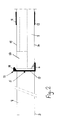
- the adjoining plate-shaped element 3 is provided with a recess in the shape of a cross groove 24 near the end edge, which, at the location of the opening 20, merges into a longitudinal groove 25, to which a cross groove 27 is contiguous, terminating in the longitudinal edge at the location of the trimming joist 5, all this in a manner such that a cross groove 28 provided in the end edge of the trimmed plate-shaped element 7 is situated in alignment with the cross groove 27 as also shown in Fig. 2.
- a suitable passage 29 in the body part of the longitudinal girder 8 a pipe channel extending all around the opening 20 can be formed.
- a trimmed plate-shaped element 7 along which a longitudinal girder 8 extends is provided over its length with a recess 22 for receiving the longitudinal girder 8, which, hence, comes to lie with its top surface in the upper plane of the floor 2.
- the required space can be designed such that the provision of a recess in a plate-shaped element can be dispensed with.
- this recess can also be enlarged, thus creating the possibility to obtain an opening 20 having a width smaller than the total of the widths of a number of trimmed plate-shaped elements 7, as will be further elucidated with reference to Fig. 4.
- the length of the trimming joist 5 is then geared to the desired width of the opening 20, which is larger than the total of the widths of the two trimmed plate-shaped elements 7 but smaller than the total of the widths of the three trimmed plate-shaped elements 7.
- the trimmer accessory 21 can be placed in the manner proposed by the invention with its longitudinal girders 8 along the edges of the trimmed plate-shaped elements 7.
- the thus created space 30 between a longitudinal girder 8 and an adjoining plate-shaped element 3 can then be filled by, for instance, pouring concrete or placing a prefab element.
- a recess can be provided in the other trimmed plate-shaped element 7 placed in the other extremity of the trimming joist 5. This, in turn, gives more freedom in positioning the opening 20 in a floor built up from standard elements according to a fixed pattern.
- the trimmer accessory 21 can be placed at the location provided to that end with its bearing ends 9 on the supporting wall and further be horizontally supported or shored-up, whereupon the trimmed plate-shaped element 7 can be laid on the one side on the supporting wall and on the other side on the trimming joist 5. Due to the stop element 11 contacting against the top surface of the trimmed plate-shaped element 7, a stable construction is obtained, whereupon the support or shore can be removed.
- Providing a support or shore can be dispensed with when at least one of the longitudinal girders 8 is provided at its supporting end 10 with a plate-shaped locking element 12, represented in Fig.
- trimmer accessory 21 can then be slid onto the trimmed plate-shaped element 7 until the front edge of that trimmed plate-shaped element 7 rests on the leg 6 of the trimming joist 5.
- the trimmed plate-shaped element 7 with slid-on trimmer accessory 21 can be taken up in the manner of a non-trimmed plate-shaped element and be laid on the provided place on the supporting walls, whereupon the trimmer construction 1 can be finished without a shore or support being necessary.
- providing an opening adjoining a supporting wall and at a distance from a sidewall is represented.
- the longitudinal girder can be dispensed with and be replaced with a suspending or bearing provision on the trimming joist, with which it bears on or against this sidewall.
- the opening is not situated contiguous to the wall, this can be realized by designing the construction doubly, in a mirror symmetrical manner.
- Fig. 1 or Fig. 4 could be viewed as a cross section halfway the opening provided in the floor at a distance from the supporting wall.
- one of the longitudinal girders can be dispensed with through replacement by bearing or suspending provisions on the, in that case, two trimming joists.
- both the stop element and the locking element can be designed differently, for instance L-shaped or Z-shaped, while then, the longitudinal girder could consist of an L-profile, whose horizontal leg could extend below the adjoining plate-shaped part.
- several stop elements can be provided on a longitudinal girder, which, if desired, could form a long, one-part continuous covering plate.
- What can be considered, further, is to connect the generally H-shaped trimmer accessory between the bearing ends forming the extremities by a further profile, so that the opening in the floor would be surrounded entirely by smooth profiles.
- it could be considered to replace two oppositely located stop elements with a plate-shaped strip extending over the full width of the trimmer accessory.
Landscapes
- Engineering & Computer Science (AREA)
- Architecture (AREA)
- Physics & Mathematics (AREA)
- Electromagnetism (AREA)
- Civil Engineering (AREA)
- Structural Engineering (AREA)
- Floor Finish (AREA)
- Warehouses Or Storage Devices (AREA)
- Joining Of Building Structures In Genera (AREA)
- Finishing Walls (AREA)
Applications Claiming Priority (2)
| Application Number | Priority Date | Filing Date | Title |
|---|---|---|---|
| NL1021039A NL1021039C2 (nl) | 2002-07-09 | 2002-07-09 | Raveelconstructie voor een vloer samengesteld uit plaatvormige elementen alsmede een daarbij te gebruiken raveelhulpstuk. |
| NL1021039 | 2002-07-09 |
Publications (2)
| Publication Number | Publication Date |
|---|---|
| EP1380703A1 true EP1380703A1 (fr) | 2004-01-14 |
| EP1380703B1 EP1380703B1 (fr) | 2008-08-06 |
Family
ID=27800745
Family Applications (1)
| Application Number | Title | Priority Date | Filing Date |
|---|---|---|---|
| EP03077154A Expired - Lifetime EP1380703B1 (fr) | 2002-07-09 | 2003-07-08 | Enchevetrure pour plancher compose de panneaux et piece accesoire utilisee a cet effet |
Country Status (7)
| Country | Link |
|---|---|
| EP (1) | EP1380703B1 (fr) |
| AT (1) | ATE403787T1 (fr) |
| DE (1) | DE60322633D1 (fr) |
| DK (1) | DK1380703T3 (fr) |
| ES (1) | ES2311669T3 (fr) |
| NL (1) | NL1021039C2 (fr) |
| NO (1) | NO332237B1 (fr) |
Cited By (2)
| Publication number | Priority date | Publication date | Assignee | Title |
|---|---|---|---|---|
| NL1027296C2 (nl) * | 2004-10-19 | 2006-04-20 | Betonson B V | Vloerplaat voorzien van een beloopbaar spiegelvlak. |
| FI20246143A1 (en) * | 2024-06-10 | 2025-12-11 | Peikko Group Oy | Hollow core slab bracket |
Families Citing this family (1)
| Publication number | Priority date | Publication date | Assignee | Title |
|---|---|---|---|---|
| CN113530049B (zh) * | 2021-07-26 | 2022-10-04 | 广东华坤建设集团有限公司 | 一种空心楼板结构 |
Citations (4)
| Publication number | Priority date | Publication date | Assignee | Title |
|---|---|---|---|---|
| GB410982A (en) * | 1932-06-21 | 1934-05-31 | Kristian Hindhede | Improvements in reinforced-concrete beams and floors, roofs, walls and like structures formed thereof |
| DE1961036A1 (de) * | 1968-12-05 | 1970-06-18 | Ellner Karl Erik Olof Tage | Wechsel fuer Dach- oder Deckenelemente |
| US3613327A (en) * | 1969-03-27 | 1971-10-19 | Herbert Lynwood Hall | Structural system for walls or ceilings or decks |
| US5660020A (en) * | 1994-08-26 | 1997-08-26 | Engineering Certifiers Limited | Method of construction using pre-cast floor units |
-
2002
- 2002-07-09 NL NL1021039A patent/NL1021039C2/nl not_active IP Right Cessation
-
2003
- 2003-07-08 DE DE60322633T patent/DE60322633D1/de not_active Expired - Lifetime
- 2003-07-08 EP EP03077154A patent/EP1380703B1/fr not_active Expired - Lifetime
- 2003-07-08 ES ES03077154T patent/ES2311669T3/es not_active Expired - Lifetime
- 2003-07-08 AT AT03077154T patent/ATE403787T1/de active
- 2003-07-08 DK DK03077154T patent/DK1380703T3/da active
- 2003-07-08 NO NO20033124A patent/NO332237B1/no not_active IP Right Cessation
Patent Citations (4)
| Publication number | Priority date | Publication date | Assignee | Title |
|---|---|---|---|---|
| GB410982A (en) * | 1932-06-21 | 1934-05-31 | Kristian Hindhede | Improvements in reinforced-concrete beams and floors, roofs, walls and like structures formed thereof |
| DE1961036A1 (de) * | 1968-12-05 | 1970-06-18 | Ellner Karl Erik Olof Tage | Wechsel fuer Dach- oder Deckenelemente |
| US3613327A (en) * | 1969-03-27 | 1971-10-19 | Herbert Lynwood Hall | Structural system for walls or ceilings or decks |
| US5660020A (en) * | 1994-08-26 | 1997-08-26 | Engineering Certifiers Limited | Method of construction using pre-cast floor units |
Cited By (3)
| Publication number | Priority date | Publication date | Assignee | Title |
|---|---|---|---|---|
| NL1027296C2 (nl) * | 2004-10-19 | 2006-04-20 | Betonson B V | Vloerplaat voorzien van een beloopbaar spiegelvlak. |
| EP1655120A1 (fr) * | 2004-10-19 | 2006-05-10 | Betonson B.V. | Panneau de plancher avec une surface de miroir circulable |
| FI20246143A1 (en) * | 2024-06-10 | 2025-12-11 | Peikko Group Oy | Hollow core slab bracket |
Also Published As
| Publication number | Publication date |
|---|---|
| ATE403787T1 (de) | 2008-08-15 |
| DK1380703T3 (da) | 2008-12-01 |
| NL1021039C2 (nl) | 2004-01-13 |
| DE60322633D1 (de) | 2008-09-18 |
| EP1380703B1 (fr) | 2008-08-06 |
| NO332237B1 (no) | 2012-08-06 |
| NO20033124D0 (no) | 2003-07-08 |
| ES2311669T3 (es) | 2009-02-16 |
Similar Documents
| Publication | Publication Date | Title |
|---|---|---|
| JP2019526004A (ja) | プレキャストコンクリート型枠、床システム、および建築方法 | |
| US20100170194A1 (en) | Girders for reinforcing concrete and method for connecting them to pillars in order to provide continuity from bay to bay | |
| US6668512B2 (en) | Lightweight building component | |
| JP2001512198A (ja) | 建築構造の建設に使用する建築パネル | |
| US20040231276A1 (en) | Structural formwork member | |
| RU2178042C2 (ru) | Строительный каркас композиционной структуры | |
| KR102080594B1 (ko) | 커플거더 | |
| EP2076637B1 (fr) | Raidissement de dalles de plancher intermédiaire porteuses dans des bâtiments | |
| EP1380703B1 (fr) | Enchevetrure pour plancher compose de panneaux et piece accesoire utilisee a cet effet | |
| EP2241692A2 (fr) | Module de maison, maison comprenant des modules et procédé pour construire une maison | |
| JPH08239934A (ja) | 床スラブ上面段差構造 | |
| EP0987377A2 (fr) | Coffrage perdu pour planchers | |
| KR200153041Y1 (ko) | 하프pc 콘크리트 슬라브판넬 | |
| KR102832174B1 (ko) | 리브 보강형 데크 거푸집 | |
| KR102755429B1 (ko) | 복합 리브형 데크 거푸집 | |
| JP2725572B2 (ja) | 鉄筋コンクリート造での小梁施工方法 | |
| KR101708274B1 (ko) | 중공슬래브용 일체형 중공부재 및 이를 이용한 중공 슬림 플로어와 중공 무량판 구조 | |
| JP3028297B2 (ja) | ハーフプレキャスト床版及びこれを用いた床構造 | |
| WO2013028072A1 (fr) | Dalle de plancher pour fabriquer un plancher | |
| JP2003193484A (ja) | Pc基礎梁部材ならびにこれを使用する布基礎あるいはべた基礎の構築方法 | |
| JP2696196B2 (ja) | コンクリート造建築物の構築方法 | |
| JPH09184227A (ja) | 長尺フロアパネル及びその長尺フロアパネルを用いた複合床材 | |
| JPS6134468Y2 (fr) | ||
| JP2022177672A (ja) | 合成小梁 | |
| KR20230105488A (ko) | 제조·조립분리형 비탈형 보 거푸집의 시공방법 및 이에 적용되는 공장 제작형 비탈형 보 거푸집 |
Legal Events
| Date | Code | Title | Description |
|---|---|---|---|
| PUAI | Public reference made under article 153(3) epc to a published international application that has entered the european phase |
Free format text: ORIGINAL CODE: 0009012 |
|
| AK | Designated contracting states |
Kind code of ref document: A1 Designated state(s): AT BE BG CH CY CZ DE DK EE ES FI FR GB GR HU IE IT LI LU MC NL PT RO SE SI SK TR |
|
| AX | Request for extension of the european patent |
Extension state: AL LT LV MK |
|
| 17P | Request for examination filed |
Effective date: 20040714 |
|
| AKX | Designation fees paid |
Designated state(s): AT BE BG CH CY CZ DE DK EE ES FI FR GB GR HU IE IT LI LU MC NL PT RO SE SI SK TR |
|
| 17Q | First examination report despatched |
Effective date: 20051202 |
|
| GRAP | Despatch of communication of intention to grant a patent |
Free format text: ORIGINAL CODE: EPIDOSNIGR1 |
|
| GRAS | Grant fee paid |
Free format text: ORIGINAL CODE: EPIDOSNIGR3 |
|
| GRAA | (expected) grant |
Free format text: ORIGINAL CODE: 0009210 |
|
| AK | Designated contracting states |
Kind code of ref document: B1 Designated state(s): AT BE BG CH CY CZ DE DK EE ES FI FR GB GR HU IE IT LI LU MC NL PT RO SE SI SK TR |
|
| REG | Reference to a national code |
Ref country code: GB Ref legal event code: FG4D |
|
| REG | Reference to a national code |
Ref country code: CH Ref legal event code: EP |
|
| REG | Reference to a national code |
Ref country code: IE Ref legal event code: FG4D |
|
| REF | Corresponds to: |
Ref document number: 60322633 Country of ref document: DE Date of ref document: 20080918 Kind code of ref document: P |
|
| REG | Reference to a national code |
Ref country code: SE Ref legal event code: TRGR |
|
| REG | Reference to a national code |
Ref country code: DK Ref legal event code: T3 |
|
| REG | Reference to a national code |
Ref country code: ES Ref legal event code: FG2A Ref document number: 2311669 Country of ref document: ES Kind code of ref document: T3 |
|
| PG25 | Lapsed in a contracting state [announced via postgrant information from national office to epo] |
Ref country code: SI Free format text: LAPSE BECAUSE OF FAILURE TO SUBMIT A TRANSLATION OF THE DESCRIPTION OR TO PAY THE FEE WITHIN THE PRESCRIBED TIME-LIMIT Effective date: 20080806 |
|
| PG25 | Lapsed in a contracting state [announced via postgrant information from national office to epo] |
Ref country code: BG Free format text: LAPSE BECAUSE OF FAILURE TO SUBMIT A TRANSLATION OF THE DESCRIPTION OR TO PAY THE FEE WITHIN THE PRESCRIBED TIME-LIMIT Effective date: 20081106 |
|
| PG25 | Lapsed in a contracting state [announced via postgrant information from national office to epo] |
Ref country code: SK Free format text: LAPSE BECAUSE OF FAILURE TO SUBMIT A TRANSLATION OF THE DESCRIPTION OR TO PAY THE FEE WITHIN THE PRESCRIBED TIME-LIMIT Effective date: 20080806 Ref country code: RO Free format text: LAPSE BECAUSE OF FAILURE TO SUBMIT A TRANSLATION OF THE DESCRIPTION OR TO PAY THE FEE WITHIN THE PRESCRIBED TIME-LIMIT Effective date: 20080806 Ref country code: PT Free format text: LAPSE BECAUSE OF FAILURE TO SUBMIT A TRANSLATION OF THE DESCRIPTION OR TO PAY THE FEE WITHIN THE PRESCRIBED TIME-LIMIT Effective date: 20090106 Ref country code: CZ Free format text: LAPSE BECAUSE OF FAILURE TO SUBMIT A TRANSLATION OF THE DESCRIPTION OR TO PAY THE FEE WITHIN THE PRESCRIBED TIME-LIMIT Effective date: 20080806 |
|
| PLBE | No opposition filed within time limit |
Free format text: ORIGINAL CODE: 0009261 |
|
| STAA | Information on the status of an ep patent application or granted ep patent |
Free format text: STATUS: NO OPPOSITION FILED WITHIN TIME LIMIT |
|
| 26N | No opposition filed |
Effective date: 20090507 |
|
| PG25 | Lapsed in a contracting state [announced via postgrant information from national office to epo] |
Ref country code: EE Free format text: LAPSE BECAUSE OF FAILURE TO SUBMIT A TRANSLATION OF THE DESCRIPTION OR TO PAY THE FEE WITHIN THE PRESCRIBED TIME-LIMIT Effective date: 20080806 |
|
| PG25 | Lapsed in a contracting state [announced via postgrant information from national office to epo] |
Ref country code: MC Free format text: LAPSE BECAUSE OF NON-PAYMENT OF DUE FEES Effective date: 20090731 |
|
| REG | Reference to a national code |
Ref country code: CH Ref legal event code: PL |
|
| PG25 | Lapsed in a contracting state [announced via postgrant information from national office to epo] |
Ref country code: LI Free format text: LAPSE BECAUSE OF NON-PAYMENT OF DUE FEES Effective date: 20090731 Ref country code: CH Free format text: LAPSE BECAUSE OF NON-PAYMENT OF DUE FEES Effective date: 20090731 |
|
| PG25 | Lapsed in a contracting state [announced via postgrant information from national office to epo] |
Ref country code: GR Free format text: LAPSE BECAUSE OF FAILURE TO SUBMIT A TRANSLATION OF THE DESCRIPTION OR TO PAY THE FEE WITHIN THE PRESCRIBED TIME-LIMIT Effective date: 20081107 |
|
| PG25 | Lapsed in a contracting state [announced via postgrant information from national office to epo] |
Ref country code: LU Free format text: LAPSE BECAUSE OF NON-PAYMENT OF DUE FEES Effective date: 20090708 |
|
| PG25 | Lapsed in a contracting state [announced via postgrant information from national office to epo] |
Ref country code: HU Free format text: LAPSE BECAUSE OF FAILURE TO SUBMIT A TRANSLATION OF THE DESCRIPTION OR TO PAY THE FEE WITHIN THE PRESCRIBED TIME-LIMIT Effective date: 20090207 |
|
| PG25 | Lapsed in a contracting state [announced via postgrant information from national office to epo] |
Ref country code: TR Free format text: LAPSE BECAUSE OF FAILURE TO SUBMIT A TRANSLATION OF THE DESCRIPTION OR TO PAY THE FEE WITHIN THE PRESCRIBED TIME-LIMIT Effective date: 20080806 |
|
| PG25 | Lapsed in a contracting state [announced via postgrant information from national office to epo] |
Ref country code: CY Free format text: LAPSE BECAUSE OF FAILURE TO SUBMIT A TRANSLATION OF THE DESCRIPTION OR TO PAY THE FEE WITHIN THE PRESCRIBED TIME-LIMIT Effective date: 20080806 |
|
| REG | Reference to a national code |
Ref country code: FR Ref legal event code: PLFP Year of fee payment: 13 |
|
| REG | Reference to a national code |
Ref country code: FR Ref legal event code: PLFP Year of fee payment: 14 |
|
| REG | Reference to a national code |
Ref country code: FR Ref legal event code: PLFP Year of fee payment: 15 |
|
| REG | Reference to a national code |
Ref country code: FR Ref legal event code: PLFP Year of fee payment: 16 |
|
| PGFP | Annual fee paid to national office [announced via postgrant information from national office to epo] |
Ref country code: ES Payment date: 20200922 Year of fee payment: 18 |
|
| PGFP | Annual fee paid to national office [announced via postgrant information from national office to epo] |
Ref country code: NL Payment date: 20210622 Year of fee payment: 19 |
|
| PGFP | Annual fee paid to national office [announced via postgrant information from national office to epo] |
Ref country code: FI Payment date: 20210722 Year of fee payment: 19 Ref country code: AT Payment date: 20210722 Year of fee payment: 19 Ref country code: FR Payment date: 20210727 Year of fee payment: 19 Ref country code: IT Payment date: 20210727 Year of fee payment: 19 Ref country code: IE Payment date: 20210723 Year of fee payment: 19 |
|
| PGFP | Annual fee paid to national office [announced via postgrant information from national office to epo] |
Ref country code: DK Payment date: 20210723 Year of fee payment: 19 Ref country code: GB Payment date: 20210721 Year of fee payment: 19 Ref country code: SE Payment date: 20210721 Year of fee payment: 19 Ref country code: DE Payment date: 20210721 Year of fee payment: 19 Ref country code: BE Payment date: 20210721 Year of fee payment: 19 |
|
| REG | Reference to a national code |
Ref country code: ES Ref legal event code: FD2A Effective date: 20220829 |
|
| PG25 | Lapsed in a contracting state [announced via postgrant information from national office to epo] |
Ref country code: ES Free format text: LAPSE BECAUSE OF NON-PAYMENT OF DUE FEES Effective date: 20210709 |
|
| REG | Reference to a national code |
Ref country code: DE Ref legal event code: R119 Ref document number: 60322633 Country of ref document: DE |
|
| REG | Reference to a national code |
Ref country code: DK Ref legal event code: EBP Effective date: 20220731 |
|
| REG | Reference to a national code |
Ref country code: SE Ref legal event code: EUG |
|
| REG | Reference to a national code |
Ref country code: NL Ref legal event code: MM Effective date: 20210801 |
|
| REG | Reference to a national code |
Ref country code: AT Ref legal event code: MM01 Ref document number: 403787 Country of ref document: AT Kind code of ref document: T Effective date: 20220708 |
|
| GBPC | Gb: european patent ceased through non-payment of renewal fee |
Effective date: 20220708 |
|
| REG | Reference to a national code |
Ref country code: BE Ref legal event code: MM Effective date: 20220731 |
|
| PG25 | Lapsed in a contracting state [announced via postgrant information from national office to epo] |
Ref country code: SE Free format text: LAPSE BECAUSE OF NON-PAYMENT OF DUE FEES Effective date: 20220709 Ref country code: FR Free format text: LAPSE BECAUSE OF NON-PAYMENT OF DUE FEES Effective date: 20220731 Ref country code: FI Free format text: LAPSE BECAUSE OF NON-PAYMENT OF DUE FEES Effective date: 20220708 Ref country code: AT Free format text: LAPSE BECAUSE OF NON-PAYMENT OF DUE FEES Effective date: 20220708 |
|
| PG25 | Lapsed in a contracting state [announced via postgrant information from national office to epo] |
Ref country code: GB Free format text: LAPSE BECAUSE OF NON-PAYMENT OF DUE FEES Effective date: 20220708 Ref country code: DE Free format text: LAPSE BECAUSE OF NON-PAYMENT OF DUE FEES Effective date: 20230201 Ref country code: BE Free format text: LAPSE BECAUSE OF NON-PAYMENT OF DUE FEES Effective date: 20220731 |
|
| PG25 | Lapsed in a contracting state [announced via postgrant information from national office to epo] |
Ref country code: NL Free format text: LAPSE BECAUSE OF NON-PAYMENT OF DUE FEES Effective date: 20210801 |
|
| PG25 | Lapsed in a contracting state [announced via postgrant information from national office to epo] |
Ref country code: IT Free format text: LAPSE BECAUSE OF NON-PAYMENT OF DUE FEES Effective date: 20220708 Ref country code: IE Free format text: LAPSE BECAUSE OF NON-PAYMENT OF DUE FEES Effective date: 20220708 Ref country code: DK Free format text: LAPSE BECAUSE OF NON-PAYMENT OF DUE FEES Effective date: 20220731 |