EP1380716A2 - Verschluss mit zwei Drehfallen, insbesondere für Fahrzeuge - Google Patents
Verschluss mit zwei Drehfallen, insbesondere für Fahrzeuge Download PDFInfo
- Publication number
- EP1380716A2 EP1380716A2 EP03014139A EP03014139A EP1380716A2 EP 1380716 A2 EP1380716 A2 EP 1380716A2 EP 03014139 A EP03014139 A EP 03014139A EP 03014139 A EP03014139 A EP 03014139A EP 1380716 A2 EP1380716 A2 EP 1380716A2
- Authority
- EP
- European Patent Office
- Prior art keywords
- shaft
- closure according
- closure
- webs
- axial
- Prior art date
- Legal status (The legal status is an assumption and is not a legal conclusion. Google has not performed a legal analysis and makes no representation as to the accuracy of the status listed.)
- Granted
Links
- 239000000463 material Substances 0.000 claims abstract description 8
- 238000005452 bending Methods 0.000 claims abstract description 5
- 229920003023 plastic Polymers 0.000 claims description 5
- 229920002457 flexible plastic Polymers 0.000 claims 1
- 239000000872 buffer Substances 0.000 description 3
- 230000000903 blocking effect Effects 0.000 description 2
- 229910001229 Pot metal Inorganic materials 0.000 description 1
- 206010053648 Vascular occlusion Diseases 0.000 description 1
- 230000001419 dependent effect Effects 0.000 description 1
- 230000000694 effects Effects 0.000 description 1
- 239000013536 elastomeric material Substances 0.000 description 1
- 230000012447 hatching Effects 0.000 description 1
- 238000001746 injection moulding Methods 0.000 description 1
- 230000007257 malfunction Effects 0.000 description 1
- 238000004519 manufacturing process Methods 0.000 description 1
- 239000002184 metal Substances 0.000 description 1
- 229910052751 metal Inorganic materials 0.000 description 1
- 230000000284 resting effect Effects 0.000 description 1
- 230000003319 supportive effect Effects 0.000 description 1
Images


Classifications
-
- E—FIXED CONSTRUCTIONS
- E05—LOCKS; KEYS; WINDOW OR DOOR FITTINGS; SAFES
- E05C—BOLTS OR FASTENING DEVICES FOR WINGS, SPECIALLY FOR DOORS OR WINDOWS
- E05C3/00—Fastening devices with bolts moving pivotally or rotatively
- E05C3/12—Fastening devices with bolts moving pivotally or rotatively with latching action
- E05C3/16—Fastening devices with bolts moving pivotally or rotatively with latching action with operating handle or equivalent member moving otherwise than rigidly with the latch
- E05C3/22—Fastening devices with bolts moving pivotally or rotatively with latching action with operating handle or equivalent member moving otherwise than rigidly with the latch the bolt being spring controlled
- E05C3/24—Fastening devices with bolts moving pivotally or rotatively with latching action with operating handle or equivalent member moving otherwise than rigidly with the latch the bolt being spring controlled in the form of a bifurcated member
-
- E—FIXED CONSTRUCTIONS
- E05—LOCKS; KEYS; WINDOW OR DOOR FITTINGS; SAFES
- E05B—LOCKS; ACCESSORIES THEREFOR; HANDCUFFS
- E05B77/00—Vehicle locks characterised by special functions or purposes
- E05B77/36—Noise prevention; Anti-rattling means
- E05B77/38—Cushion elements, elastic guiding elements or holding elements, e.g. for cushioning or damping the impact of the bolt against the striker during closing of the wing
-
- E—FIXED CONSTRUCTIONS
- E05—LOCKS; KEYS; WINDOW OR DOOR FITTINGS; SAFES
- E05B—LOCKS; ACCESSORIES THEREFOR; HANDCUFFS
- E05B77/00—Vehicle locks characterised by special functions or purposes
- E05B77/36—Noise prevention; Anti-rattling means
- E05B77/40—Lock elements covered by silencing layers, e.g. coatings
-
- E—FIXED CONSTRUCTIONS
- E05—LOCKS; KEYS; WINDOW OR DOOR FITTINGS; SAFES
- E05B—LOCKS; ACCESSORIES THEREFOR; HANDCUFFS
- E05B63/00—Locks or fastenings with special structural characteristics
- E05B63/14—Arrangement of several locks or locks with several bolts, e.g. arranged one behind the other
-
- E—FIXED CONSTRUCTIONS
- E05—LOCKS; KEYS; WINDOW OR DOOR FITTINGS; SAFES
- E05B—LOCKS; ACCESSORIES THEREFOR; HANDCUFFS
- E05B85/00—Details of vehicle locks not provided for in groups E05B77/00 - E05B83/00
- E05B85/20—Bolts or detents
- E05B85/24—Bolts rotating about an axis
- E05B85/26—Cooperation between bolts and detents
-
- Y—GENERAL TAGGING OF NEW TECHNOLOGICAL DEVELOPMENTS; GENERAL TAGGING OF CROSS-SECTIONAL TECHNOLOGIES SPANNING OVER SEVERAL SECTIONS OF THE IPC; TECHNICAL SUBJECTS COVERED BY FORMER USPC CROSS-REFERENCE ART COLLECTIONS [XRACs] AND DIGESTS
- Y10—TECHNICAL SUBJECTS COVERED BY FORMER USPC
- Y10T—TECHNICAL SUBJECTS COVERED BY FORMER US CLASSIFICATION
- Y10T292/00—Closure fasteners
- Y10T292/08—Bolts
- Y10T292/0801—Multiple
- Y10T292/081—Swinging and hooked end
-
- Y—GENERAL TAGGING OF NEW TECHNOLOGICAL DEVELOPMENTS; GENERAL TAGGING OF CROSS-SECTIONAL TECHNOLOGIES SPANNING OVER SEVERAL SECTIONS OF THE IPC; TECHNICAL SUBJECTS COVERED BY FORMER USPC CROSS-REFERENCE ART COLLECTIONS [XRACs] AND DIGESTS
- Y10—TECHNICAL SUBJECTS COVERED BY FORMER USPC
- Y10T—TECHNICAL SUBJECTS COVERED BY FORMER US CLASSIFICATION
- Y10T292/00—Closure fasteners
- Y10T292/08—Bolts
- Y10T292/0801—Multiple
- Y10T292/0825—Hooked end
- Y10T292/0826—Operating means
-
- Y—GENERAL TAGGING OF NEW TECHNOLOGICAL DEVELOPMENTS; GENERAL TAGGING OF CROSS-SECTIONAL TECHNOLOGIES SPANNING OVER SEVERAL SECTIONS OF THE IPC; TECHNICAL SUBJECTS COVERED BY FORMER USPC CROSS-REFERENCE ART COLLECTIONS [XRACs] AND DIGESTS
- Y10—TECHNICAL SUBJECTS COVERED BY FORMER USPC
- Y10T—TECHNICAL SUBJECTS COVERED BY FORMER US CLASSIFICATION
- Y10T292/00—Closure fasteners
- Y10T292/08—Bolts
- Y10T292/0801—Multiple
- Y10T292/0825—Hooked end
- Y10T292/0826—Operating means
- Y10T292/083—Flexible
-
- Y—GENERAL TAGGING OF NEW TECHNOLOGICAL DEVELOPMENTS; GENERAL TAGGING OF CROSS-SECTIONAL TECHNOLOGIES SPANNING OVER SEVERAL SECTIONS OF THE IPC; TECHNICAL SUBJECTS COVERED BY FORMER USPC CROSS-REFERENCE ART COLLECTIONS [XRACs] AND DIGESTS
- Y10—TECHNICAL SUBJECTS COVERED BY FORMER USPC
- Y10T—TECHNICAL SUBJECTS COVERED BY FORMER US CLASSIFICATION
- Y10T292/00—Closure fasteners
- Y10T292/08—Bolts
- Y10T292/0801—Multiple
- Y10T292/0848—Swinging
- Y10T292/0849—Operating means
-
- Y—GENERAL TAGGING OF NEW TECHNOLOGICAL DEVELOPMENTS; GENERAL TAGGING OF CROSS-SECTIONAL TECHNOLOGIES SPANNING OVER SEVERAL SECTIONS OF THE IPC; TECHNICAL SUBJECTS COVERED BY FORMER USPC CROSS-REFERENCE ART COLLECTIONS [XRACs] AND DIGESTS
- Y10—TECHNICAL SUBJECTS COVERED BY FORMER USPC
- Y10T—TECHNICAL SUBJECTS COVERED BY FORMER US CLASSIFICATION
- Y10T292/00—Closure fasteners
- Y10T292/08—Bolts
- Y10T292/0862—Swinging and hooked end, multiple head
Definitions
- the invention relates to a closure in the preamble of claim 1 mentioned type.
- the two rotary latches act in their closed position with two Strikers together. Your locking position is secured by two locking elements, which are integrally formed with a shaft connecting them and with the shaft can be rotated synchronously.
- the invention has for its object a closure in the preamble of Claim 1 type to develop, which is characterized by great operational reliability distinguished. This is according to the invention by those mentioned in claim 1 Measures achieved, which have the following special importance.
- the flexibility of the shaft or at least a section of it allows one Compensation for tolerances that may arise in later use Depending on the influence of heat can increase considerably. Yet is the synchronization of the two locking levers due to the good torsional rigidity of the guaranteed wave according to the invention.
- the one-piece according to the invention of Shaft and the two locking levers creates a "combination" that the Permits use of plastic. This affects the weight and price of the Cheap closure.
- the flexibility of the shaft is also very advantageous for the assembly of the one-piece combination according to the invention on their bearings.
- This particular combination according to the invention can be carried out on the shaft alternate order of rigid and bendable axial pieces.
- a One way to achieve this is to make these two axial pieces out of two to form different materials, namely one bend-friendly material on the one hand and a more dimensionally stable material on the other. Both materials are made of plastic, from which the injection molding Combination arises.
- the closure according to the invention includes two rotary latches 11, 12 which are connected to two Bearing blocks 31, 32 are stored at 13, 14.
- the bearing blocks 31, 32 are in one piece formed with a carrier 30. Because both traps are the same trained, it suffices their structure and mode of operation on the one hand 4 and 5 to explain in more detail.
- the closure serves, as shown in FIG. 4, around a movable part 15, which in the present case consists of a pivotable flap, opposite a resting part 35.
- a movable part 15 which in the present case consists of a pivotable flap, opposite a resting part 35.
- Rotary traps 11, 12 bearing supports 30 are attached to the stationary part 35, to which the 1 serve fastening ends 33, 34 which can be seen in FIG.
- At the pivotable flap 15 sit two brackets, which are provided with strikers 10 and are assigned to the two rotary latches 11, 12. 4 and 5 is only one Shackle 16 shown with its striker 10.
- the rotary latches 11, 12, as shown in FIGS. 4 and 5, have a cutout 17, in which the striker 10 is received when the catch 11 in their pivot position identified by the auxiliary line 11.1, which as "Closed position" is to be designated. Then the pivotable flap 15 is on hers Housing 35 set.
- This blocking position 11.1 is by a first blocking element 31 secured, which engages behind a radial shoulder 18.
- a second locking member 22 is on an analog radial shoulder 19 provided on the latch 12 there supported.
- the locking members 21, 22 sit at the ends of a common connecting them Shaft 20, with which they are integrally formed from plastic and forms with this a combination.
- This shaft 20 has dashed lines in FIG. 1 end bearing bolts 23, 24 which in corresponding, facing each other Intervene blind holes.
- the blind holes belong to two repositories 36, 37 which are integrally formed with the carrier 30.
- the axis of rotation 25 of the shaft 20 and its locking members 21, 22 is indicated by dash-dotted lines in Fig. 1 and in Figs. 4 and 5 marked. Both the rotary latches 11, 12 and the one-piece combination 40 are under the action of restoring forces, in the present case of a common, two-leg return spring 38 and 39 are generated.
- the shaft 20 has a special profile, which they are in the direction of rotation 43, according to FIGS. 2 and 3, torsionally rigid, but in the axial direction 25 makes it flexible.
- the rigid axial pieces 26 consist of Discs with a circular outline 29, which are lamellar at an axial distance from one another are positioned, the distance range between them by two diametrical Bridges 44 or 45 is bridged.
- Successive webs 44, 45 stand perpendicular to each other.
- the webs 44, 45 act like "film hinges" between the successive slices 26.
- the one web 44 e.g.
- the degree of flexibility is due to the axial web length between the successive discs 26 and the radial web thickness determined.
- the Torsional stiffness results from the continuous web structure and the relatively low web height between the adjacent panes 26.
- the one-piece combination 40 allows quick and easy assembly of the shaft 20 to. For this, their flexibility is used.
- This strong deflection of the shaft is in the middle of the bearing 47 canceled in that a clip 48 overlaps the assembled shaft 20 and is fixed on the carrier at recordings 49. This creates a medium one there Bearing, which prevents the shaft from bending in this area 47.
- Trigger 50 on the combination 40, which is not described in more detail act shown actuating means that are handled manually. Only on that Triggers 50 are exerted torques while on the locking members 21, 22nd no moments need to be transmitted. If the trigger 50 is out of its supportive position in Fig. 4 in its apparent from Fig. 5 release position transferred where the radial shoulder 18 of the rotary latch 11 is released, so the Rotary latch 11 in the already mentioned other position 11.2 due to its restoring force 41 automatically pivoted.
- This rotational position 11.2 is determined by buffer 51 and noise-damped, on which the catch 11 is supported. These buffers 51 are Part of the associated bearing block 31 from the carrier 30. In this rotational position 11.2 the movable part 15, e.g.
- the associated locking member 21 is under the action of the aforementioned Restoring force on the profile of the rotary latch 11.
- This is the outline of the itself Metal existing trap, as indicated by cross hatching in Fig. 5, with a Provided casing 54, which consists of elastomeric material.
- the locking link 21 is ready to move out of its position of FIG. 5 tensioned by the return spring 38 to go into its more relaxed position as shown in FIG. 4.
- the aforementioned closing movement pushes the striker 10 against a nose 55, which limits the rotary latch cutout 17 and rotates the rotary latch 11 against the Effect of their return spring 41 back to the closed position 11.1, where that Locking member 21 automatically moves behind the rotary latch shoulder 18 and the Locked position 11.1 locked.
Landscapes
- Engineering & Computer Science (AREA)
- Mechanical Engineering (AREA)
- Lock And Its Accessories (AREA)
- Pivots And Pivotal Connections (AREA)
- Cooling, Air Intake And Gas Exhaust, And Fuel Tank Arrangements In Propulsion Units (AREA)
- Acyclic And Carbocyclic Compounds In Medicinal Compositions (AREA)
- Medicines Containing Plant Substances (AREA)
Abstract
Description
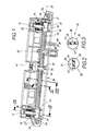
- Fig. 1,
- in perspektivischer Darstellung, eine Baueinheit mit dem erfindungsgemäßen Verschluss, welche an einem stationären Teil neben einer schwenkbeweglichen Klappe angebracht werden soll,
- Fig. 2 + 3,
- in Vergrößerung, Querschnitte durch eine profilierte Welle in der Baueinheit von Fig. 1, längs der dortigen Schnittlinien II - II bzw. III - III,
- Fig. 4,
- in Vergrößerung, einen Querschnitt durch die Baueinheit von Fig. 1, längs der dortigen Schnittlinie IV - IV, nachdem die Baueinheit an dem stationären Teil befestigt ist und mit einem Schließstück zusammenwirkt, welches an einer Klappe sitzt, wobei die Klappe sich in ihrer Schließlage gegenüber dem stationären Teil befindet, und
- Fig. 5,
- in einer der Fig. 4 entsprechenden Darstellung, diesen Bereich, wenn eine Freigabelage des Schließstücks vorliegt.
- 10
- Schließstück
- 11
- erste Drehfalle
- 11.1
- Schließlage von 11
- 11.2
- Freigabelage von 11
- 12
- zweite Drehfalle
- 13
- erste Lagerstelle bei 31 für 11
- 14
- zweite Lagerstelle bei 32 für 12
- 15
- beweglicher Teil, Klappe
- 16
- Bügel für 10
- 17
- Ausschnitt in 11 für 10
- 18
- radiale Schulter von 11 für 21
- 19
- radiale Schulter von 12 für 22
- 20
- Welle
- 21
- erstes Sperrglied
- 22
- zweites Sperrglied
- 23
- erster Lagerbolzen für 36
- 24
- zweiter Lagerbolzen für 37
- 25
- Drehachse von 20 bzw. 40
- 26
- biegesteifes Axialstück von 20, Scheibe
- 27
- erstes biegefähiges Axialstück von 20
- 28
- zweites biegefähiges Axialstück von 20
- 29
- Kreisumriss von 26
- 30
- Träger
- 31
- erster Lagerbock an 30 für 11
- 32
- zweiter Lagerbock an 30 für 12
- 33
- erste Befestigungsstelle an 30
- 34
- zweite Befestigungsstelle an 30
- 35
- ruhender Teil, Gehäuse
- 36
- Endlager für 23 an 30
- 37
- Endlager für 24 an 30
- 38
- erste Rückstellfeder für 11
- 39
- zweite Rückstellfeder für 12
- 40
- einstückige Kombination aus 20 bis 22
- 41
- Pfeil der Rückstellkraft für 11
- 42
- Pfeil der Rückstellkraft für 21
- 43
- Drehrichtung von 20 (Fig. 2, 3)
- 44
- erster Steg von 20 (Fig. 2)
- 45
- zweiter Steg von 20 (Fig. 3)
- 47
- mittlerer Bereich von 20
- 48
- Clip
- 49
- Aufnahme für 48 bei 30
- 50
- Auslöser für 40
- 51
- Puffer für 11 an 30 (Fig. 5)
- 52
- Pfeil der Schwenkbewegung von 15 (Fig. 5)
- 53
- Bewegungsweg von 10 (Fig. 5)
- 54
- Ummantelung von 11 (Fig. 5)
- 55
- Nase an 11 (Fig. 5)
Claims (12)
- Verschluss, insbesondere für Fahrzeuge, zum Verriegeln eines beweglichen Teils (15), wie einer schwenkbaren Klappe, gegenüber einem stationären Teil (35), wie einem Gehäuse,
mit zwei beabstandeten Drehfallen (11, 12), in welche in der Schließlage (11.1) zwei Schließstücke (10) eingreifen,
und mit zwei die beiden Drehfallen (11, 12) in ihrer Schließlage (11.1) haltenden Sperrgliedern (21, 22), die einstückig mit einer sie verbindenden Welle (20) ausgebildet und mit der Welle synchron drehbar (43) sind,
dadurch gekennzeichnet , dass die Welle mindestens abschnittweise zwar in Drehrichtung (43) torsionssteif, aber in Achsrichtung (25) biegsam ausgebildet ist. - Verschluss nach Anspruch 1, dadurch gekennzeichnet, dass die biegsame Welle (20) in abwechselnder Reihenfolge aus biegesteifen (26) und biegefähigen (27, 28) Axialstücken besteht.
- Verschluss nach Anspruch 2, dadurch gekennzeichnet, dass die beiden Axialstücke zwar einstückig aber aus zwei unterschiedlichen Materialien bestehen, nämlich biegefreundlichen Kunststoff einerseits und einem formfesten Kunststoff andererseits.
- Verschluss nach Anspruch 2, dadurch gekennzeichnet, dass die beiden Axialstücke (26, 27, 28) zwar aus einheitlichem Werkstoff, insbesondere Kunststoff, bestehen, aber eine zueinander unterschiedliche Profilierung aufweisen.
- Verschluss nach Anspruch 4, dadurch gekennzeichnet, dass die biegesteifen Axialstücke aus Scheiben (26) bestehen, die durch radiale Stege (44, 45) verbunden sind,
und dass die Stege (44, 45) zwar die biegefähigen Axialstücke (27, 28) bilden, aber torsionssteif sind. - Verschluss nach Anspruch 5, dadurch gekennzeichnet, dass die Scheiben (26) einen Kreisumriss (29) aufweisen und die Stege (44, 45) dazu diametral verlaufen.
- Verschluss nach Anspruch 6, dadurch gekennzeichnet, dass aufeinanderfolgende Stege (44, 45) zueinander drehversetzt sind.
- Verschluss nach Anspruch 7, dadurch gekennzeichnet, dass aufeinanderfolgende Stege (44, 45) zueinander senkrecht positioniert sind.
- Verschluss nach einem der Ansprüche 4 bis 8, dadurch gekennzeichnet, dass die Welle (20) eine Lamellenstruktur aufweist.
- Verschluss nach einem der Ansprüche 1 bis 7, dadurch gekennzeichnet, dass die Kombination (40) aus den beiden Sperrgliedern (21, 22) und der Welle (20) an einem Träger (30) gelagert (36, 37) ist,
dass der Träger (30) zusammen mit den beiden Drehfallen (11, 12) und mit Rückstellfedern (38, 39) eine vormontierbare Baueinheit bildet, welche entweder am stationären (35) oder am beweglichen (15) Teil befestigt (33, 34) ist. - Verschluss nach einem der Ansprüche 1 bis 10, dadurch gekennzeichnet, dass zu ihrer Lagerung die Welle (20) an ihren beiden Enden zwei angeformte Lagerbolzen (23, 24) besitzt
und dass der Träger (30) zwei gegeneinander weisende Sacklöcher aufweist, in welche die Lagerbolzen (23, 24) durch zeitweise Verbiegung der Welle (20) axial einsteckbar sind. - Verschluss nach Anspruch 11, dadurch gekennzeichnet, dass die Welle nach ihrer Montage im Bereich ihres Biegemaximums (47) von einem Clip (48) drehfähig übergriffen wird,
welche am Träger (30) befestigt (49) ist und die Biegefähigkeit der Welle (20) in diesem Bereich (47) aufhebt.
Applications Claiming Priority (2)
| Application Number | Priority Date | Filing Date | Title |
|---|---|---|---|
| DE20210658U | 2002-07-10 | ||
| DE20210658U DE20210658U1 (de) | 2002-07-10 | 2002-07-10 | Verschluss mit zwei Drehfallen, insbesondere für Fahrzeuge |
Publications (3)
| Publication Number | Publication Date |
|---|---|
| EP1380716A2 true EP1380716A2 (de) | 2004-01-14 |
| EP1380716A3 EP1380716A3 (de) | 2006-10-18 |
| EP1380716B1 EP1380716B1 (de) | 2008-08-13 |
Family
ID=7973028
Family Applications (1)
| Application Number | Title | Priority Date | Filing Date |
|---|---|---|---|
| EP03014139A Expired - Lifetime EP1380716B1 (de) | 2002-07-10 | 2003-06-24 | Verschluss mit zwei Drehfallen, insbesondere für Fahrzeuge |
Country Status (4)
| Country | Link |
|---|---|
| US (1) | US6923478B2 (de) |
| EP (1) | EP1380716B1 (de) |
| AT (1) | ATE404766T1 (de) |
| DE (2) | DE20210658U1 (de) |
Families Citing this family (3)
| Publication number | Priority date | Publication date | Assignee | Title |
|---|---|---|---|---|
| DE102005006565B4 (de) * | 2005-02-11 | 2014-07-24 | Johnson Controls Gmbh | Vorrichtung zur Verriegelung und Entriegelung, insbesondere der Lehne eines Sitzes, insbesondere eines Kraftfahrzeugs |
| DE102012023261A1 (de) * | 2012-11-29 | 2014-06-05 | Kiekert Aktiengesellschaft | Kraftfahrzeugschloss |
| CN110114542B (zh) * | 2016-10-21 | 2021-08-10 | 索斯科公司 | 箱子闩锁 |
Family Cites Families (19)
| Publication number | Priority date | Publication date | Assignee | Title |
|---|---|---|---|---|
| US2238480A (en) * | 1940-01-04 | 1941-04-15 | Eastman Kodak Co | Handle latch mechanism |
| DE925027C (de) * | 1952-07-03 | 1955-03-10 | Hermann Dipl-Ing Seidl | Biegsame Welle |
| US3144956A (en) * | 1961-09-21 | 1964-08-18 | Wilmot Castle Co | Control apparatus for doors |
| US3128120A (en) * | 1961-10-24 | 1964-04-07 | Gen Motors Corp | Closure structure for floatable truck body |
| US3134618A (en) * | 1962-04-05 | 1964-05-26 | Fruehauf Corp | Door lock |
| NL6408413A (de) * | 1964-07-23 | 1966-01-24 | ||
| GB1505504A (en) * | 1975-01-16 | 1978-03-30 | Brown Tractors Ltd | Compression spring |
| US3989289A (en) * | 1975-04-09 | 1976-11-02 | Fruehauf Corporation | Door hardware |
| US4115020A (en) * | 1975-10-15 | 1978-09-19 | Overseas Containers Australia Pty Limited | Clamp |
| US4170376A (en) * | 1977-07-11 | 1979-10-09 | Fruehauf Corporation | Dimpled door hardware |
| JPS5736035U (de) * | 1980-08-08 | 1982-02-25 | ||
| US5391360A (en) * | 1986-02-06 | 1995-02-21 | Steris Corporation | Overcenter, cam driven locking mechanism |
| DE8704947U1 (de) * | 1987-04-02 | 1987-05-27 | Hülsbeck & Fürst GmbH & Co KG, 5620 Velbert | Handschuhkasten für Kraftfahrzeuge |
| US4858897A (en) * | 1987-11-16 | 1989-08-22 | Hideki Irifune | Spring |
| US5232073A (en) * | 1988-12-09 | 1993-08-03 | Trw Inc. | Process for damping dynamic load |
| US5168914A (en) * | 1991-02-11 | 1992-12-08 | Hi-Fold Door Corporation | Automatic jamb latch mechanism for overhead bifold door |
| SE9201321L (sv) * | 1992-04-28 | 1993-10-29 | Itab Ind Ab | Universalled |
| GB2316735B (en) * | 1996-08-30 | 2000-01-19 | Reliance Gear Co | Flexible coupling |
| DE19948677B4 (de) * | 1999-10-08 | 2006-11-09 | Audi Ag | Vorrichtung zum Schließen und Öffnen eines verriegelbaren Deckenteils, insbesondere eines Fahrzeugdeckelteils für eine Kofferraumabdeckung |
-
2002
- 2002-07-10 DE DE20210658U patent/DE20210658U1/de not_active Expired - Lifetime
-
2003
- 2003-06-24 DE DE50310304T patent/DE50310304D1/de not_active Expired - Lifetime
- 2003-06-24 EP EP03014139A patent/EP1380716B1/de not_active Expired - Lifetime
- 2003-06-24 AT AT03014139T patent/ATE404766T1/de not_active IP Right Cessation
- 2003-06-28 US US10/609,197 patent/US6923478B2/en not_active Expired - Fee Related
Non-Patent Citations (1)
| Title |
|---|
| None |
Also Published As
| Publication number | Publication date |
|---|---|
| DE50310304D1 (de) | 2008-09-25 |
| ATE404766T1 (de) | 2008-08-15 |
| EP1380716A3 (de) | 2006-10-18 |
| US20040026931A1 (en) | 2004-02-12 |
| DE20210658U1 (de) | 2002-09-19 |
| US6923478B2 (en) | 2005-08-02 |
| EP1380716B1 (de) | 2008-08-13 |
Similar Documents
| Publication | Publication Date | Title |
|---|---|---|
| EP1521893B1 (de) | Verschluss mit zwei riegelstangen, insbesondere für fahrzeuge | |
| DE202007014471U1 (de) | Scharnier für eine Gepäckbox o.dgl. | |
| DE202011109983U1 (de) | Bandantrieb für Zug- und Druckbeanspruchung | |
| DE202005015169U1 (de) | Schwenkschiebetür für Fahrzeuge, insbesondere Fahrgasttür für Fahrzeuge des öffentlichen Personennahverkehrs | |
| EP2167766B1 (de) | Vorrichtung zum betätigen eines verschlusses eines beweglichen teils | |
| EP0711896A2 (de) | Verschlussvorrichtung für Fenster, Türen od. dgl. | |
| DE69723655T2 (de) | Fallsicherungsvorrichtung für vertikal aufrollbare Verschlusseinrichtungen | |
| EP1625269B1 (de) | Treibstangengetriebe | |
| DE102008037956A1 (de) | Klinkensystem mit Kabelbetätigung | |
| DE102008026707A1 (de) | Drehwellenanordnung für ein Tor, insbesondere für ein Rolltor, und ein solches Tor | |
| WO2008034652A1 (de) | Motorischer antrieb | |
| EP1380716A2 (de) | Verschluss mit zwei Drehfallen, insbesondere für Fahrzeuge | |
| DE202013009352U1 (de) | Fenster oder Tür mit einem Beschlag | |
| AT409023B (de) | Drehbetätigungseinrichtung | |
| DE2449180A1 (de) | Selbsthemmungsvorrichtung fuer rotierende wellen | |
| DE3404693A1 (de) | Fahrzeugdach mit schwenkbarem deckel | |
| EP0766794B1 (de) | Kupplung | |
| DE102017103796B4 (de) | Öffnungsmechanismus für einen schmetterlingsdeckel | |
| DE2805931C2 (de) | Vorrichtung zum Lastausgleich des Eigengewichtes eines Deckengliedertores | |
| DE102011000295A1 (de) | Vorrichtung zum automatischen Schließen oder Öffnen einer Schiebetür | |
| DE3741386A1 (de) | Federnde scharnieranordnung fuer schwenktueren, insbesondere fuer automobiltueren | |
| DE19532262A1 (de) | Vorrichtung zur Schließfolgeregelung für zweiflügelige Türen | |
| EP0564398B1 (de) | Vorrichtung zum Oeffnen und Schliessen eines Fensterladens vom Innenraum her | |
| AT502965B1 (de) | Vorrichtung zur regelung der öffnungsfolge von zweiflügeligen schwenktüren | |
| DE102017207359B4 (de) | Bewegungsdämpfungsvorrichtung |
Legal Events
| Date | Code | Title | Description |
|---|---|---|---|
| PUAI | Public reference made under article 153(3) epc to a published international application that has entered the european phase |
Free format text: ORIGINAL CODE: 0009012 |
|
| AK | Designated contracting states |
Kind code of ref document: A2 Designated state(s): AT BE BG CH CY CZ DE DK EE ES FI FR GB GR HU IE IT LI LU MC NL PT RO SE SI SK TR |
|
| AX | Request for extension of the european patent |
Extension state: AL LT LV MK |
|
| PUAL | Search report despatched |
Free format text: ORIGINAL CODE: 0009013 |
|
| AK | Designated contracting states |
Kind code of ref document: A3 Designated state(s): AT BE BG CH CY CZ DE DK EE ES FI FR GB GR HU IE IT LI LU MC NL PT RO SE SI SK TR |
|
| AX | Request for extension of the european patent |
Extension state: AL LT LV MK |
|
| 17P | Request for examination filed |
Effective date: 20070316 |
|
| AKX | Designation fees paid |
Designated state(s): AT BE BG CH CY CZ DE DK EE ES FI FR GB GR HU IE IT LI LU MC NL PT RO SE SI SK TR |
|
| GRAP | Despatch of communication of intention to grant a patent |
Free format text: ORIGINAL CODE: EPIDOSNIGR1 |
|
| GRAS | Grant fee paid |
Free format text: ORIGINAL CODE: EPIDOSNIGR3 |
|
| GRAA | (expected) grant |
Free format text: ORIGINAL CODE: 0009210 |
|
| AK | Designated contracting states |
Kind code of ref document: B1 Designated state(s): AT BE BG CH CY CZ DE DK EE ES FI FR GB GR HU IE IT LI LU MC NL PT RO SE SI SK TR |
|
| REG | Reference to a national code |
Ref country code: GB Ref legal event code: FG4D Free format text: NOT ENGLISH |
|
| REG | Reference to a national code |
Ref country code: CH Ref legal event code: EP |
|
| REG | Reference to a national code |
Ref country code: IE Ref legal event code: FG4D Free format text: LANGUAGE OF EP DOCUMENT: GERMAN |
|
| REF | Corresponds to: |
Ref document number: 50310304 Country of ref document: DE Date of ref document: 20080925 Kind code of ref document: P |
|
| PG25 | Lapsed in a contracting state [announced via postgrant information from national office to epo] |
Ref country code: ES Free format text: LAPSE BECAUSE OF FAILURE TO SUBMIT A TRANSLATION OF THE DESCRIPTION OR TO PAY THE FEE WITHIN THE PRESCRIBED TIME-LIMIT Effective date: 20081124 Ref country code: NL Free format text: LAPSE BECAUSE OF FAILURE TO SUBMIT A TRANSLATION OF THE DESCRIPTION OR TO PAY THE FEE WITHIN THE PRESCRIBED TIME-LIMIT Effective date: 20080813 |
|
| PG25 | Lapsed in a contracting state [announced via postgrant information from national office to epo] |
Ref country code: SI Free format text: LAPSE BECAUSE OF FAILURE TO SUBMIT A TRANSLATION OF THE DESCRIPTION OR TO PAY THE FEE WITHIN THE PRESCRIBED TIME-LIMIT Effective date: 20080813 Ref country code: FI Free format text: LAPSE BECAUSE OF FAILURE TO SUBMIT A TRANSLATION OF THE DESCRIPTION OR TO PAY THE FEE WITHIN THE PRESCRIBED TIME-LIMIT Effective date: 20080813 |
|
| REG | Reference to a national code |
Ref country code: IE Ref legal event code: FD4D |
|
| PG25 | Lapsed in a contracting state [announced via postgrant information from national office to epo] |
Ref country code: DK Free format text: LAPSE BECAUSE OF FAILURE TO SUBMIT A TRANSLATION OF THE DESCRIPTION OR TO PAY THE FEE WITHIN THE PRESCRIBED TIME-LIMIT Effective date: 20080813 Ref country code: BG Free format text: LAPSE BECAUSE OF FAILURE TO SUBMIT A TRANSLATION OF THE DESCRIPTION OR TO PAY THE FEE WITHIN THE PRESCRIBED TIME-LIMIT Effective date: 20081113 Ref country code: IE Free format text: LAPSE BECAUSE OF FAILURE TO SUBMIT A TRANSLATION OF THE DESCRIPTION OR TO PAY THE FEE WITHIN THE PRESCRIBED TIME-LIMIT Effective date: 20080813 |
|
| PG25 | Lapsed in a contracting state [announced via postgrant information from national office to epo] |
Ref country code: PT Free format text: LAPSE BECAUSE OF FAILURE TO SUBMIT A TRANSLATION OF THE DESCRIPTION OR TO PAY THE FEE WITHIN THE PRESCRIBED TIME-LIMIT Effective date: 20090113 Ref country code: RO Free format text: LAPSE BECAUSE OF FAILURE TO SUBMIT A TRANSLATION OF THE DESCRIPTION OR TO PAY THE FEE WITHIN THE PRESCRIBED TIME-LIMIT Effective date: 20080813 Ref country code: SK Free format text: LAPSE BECAUSE OF FAILURE TO SUBMIT A TRANSLATION OF THE DESCRIPTION OR TO PAY THE FEE WITHIN THE PRESCRIBED TIME-LIMIT Effective date: 20080813 Ref country code: CZ Free format text: LAPSE BECAUSE OF FAILURE TO SUBMIT A TRANSLATION OF THE DESCRIPTION OR TO PAY THE FEE WITHIN THE PRESCRIBED TIME-LIMIT Effective date: 20080813 |
|
| PLBE | No opposition filed within time limit |
Free format text: ORIGINAL CODE: 0009261 |
|
| STAA | Information on the status of an ep patent application or granted ep patent |
Free format text: STATUS: NO OPPOSITION FILED WITHIN TIME LIMIT |
|
| 26N | No opposition filed |
Effective date: 20090514 |
|
| PG25 | Lapsed in a contracting state [announced via postgrant information from national office to epo] |
Ref country code: EE Free format text: LAPSE BECAUSE OF FAILURE TO SUBMIT A TRANSLATION OF THE DESCRIPTION OR TO PAY THE FEE WITHIN THE PRESCRIBED TIME-LIMIT Effective date: 20080813 |
|
| PG25 | Lapsed in a contracting state [announced via postgrant information from national office to epo] |
Ref country code: IT Free format text: LAPSE BECAUSE OF FAILURE TO SUBMIT A TRANSLATION OF THE DESCRIPTION OR TO PAY THE FEE WITHIN THE PRESCRIBED TIME-LIMIT Effective date: 20080813 |
|
| BERE | Be: lapsed |
Owner name: HUF HULSBECK & FURST G.M.B.H. & CO. KG Effective date: 20090630 |
|
| PG25 | Lapsed in a contracting state [announced via postgrant information from national office to epo] |
Ref country code: SE Free format text: LAPSE BECAUSE OF FAILURE TO SUBMIT A TRANSLATION OF THE DESCRIPTION OR TO PAY THE FEE WITHIN THE PRESCRIBED TIME-LIMIT Effective date: 20081113 Ref country code: MC Free format text: LAPSE BECAUSE OF NON-PAYMENT OF DUE FEES Effective date: 20090630 |
|
| REG | Reference to a national code |
Ref country code: CH Ref legal event code: PL |
|
| GBPC | Gb: european patent ceased through non-payment of renewal fee |
Effective date: 20090624 |
|
| REG | Reference to a national code |
Ref country code: FR Ref legal event code: ST Effective date: 20100226 |
|
| PG25 | Lapsed in a contracting state [announced via postgrant information from national office to epo] |
Ref country code: FR Free format text: LAPSE BECAUSE OF NON-PAYMENT OF DUE FEES Effective date: 20090630 Ref country code: CH Free format text: LAPSE BECAUSE OF NON-PAYMENT OF DUE FEES Effective date: 20090630 Ref country code: LI Free format text: LAPSE BECAUSE OF NON-PAYMENT OF DUE FEES Effective date: 20090630 |
|
| PG25 | Lapsed in a contracting state [announced via postgrant information from national office to epo] |
Ref country code: GB Free format text: LAPSE BECAUSE OF NON-PAYMENT OF DUE FEES Effective date: 20090624 |
|
| PG25 | Lapsed in a contracting state [announced via postgrant information from national office to epo] |
Ref country code: BE Free format text: LAPSE BECAUSE OF NON-PAYMENT OF DUE FEES Effective date: 20090630 |
|
| PG25 | Lapsed in a contracting state [announced via postgrant information from national office to epo] |
Ref country code: AT Free format text: LAPSE BECAUSE OF NON-PAYMENT OF DUE FEES Effective date: 20090624 |
|
| PG25 | Lapsed in a contracting state [announced via postgrant information from national office to epo] |
Ref country code: GR Free format text: LAPSE BECAUSE OF FAILURE TO SUBMIT A TRANSLATION OF THE DESCRIPTION OR TO PAY THE FEE WITHIN THE PRESCRIBED TIME-LIMIT Effective date: 20081114 |
|
| PG25 | Lapsed in a contracting state [announced via postgrant information from national office to epo] |
Ref country code: LU Free format text: LAPSE BECAUSE OF NON-PAYMENT OF DUE FEES Effective date: 20090624 |
|
| PG25 | Lapsed in a contracting state [announced via postgrant information from national office to epo] |
Ref country code: HU Free format text: LAPSE BECAUSE OF FAILURE TO SUBMIT A TRANSLATION OF THE DESCRIPTION OR TO PAY THE FEE WITHIN THE PRESCRIBED TIME-LIMIT Effective date: 20090214 |
|
| PG25 | Lapsed in a contracting state [announced via postgrant information from national office to epo] |
Ref country code: TR Free format text: LAPSE BECAUSE OF FAILURE TO SUBMIT A TRANSLATION OF THE DESCRIPTION OR TO PAY THE FEE WITHIN THE PRESCRIBED TIME-LIMIT Effective date: 20080813 |
|
| PG25 | Lapsed in a contracting state [announced via postgrant information from national office to epo] |
Ref country code: CY Free format text: LAPSE BECAUSE OF FAILURE TO SUBMIT A TRANSLATION OF THE DESCRIPTION OR TO PAY THE FEE WITHIN THE PRESCRIBED TIME-LIMIT Effective date: 20080813 |
|
| REG | Reference to a national code |
Ref country code: DE Ref legal event code: R084 Ref document number: 50310304 Country of ref document: DE |
|
| REG | Reference to a national code |
Ref country code: DE Ref legal event code: R084 Ref document number: 50310304 Country of ref document: DE Effective date: 20150423 |
|
| PGFP | Annual fee paid to national office [announced via postgrant information from national office to epo] |
Ref country code: DE Payment date: 20180530 Year of fee payment: 16 |
|
| REG | Reference to a national code |
Ref country code: DE Ref legal event code: R119 Ref document number: 50310304 Country of ref document: DE |
|
| PG25 | Lapsed in a contracting state [announced via postgrant information from national office to epo] |
Ref country code: DE Free format text: LAPSE BECAUSE OF NON-PAYMENT OF DUE FEES Effective date: 20200101 |