EP1380724A2 - Gekühlte Turbinenschaufel - Google Patents
Gekühlte Turbinenschaufel Download PDFInfo
- Publication number
- EP1380724A2 EP1380724A2 EP03012835A EP03012835A EP1380724A2 EP 1380724 A2 EP1380724 A2 EP 1380724A2 EP 03012835 A EP03012835 A EP 03012835A EP 03012835 A EP03012835 A EP 03012835A EP 1380724 A2 EP1380724 A2 EP 1380724A2
- Authority
- EP
- European Patent Office
- Prior art keywords
- turbine blade
- blade body
- cooling
- rib
- communication means
- Prior art date
- Legal status (The legal status is an assumption and is not a legal conclusion. Google has not performed a legal analysis and makes no representation as to the accuracy of the status listed.)
- Granted
Links
- 238000001816 cooling Methods 0.000 claims abstract description 130
- 230000005540 biological transmission Effects 0.000 claims abstract description 20
- 238000005192 partition Methods 0.000 claims abstract description 15
- 238000000926 separation method Methods 0.000 claims abstract description 3
- 239000007789 gas Substances 0.000 claims description 14
- 238000002485 combustion reaction Methods 0.000 claims description 6
- 239000000567 combustion gas Substances 0.000 claims description 2
- 239000000446 fuel Substances 0.000 claims description 2
- 230000008642 heat stress Effects 0.000 description 2
- 238000004519 manufacturing process Methods 0.000 description 2
- 239000007787 solid Substances 0.000 description 1
- 230000008646 thermal stress Effects 0.000 description 1
Images



Classifications
-
- F—MECHANICAL ENGINEERING; LIGHTING; HEATING; WEAPONS; BLASTING
- F01—MACHINES OR ENGINES IN GENERAL; ENGINE PLANTS IN GENERAL; STEAM ENGINES
- F01D—NON-POSITIVE DISPLACEMENT MACHINES OR ENGINES, e.g. STEAM TURBINES
- F01D5/00—Blades; Blade-carrying members; Heating, heat-insulating, cooling or antivibration means on the blades or the members
- F01D5/12—Blades
- F01D5/14—Form or construction
- F01D5/18—Hollow blades, i.e. blades with cooling or heating channels or cavities; Heating, heat-insulating or cooling means on blades
- F01D5/187—Convection cooling
- F01D5/188—Convection cooling with an insert in the blade cavity to guide the cooling fluid, e.g. forming a separation wall
-
- F—MECHANICAL ENGINEERING; LIGHTING; HEATING; WEAPONS; BLASTING
- F01—MACHINES OR ENGINES IN GENERAL; ENGINE PLANTS IN GENERAL; STEAM ENGINES
- F01D—NON-POSITIVE DISPLACEMENT MACHINES OR ENGINES, e.g. STEAM TURBINES
- F01D5/00—Blades; Blade-carrying members; Heating, heat-insulating, cooling or antivibration means on the blades or the members
- F01D5/12—Blades
- F01D5/14—Form or construction
- F01D5/18—Hollow blades, i.e. blades with cooling or heating channels or cavities; Heating, heat-insulating or cooling means on blades
- F01D5/186—Film cooling
-
- F—MECHANICAL ENGINEERING; LIGHTING; HEATING; WEAPONS; BLASTING
- F01—MACHINES OR ENGINES IN GENERAL; ENGINE PLANTS IN GENERAL; STEAM ENGINES
- F01D—NON-POSITIVE DISPLACEMENT MACHINES OR ENGINES, e.g. STEAM TURBINES
- F01D5/00—Blades; Blade-carrying members; Heating, heat-insulating, cooling or antivibration means on the blades or the members
- F01D5/12—Blades
- F01D5/14—Form or construction
- F01D5/18—Hollow blades, i.e. blades with cooling or heating channels or cavities; Heating, heat-insulating or cooling means on blades
- F01D5/187—Convection cooling
- F01D5/188—Convection cooling with an insert in the blade cavity to guide the cooling fluid, e.g. forming a separation wall
- F01D5/189—Convection cooling with an insert in the blade cavity to guide the cooling fluid, e.g. forming a separation wall the insert having a tubular cross-section, e.g. airfoil shape
-
- F—MECHANICAL ENGINEERING; LIGHTING; HEATING; WEAPONS; BLASTING
- F05—INDEXING SCHEMES RELATING TO ENGINES OR PUMPS IN VARIOUS SUBCLASSES OF CLASSES F01-F04
- F05D—INDEXING SCHEME FOR ASPECTS RELATING TO NON-POSITIVE-DISPLACEMENT MACHINES OR ENGINES, GAS-TURBINES OR JET-PROPULSION PLANTS
- F05D2250/00—Geometry
- F05D2250/70—Shape
-
- F—MECHANICAL ENGINEERING; LIGHTING; HEATING; WEAPONS; BLASTING
- F05—INDEXING SCHEMES RELATING TO ENGINES OR PUMPS IN VARIOUS SUBCLASSES OF CLASSES F01-F04
- F05D—INDEXING SCHEME FOR ASPECTS RELATING TO NON-POSITIVE-DISPLACEMENT MACHINES OR ENGINES, GAS-TURBINES OR JET-PROPULSION PLANTS
- F05D2260/00—Function
- F05D2260/20—Heat transfer, e.g. cooling
- F05D2260/202—Heat transfer, e.g. cooling by film cooling
Definitions
- This invention relates to gas turbines, and in particular relates to turbine blades such as moving blades and stationary blades equipped in gas turbines.
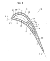
- FIG. 4 shows a cross section of an approximately center portion of a stationary blade of a second row (row 2) (hereinafter, referred to as a turbine blade) equipped in a turbine unit (not shown) along with the plane substantially perpendicular to an axial line in a vertical or upright direction.
- a typical example of a turbine blade 10 shown in FIG. 4 comprises a turbine blade body 20 and inserts 30.
- a leading edge 'L.E.' is connected with a trailing edge 'T.E.' by a 'curved' center line 'C.L.'.
- a sheet of a plate-like rib 22 is arranged substantially perpendicular to the center line C.L. and partitions the interior space of the turbine blade 20 into two cavities C1 and C2.
- Air holes 24 having pin fins 23 are arranged with respect to the cavity C2 that is arranged in the side of the trailing edge T.E., wherein they force the cooling air in the cavity C2 to flow towards the exterior of the turbine blade body 20.
- the insert 30 has a hollow shape and provides the prescribed number of impingement cooling holes 31.
- One insert 30 is inserted into each of the cavities C1 and C2 in such a way that a cooling space C.S. is formed between an exterior surface 32 of the insert 30 and an interior surface 25 of the turbine blade body 20.
- the cooling air is introduced into the internal spaces of the inserts 30 by a specific means (not shown); then, the cooling air is forced to flow into the cooling spaces C.S. through the impingement holes 31 as shown by solid arrows in FIG. 5, so that the turbine blade body 20 is subjected to impingement cooling. Then, the cooling air is further forced to flow outwards through plural film cooling holes 21 arranged in exterior walls of the turbine blade body 20. This causes film layers formed around exterior walls of the turbine blade body 20 due to the cooling air, so that the turbine blade body 20 is subjected to film cooling.
- the cooling air spurts out through the air holes 24 from the trailing edge T.E.
- the proximal portion of the trailing edge T.E. of the turbine blade body 20 is cooled down by the cooling air cooling the pin fins 23.
- the cooling efficiency may be deteriorated with respect to the pin fins 23 that are arranged in proximity to the trailing edge T.E. of the turbine blade body 20. This causes a problem in that in order to cool down the pin fins 23, a considerable amount of cooling air should be forced to spurt out from the impingement cooling holes 31 of the insert 30 that is arranged in the cavity C2.
- a turbine blade applicable to a gas turbine has a turbine blade body having film cooling holes, the interior space of which is partitioned into two cavities by a rib having a plate-like shape.
- the rib is arranged substantially perpendicular to the center line connecting between the leading edge and trailing edge in the plane substantially perpendicular to the axial line of the turbine blade body in the vertical direction.
- Inserts are respectively arranged in the cavities in such a way that the cooling space is formed between the exterior surface of the insert and the interior surface of the turbine blade body.
- the inserts each have a hollow shape and impingement holes.
- a communication means such as bypass holes and slit(s) is formed with the rib to provide a communication between the cavity arranged in the leading-edge side and the cavity arranged in the trailing-edge side in the turbine blade body.
- the cooling air that is introduced into the inserts is forced to flow into the cooling spaces via the impingement holes.
- the turbine blade body is subjected to impingement cooling.
- the cooling air spurts out from the film cooling holes, thus forming film layers around the turbine blade body.
- the turbine blade body is subjected to film cooling.
- a part of the cooling air in the cooling space arranged in the leading-edge side is guided and is forced to flow into the cooling space arranged in the trailing-edge side. Therefore, it contributes to the cooling of the cooling space arranged in the trailing-edge side.
- the cooling air transmitted through the communication means formed with the rib is transmitting through and is cooling the cooling space arranged in the trailing-edge side; then, it is forced to flow out from the trailing edge of the turbine blade body while cooling pin fins.
- the communication means is arranged in either the rear side or front side, which has a good heat transmission in the turbine blade body. That is, the impingement cooling is interrupted with respect to the prescribed side having a good heat transmission compared with the other side in the turbine blade body.
- a partition wall can be arranged between the rib and the insert arranged in the trailing-edge side, thus providing a separation between the cooling space arranged in the rear side and the cooling space arranged in the front side in the turbine blade body. That is, it is possible to prevent the cooling air transmitted through the communication means from proceeding to the cooling space of the front side (or rear side) from the cooling space of the rear side (or front side). In other words, it is possible to prevent the impingement cooling of the front side (or rear side) from being interrupted by the cooling space that is transmitted through the communication means from the rear side (or front side) in the turbine blade body.
- FIG. 1 shows a cross section showing an approximately center portion of a stationary blade of a second row (row 2) (hereinafter, referred to as a turbine blade) equipped in a turbine (not shown) along with the plane substantially perpendicular to an axial line in a vertical direction.
- a turbine blade 100 shown in FIG. 1 comprises a turbine blade body 120 and two inserts 30.
- a leading edge 'L.E.' is connected with a trailing edge 'T.E.' by a 'curved' center line 'C.L.'.
- the turbine blade body 120 has film cooling holes 121 and a sheet of a plate-like rib 122 that is arranged substantially perpendicular to the center line C.L. and partitions the interior space of the turbine blade 120 into two cavities C1 and C2.
- Air holes 24 having pin fins 23 are arranged with respect to the cavity C2 that is arranged in the side of the trailing edge T.E., wherein they force the cooling air in the cavity C2 to flow towards the exterior of the turbine blade body 20.
- a communication means 140 is arranged in a rear side 126 of the turbine blade body 120 to provide a communication between the cavity C1 arranged in the side of the leading edge L.E. and the cavity C2 arranged in the side of the trailing edge T.E.
- the insert 30 has a hollow shape and provides the prescribed number of impingement cooling holes 31.
- One insert 30 is inserted into each of the cavities C1 and C2 in such a way that a cooling space C.S. is formed between an exterior surface 32 of the insert 30 and an interior surface 125 of the turbine blade body 120.
- the cooling air is introduced into the internal space of the inserts 30 by a specific means (not shown); then, the cooling air is forced to flow into the cooling spaces C.S. through the impingement holes 31 as shown by sold arrows in FIG. 2, so that the turbine blade body 120 is subjected to impingement cooling. Then, the cooling air is further forced to flow outwards through the film cooling holes 121 of the turbine blade body 120. This causes film layers formed around exterior walls of the turbine blade body 120 due to the cooling air, so that the turbine blade body 120 is subjected to film cooling.
- the cooling air spurts out through the air holes 124 from the trailing edge T.E. of the turbine blade body 120.
- the proximal portion of the trailing edge T.E. of the turbine blade body 120 are cooled down by the cooling air cooling the pin fins 123.
- the aforementioned communication means 140 can be realized by plural bypass holes that penetrate through the rib 122 in its thickness direction and that are arranged along the axial line (perpendicular to the drawing sheet) of the turbine blade body 120 in the vertical direction.
- the communication means 140 can be realized by at least one slit that penetrates through the rib 122 in its thickness direction and that is arranged along the axial line (perpendicular to the drawing sheet) of the turbine blade body 120 in the vertical direction.
- the aforementioned communication means 140 may be preferably arranged either the rear side 126 or a front side 127, which is superior in heat transmission.
- the communication means By arranging the communication means in the prescribed side having a good heat transmission, it is possible to block the impingement cooling in the prescribed side having a good heat transmission. That is, it is possible to reduce temperature differences between the prescribed side having a good heat transmission and the other side.
- the present embodiment is not necessarily limited in such a way that the communication means 140 is solely arranged for the turbine blade body 120 in either the rear side 126 or front side 127, which is superior in heat transmission. Instead, it is possible to arrange communication means both at the rear side 126 and front side 127 of the turbine blade body 120.
- One solution is to provide the greater number of bypass holes or slits in the prescribed side having a good heat transmission compared with the other side.
- a partition wall 150 between the rib 122 and the insert 30 arranged in the side of the trailing edge T.E. as shown in FIG. 3, wherein the partition wall 150 separates the cooling space C.S. in the rear side 126 of the turbine blade body 120 and the cooling space C.S. in the front side 127 of the turbine blade body 120.
- partition wall 150 It is possible to integrally form the partition wall 150 with the rib 122 or the insert 30 arranged in the side of the trailing edge T.E. Alternatively, the partition wall 150 can be formed independently of the rib 122 or the insert 30.
- partition wall 150 can be formed like a seal dam, which is conventionally known, as necessary.
- the cooling air transmitted through the communication means 140 is forced to flow towards the air holes 124 through only the cooling space C.S. arranged in the rear side of the turbine blade body 120. That is, the partition wall 150 prevents the cooling air transmitted through the communication means 140 from proceeding to the cooling space C.S. arranged in the rear side 126 of the turbine blade body 120. Therefore, it is possible to prevent the impingement cooling in the cooling space C.S. arranged in the front side 127 from being interrupted due to the the cooling air transmitted through the communication means 140.
- This invention is not necessarily used for the stationary blade in the second row (row 2). Therefore, it can be applied to stationary blades of other rows as well as moving blades in the gas turbine as necessary.
- this invention is not necessarily applicable to the prescribed structure of the turbine blade having two cavities partitioned by one rib. Hence, this invention is applicable to other types of turbine blades having three or more cavities partitioned by two or more ribs.
- a gas turbine comprises a turbine, a compressor for compressing combustion air, and a combustion chamber for combining the combustion air with fuel to bum, thus producing high-temperature combustion gas, wherein the turbine is designed to use the aforementioned examples of the turbine blades.
- this invention has a variety of technical features and effects, which will be described below.
Landscapes
- Engineering & Computer Science (AREA)
- Mechanical Engineering (AREA)
- General Engineering & Computer Science (AREA)
- Turbine Rotor Nozzle Sealing (AREA)
Applications Claiming Priority (2)
| Application Number | Priority Date | Filing Date | Title |
|---|---|---|---|
| US10/192,676 US6742991B2 (en) | 2002-07-11 | 2002-07-11 | Turbine blade and gas turbine |
| US192676 | 2002-07-11 |
Publications (3)
| Publication Number | Publication Date |
|---|---|
| EP1380724A2 true EP1380724A2 (de) | 2004-01-14 |
| EP1380724A3 EP1380724A3 (de) | 2006-11-02 |
| EP1380724B1 EP1380724B1 (de) | 2012-12-05 |
Family
ID=29735308
Family Applications (1)
| Application Number | Title | Priority Date | Filing Date |
|---|---|---|---|
| EP03012835A Expired - Lifetime EP1380724B1 (de) | 2002-07-11 | 2003-06-05 | Gekühlte Turbinenschaufel |
Country Status (5)
| Country | Link |
|---|---|
| US (1) | US6742991B2 (de) |
| EP (1) | EP1380724B1 (de) |
| JP (1) | JP4070621B2 (de) |
| CN (1) | CN1477292B (de) |
| CA (1) | CA2432685C (de) |
Cited By (12)
| Publication number | Priority date | Publication date | Assignee | Title |
|---|---|---|---|---|
| EP1921269A1 (de) * | 2006-11-09 | 2008-05-14 | Siemens Aktiengesellschaft | Turbinenschaufel |
| GB2452327A (en) * | 2007-09-01 | 2009-03-04 | Rolls Royce Plc | A component having a cooling passage comprising interconnected chambers |
| CN101482029A (zh) * | 2008-01-10 | 2009-07-15 | 通用电气公司 | 涡轮叶片叶冠 |
| CN101482031A (zh) * | 2008-01-10 | 2009-07-15 | 通用电气公司 | 涡轮叶片叶冠 |
| EP2628901A1 (de) * | 2012-02-15 | 2013-08-21 | Siemens Aktiengesellschaft | Turbinenschaufel mit Prallkühlung |
| WO2014047022A1 (en) | 2012-09-18 | 2014-03-27 | United Technologies Corporation | Gas turbine engine component cooling circuit |
| EP2204538A3 (de) * | 2008-12-30 | 2014-10-08 | General Electric Company | Turbinenschaufelkühlkreisläufe |
| WO2015195088A1 (en) * | 2014-06-17 | 2015-12-23 | Siemens Energy, Inc. | Turbine airfoil cooling system with leading edge impingement cooling system |
| EP3269931A1 (de) * | 2012-10-03 | 2018-01-17 | Rolls-Royce plc | Gasturbinenmotorkomponente |
| EP3508692A1 (de) * | 2018-01-05 | 2019-07-10 | United Technologies Corporation | Schaufel mit rippenkommunikation-öffnungen |
| EP3508694A1 (de) * | 2018-01-05 | 2019-07-10 | United Technologies Corporation | Gasturbinenmotorschaufel mit kühlstrecke |
| EP3663517A1 (de) * | 2018-12-05 | 2020-06-10 | United Technologies Corporation | Hülle, zugehöriges bauteil und gasturbinentriebwerk |
Families Citing this family (46)
| Publication number | Priority date | Publication date | Assignee | Title |
|---|---|---|---|---|
| ATE513980T1 (de) * | 2004-12-24 | 2011-07-15 | Alstom Technology Ltd | Verfahren zur herstellung eines bauteils mit eingebettetem kanal sowie bauteil |
| US7303376B2 (en) * | 2005-12-02 | 2007-12-04 | Siemens Power Generation, Inc. | Turbine airfoil with outer wall cooling system and inner mid-chord hot gas receiving cavity |
| US7497655B1 (en) | 2006-08-21 | 2009-03-03 | Florida Turbine Technologies, Inc. | Turbine airfoil with near-wall impingement and vortex cooling |
| US7556476B1 (en) * | 2006-11-16 | 2009-07-07 | Florida Turbine Technologies, Inc. | Turbine airfoil with multiple near wall compartment cooling |
| US7871246B2 (en) * | 2007-02-15 | 2011-01-18 | Siemens Energy, Inc. | Airfoil for a gas turbine |
| WO2009016744A1 (ja) * | 2007-07-31 | 2009-02-05 | Mitsubishi Heavy Industries, Ltd. | タービン用翼 |
| JP2009197650A (ja) * | 2008-02-20 | 2009-09-03 | Mitsubishi Heavy Ind Ltd | ガスタービン |
| US8066483B1 (en) * | 2008-12-18 | 2011-11-29 | Florida Turbine Technologies, Inc. | Turbine airfoil with non-parallel pin fins |
| US8167537B1 (en) * | 2009-01-09 | 2012-05-01 | Florida Turbine Technologies, Inc. | Air cooled turbine airfoil with sequential impingement cooling |
| US8182223B2 (en) * | 2009-02-27 | 2012-05-22 | General Electric Company | Turbine blade cooling |
| US8152468B2 (en) * | 2009-03-13 | 2012-04-10 | United Technologies Corporation | Divoted airfoil baffle having aimed cooling holes |
| EP2431573B1 (de) | 2009-05-11 | 2014-12-03 | Mitsubishi Heavy Industries, Ltd. | Turbinenleitschaufel und gasturbine |
| JP2011085084A (ja) | 2009-10-16 | 2011-04-28 | Ihi Corp | タービン翼 |
| US9528382B2 (en) * | 2009-11-10 | 2016-12-27 | General Electric Company | Airfoil heat shield |
| EP2333240B1 (de) * | 2009-12-03 | 2013-02-13 | Alstom Technology Ltd | Zweigeteilte Turbinenschaufel mit verbesserten Kühlungs- und Schwingungseigenschaften |
| CN101825115B (zh) * | 2010-03-31 | 2011-09-28 | 北京航空航天大学 | 一种内置排骨架式气动阻尼的叶片 |
| US8449249B2 (en) | 2010-04-09 | 2013-05-28 | Williams International Co., L.L.C. | Turbine nozzle apparatus and associated method of manufacture |
| JP2012202335A (ja) * | 2011-03-25 | 2012-10-22 | Mitsubishi Heavy Ind Ltd | インピンジメント冷却構造、及び、それを用いたガスタービン静翼 |
| US9151173B2 (en) | 2011-12-15 | 2015-10-06 | General Electric Company | Use of multi-faceted impingement openings for increasing heat transfer characteristics on gas turbine components |
| WO2015002976A1 (en) * | 2013-07-01 | 2015-01-08 | United Technologies Corporation | Airfoil, and method for manufacturing the same |
| EP3060764B1 (de) * | 2013-10-21 | 2019-06-26 | United Technologies Corporation | Fehlertolerante turbinenschaufelkühlung |
| JP6245740B2 (ja) * | 2013-11-20 | 2017-12-13 | 三菱日立パワーシステムズ株式会社 | ガスタービン翼 |
| US9957816B2 (en) * | 2014-05-29 | 2018-05-01 | General Electric Company | Angled impingement insert |
| US9850763B2 (en) | 2015-07-29 | 2017-12-26 | General Electric Company | Article, airfoil component and method for forming article |
| US20170130589A1 (en) * | 2015-11-05 | 2017-05-11 | General Electric Company | Article, component, and method of cooling a component |
| US10704395B2 (en) * | 2016-05-10 | 2020-07-07 | General Electric Company | Airfoil with cooling circuit |
| US10655477B2 (en) | 2016-07-26 | 2020-05-19 | General Electric Company | Turbine components and method for forming turbine components |
| US10895158B2 (en) | 2016-07-28 | 2021-01-19 | Siemens Aktiengesellschaft | Turbine airfoil with independent cooling circuit for mid-body temperature control |
| US10443397B2 (en) * | 2016-08-12 | 2019-10-15 | General Electric Company | Impingement system for an airfoil |
| US10364685B2 (en) * | 2016-08-12 | 2019-07-30 | Gneral Electric Company | Impingement system for an airfoil |
| US10436048B2 (en) * | 2016-08-12 | 2019-10-08 | General Electric Comapny | Systems for removing heat from turbine components |
| US10408062B2 (en) * | 2016-08-12 | 2019-09-10 | General Electric Company | Impingement system for an airfoil |
| KR20180065728A (ko) * | 2016-12-08 | 2018-06-18 | 두산중공업 주식회사 | 베인의 냉각 구조 |
| US10260363B2 (en) | 2016-12-08 | 2019-04-16 | General Electric Company | Additive manufactured seal for insert compartmentalization |
| US10480327B2 (en) * | 2017-01-03 | 2019-11-19 | General Electric Company | Components having channels for impingement cooling |
| US10815806B2 (en) * | 2017-06-05 | 2020-10-27 | General Electric Company | Engine component with insert |
| RU2663966C1 (ru) * | 2017-11-14 | 2018-08-13 | федеральное государственное бюджетное образовательное учреждение высшего образования "Национальный исследовательский университет "МЭИ" (ФГБОУ ВО "НИУ "МЭИ") | Охлаждаемая лопатка соплового аппарата газовой турбины |
| US10934854B2 (en) * | 2018-09-11 | 2021-03-02 | General Electric Company | CMC component cooling cavities |
| RU2686244C1 (ru) * | 2018-11-13 | 2019-04-24 | федеральное государственное бюджетное образовательное учреждение высшего образования "Национальный исследовательский университет "МЭИ" (ФГБОУ ВО "НИУ "МЭИ") | Охлаждаемая лопатка газовой турбины |
| US10822963B2 (en) | 2018-12-05 | 2020-11-03 | Raytheon Technologies Corporation | Axial flow cooling scheme with castable structural rib for a gas turbine engine |
| CN109812301A (zh) * | 2019-03-06 | 2019-05-28 | 上海交通大学 | 一种具有横向通气孔的涡轮叶片双层壁冷却结构 |
| CN110925028B (zh) * | 2019-12-05 | 2022-06-07 | 中国航发四川燃气涡轮研究院 | 一种带s形冲击腔隔板的燃气涡轮机涡轮叶片 |
| CN111156053A (zh) * | 2020-01-14 | 2020-05-15 | 南京航空航天大学 | 一种基于燃气涡轮叶片的尾缘偏劈缝结构及冷却方法 |
| WO2021193610A1 (ja) * | 2020-03-25 | 2021-09-30 | 三菱パワー株式会社 | タービン翼 |
| CN112160796B (zh) * | 2020-09-03 | 2022-09-09 | 哈尔滨工业大学 | 燃气轮机发动机的涡轮叶片及其控制方法 |
| CN112282858B (zh) * | 2020-11-11 | 2024-05-24 | 哈尔滨工业大学(深圳) | 一种基于记忆合金的燃气透平叶片冷却结构 |
Family Cites Families (12)
| Publication number | Priority date | Publication date | Assignee | Title |
|---|---|---|---|---|
| GB1400285A (en) * | 1972-08-02 | 1975-07-16 | Rolls Royce | Hollow cooled vane or blade for a gas turbine engine |
| GB1587401A (en) * | 1973-11-15 | 1981-04-01 | Rolls Royce | Hollow cooled vane for a gas turbine engine |
| US4297077A (en) * | 1979-07-09 | 1981-10-27 | Westinghouse Electric Corp. | Cooled turbine vane |
| JP3142850B2 (ja) * | 1989-03-13 | 2001-03-07 | 株式会社東芝 | タービンの冷却翼および複合発電プラント |
| US5246340A (en) * | 1991-11-19 | 1993-09-21 | Allied-Signal Inc. | Internally cooled airfoil |
| JP3110227B2 (ja) * | 1993-11-22 | 2000-11-20 | 株式会社東芝 | タービン冷却翼 |
| JPH09507550A (ja) | 1994-10-24 | 1997-07-29 | ウエスチングハウス・エレクトリック・コーポレイション | 冷却効率の高いガスタービン翼 |
| JP3897402B2 (ja) * | 1997-06-13 | 2007-03-22 | 三菱重工業株式会社 | ガスタービン静翼インサート挿入構造及び方法 |
| US6193465B1 (en) * | 1998-09-28 | 2001-02-27 | General Electric Company | Trapped insert turbine airfoil |
| EP1101901A1 (de) * | 1999-11-16 | 2001-05-23 | Siemens Aktiengesellschaft | Turbinenschaufel sowie Verfahren zur Herstellung einer Turbinenschaufel |
| GB0025012D0 (en) * | 2000-10-12 | 2000-11-29 | Rolls Royce Plc | Cooling of gas turbine engine aerofoils |
| DE50010300D1 (de) * | 2000-11-16 | 2005-06-16 | Siemens Ag | Gasturbinenschaufel |
-
2002
- 2002-07-11 US US10/192,676 patent/US6742991B2/en not_active Expired - Lifetime
-
2003
- 2003-01-24 JP JP2003016736A patent/JP4070621B2/ja not_active Expired - Lifetime
- 2003-06-05 EP EP03012835A patent/EP1380724B1/de not_active Expired - Lifetime
- 2003-06-13 CN CN031423388A patent/CN1477292B/zh not_active Expired - Lifetime
- 2003-06-18 CA CA002432685A patent/CA2432685C/en not_active Expired - Lifetime
Non-Patent Citations (1)
| Title |
|---|
| None |
Cited By (24)
| Publication number | Priority date | Publication date | Assignee | Title |
|---|---|---|---|---|
| US8215909B2 (en) | 2006-11-09 | 2012-07-10 | Siemens Aktiengesellschaft | Turbine blade |
| WO2008055764A1 (de) * | 2006-11-09 | 2008-05-15 | Siemens Aktiengesellschaft | Turbinenschaufel |
| EP1921269A1 (de) * | 2006-11-09 | 2008-05-14 | Siemens Aktiengesellschaft | Turbinenschaufel |
| GB2452327A (en) * | 2007-09-01 | 2009-03-04 | Rolls Royce Plc | A component having a cooling passage comprising interconnected chambers |
| US8262355B2 (en) | 2007-09-01 | 2012-09-11 | Rolls-Royce Plc | Cooled component |
| GB2452327B (en) * | 2007-09-01 | 2010-02-03 | Rolls Royce Plc | A cooled component |
| CN101482029B (zh) * | 2008-01-10 | 2014-08-27 | 通用电气公司 | 涡轮叶片叶冠 |
| CN101482031B (zh) * | 2008-01-10 | 2014-01-08 | 通用电气公司 | 涡轮叶片叶冠 |
| CN101482029A (zh) * | 2008-01-10 | 2009-07-15 | 通用电气公司 | 涡轮叶片叶冠 |
| CN101482031A (zh) * | 2008-01-10 | 2009-07-15 | 通用电气公司 | 涡轮叶片叶冠 |
| EP2204538A3 (de) * | 2008-12-30 | 2014-10-08 | General Electric Company | Turbinenschaufelkühlkreisläufe |
| EP2628901A1 (de) * | 2012-02-15 | 2013-08-21 | Siemens Aktiengesellschaft | Turbinenschaufel mit Prallkühlung |
| WO2013120552A1 (en) * | 2012-02-15 | 2013-08-22 | Siemens Aktiengesellschaft | Impingement cooling of turbine blades or vanes |
| US9863255B2 (en) | 2012-02-15 | 2018-01-09 | Siemens Aktiengesellschaft | Impingement cooling of turbine blades or vanes |
| WO2014047022A1 (en) | 2012-09-18 | 2014-03-27 | United Technologies Corporation | Gas turbine engine component cooling circuit |
| EP2898203A4 (de) * | 2012-09-18 | 2015-11-25 | United Technologies Corp | Kühlsystem für gasturbinenbauteile |
| EP3269931A1 (de) * | 2012-10-03 | 2018-01-17 | Rolls-Royce plc | Gasturbinenmotorkomponente |
| WO2015195088A1 (en) * | 2014-06-17 | 2015-12-23 | Siemens Energy, Inc. | Turbine airfoil cooling system with leading edge impingement cooling system |
| EP3508692A1 (de) * | 2018-01-05 | 2019-07-10 | United Technologies Corporation | Schaufel mit rippenkommunikation-öffnungen |
| EP3508694A1 (de) * | 2018-01-05 | 2019-07-10 | United Technologies Corporation | Gasturbinenmotorschaufel mit kühlstrecke |
| US10746026B2 (en) | 2018-01-05 | 2020-08-18 | Raytheon Technologies Corporation | Gas turbine engine airfoil with cooling path |
| US11261739B2 (en) | 2018-01-05 | 2022-03-01 | Raytheon Technologies Corporation | Airfoil with rib communication |
| EP3663517A1 (de) * | 2018-12-05 | 2020-06-10 | United Technologies Corporation | Hülle, zugehöriges bauteil und gasturbinentriebwerk |
| US10815794B2 (en) | 2018-12-05 | 2020-10-27 | Raytheon Technologies Corporation | Baffle for components of gas turbine engines |
Also Published As
| Publication number | Publication date |
|---|---|
| US6742991B2 (en) | 2004-06-01 |
| US20040009066A1 (en) | 2004-01-15 |
| JP4070621B2 (ja) | 2008-04-02 |
| CA2432685A1 (en) | 2004-01-11 |
| EP1380724B1 (de) | 2012-12-05 |
| CN1477292B (zh) | 2010-06-02 |
| CN1477292A (zh) | 2004-02-25 |
| CA2432685C (en) | 2007-09-04 |
| JP2004044572A (ja) | 2004-02-12 |
| EP1380724A3 (de) | 2006-11-02 |
Similar Documents
| Publication | Publication Date | Title |
|---|---|---|
| US6742991B2 (en) | Turbine blade and gas turbine | |
| KR101180547B1 (ko) | 터빈용 날개 | |
| US7549844B2 (en) | Turbine airfoil cooling system with bifurcated and recessed trailing edge exhaust channels | |
| EP1384855B1 (de) | Kühlstruktur einer Turbinenleitschaufel und Gasturbine | |
| US7121787B2 (en) | Turbine nozzle trailing edge cooling configuration | |
| KR101670618B1 (ko) | 분할 링 냉각 구조 | |
| US20100221121A1 (en) | Turbine airfoil cooling system with near wall pin fin cooling chambers | |
| CA1211052A (en) | Turbine blade | |
| US9765642B2 (en) | Interior cooling circuits in turbine blades | |
| JP2009162119A (ja) | タービン翼の冷却構造 | |
| US8596976B2 (en) | Turbine blade | |
| US20130084191A1 (en) | Turbine blade with impingement cavity cooling including pin fins | |
| EP3114322A1 (de) | Turbinenschaufel | |
| JP2009041433A (ja) | ガスタービン翼 | |
| US9879547B2 (en) | Interior cooling circuits in turbine blades | |
| JP5078766B2 (ja) | タービン静翼構造 | |
| US9562437B2 (en) | Turbine blade airfoils including film cooling systems, and methods for forming an improved film cooled airfoil of a turbine blade | |
| JP2006336647A (ja) | タービンブレード冷却系 | |
| CN113931702B (zh) | 燃气轮机、导向叶片及其导叶缘板 | |
| JP3642537B2 (ja) | ガスタービン冷却翼 | |
| CN115324653B (zh) | 用于燃气轮机的双层壁叶片和燃气轮机 | |
| US10900361B2 (en) | Turbine airfoil with biased trailing edge cooling arrangement | |
| JP2003056301A (ja) | タービン翼部品 | |
| JPH11173105A (ja) | ガスタービン動翼 | |
| JPH1162504A (ja) | タービン翼の二重壁冷却構造 |
Legal Events
| Date | Code | Title | Description |
|---|---|---|---|
| PUAI | Public reference made under article 153(3) epc to a published international application that has entered the european phase |
Free format text: ORIGINAL CODE: 0009012 |
|
| 17P | Request for examination filed |
Effective date: 20030605 |
|
| AK | Designated contracting states |
Kind code of ref document: A2 Designated state(s): AT BE BG CH CY CZ DE DK EE ES FI FR GB GR HU IE IT LI LU MC NL PT RO SE SI SK TR |
|
| AX | Request for extension of the european patent |
Extension state: AL LT LV MK |
|
| PUAL | Search report despatched |
Free format text: ORIGINAL CODE: 0009013 |
|
| AK | Designated contracting states |
Kind code of ref document: A3 Designated state(s): AT BE BG CH CY CZ DE DK EE ES FI FR GB GR HU IE IT LI LU MC NL PT RO SE SI SK TR |
|
| AX | Request for extension of the european patent |
Extension state: AL LT LV MK |
|
| 17Q | First examination report despatched |
Effective date: 20070420 |
|
| AKX | Designation fees paid |
Designated state(s): CH DE FR GB IT LI |
|
| GRAP | Despatch of communication of intention to grant a patent |
Free format text: ORIGINAL CODE: EPIDOSNIGR1 |
|
| GRAS | Grant fee paid |
Free format text: ORIGINAL CODE: EPIDOSNIGR3 |
|
| GRAA | (expected) grant |
Free format text: ORIGINAL CODE: 0009210 |
|
| AK | Designated contracting states |
Kind code of ref document: B1 Designated state(s): CH DE FR GB IT LI |
|
| REG | Reference to a national code |
Ref country code: GB Ref legal event code: FG4D Ref country code: DE Ref legal event code: R081 Ref document number: 60342738 Country of ref document: DE Owner name: MITSUBISHI HITACHI POWER SYSTEMS, LTD., YOKOHA, JP Free format text: FORMER OWNER: MITSUBISHI HEAVY INDUSTRIES, LTD., TOKIO/TOKYO, JP |
|
| REG | Reference to a national code |
Ref country code: CH Ref legal event code: EP |
|
| REG | Reference to a national code |
Ref country code: DE Ref legal event code: R096 Ref document number: 60342738 Country of ref document: DE Effective date: 20130131 |
|
| PLBE | No opposition filed within time limit |
Free format text: ORIGINAL CODE: 0009261 |
|
| STAA | Information on the status of an ep patent application or granted ep patent |
Free format text: STATUS: NO OPPOSITION FILED WITHIN TIME LIMIT |
|
| 26N | No opposition filed |
Effective date: 20130906 |
|
| PG25 | Lapsed in a contracting state [announced via postgrant information from national office to epo] |
Ref country code: IT Free format text: LAPSE BECAUSE OF FAILURE TO SUBMIT A TRANSLATION OF THE DESCRIPTION OR TO PAY THE FEE WITHIN THE PRESCRIBED TIME-LIMIT Effective date: 20121205 |
|
| REG | Reference to a national code |
Ref country code: DE Ref legal event code: R097 Ref document number: 60342738 Country of ref document: DE Effective date: 20130906 |
|
| REG | Reference to a national code |
Ref country code: CH Ref legal event code: PL |
|
| GBPC | Gb: european patent ceased through non-payment of renewal fee |
Effective date: 20130605 |
|
| REG | Reference to a national code |
Ref country code: FR Ref legal event code: ST Effective date: 20140228 |
|
| PG25 | Lapsed in a contracting state [announced via postgrant information from national office to epo] |
Ref country code: LI Free format text: LAPSE BECAUSE OF NON-PAYMENT OF DUE FEES Effective date: 20130630 Ref country code: GB Free format text: LAPSE BECAUSE OF NON-PAYMENT OF DUE FEES Effective date: 20130605 Ref country code: CH Free format text: LAPSE BECAUSE OF NON-PAYMENT OF DUE FEES Effective date: 20130630 |
|
| PG25 | Lapsed in a contracting state [announced via postgrant information from national office to epo] |
Ref country code: FR Free format text: LAPSE BECAUSE OF NON-PAYMENT OF DUE FEES Effective date: 20130701 |
|
| REG | Reference to a national code |
Ref country code: DE Ref legal event code: R082 Ref document number: 60342738 Country of ref document: DE Representative=s name: PATENTANWAELTE HENKEL, BREUER & PARTNER, DE Ref country code: DE Ref legal event code: R081 Ref document number: 60342738 Country of ref document: DE Owner name: MITSUBISHI HITACHI POWER SYSTEMS, LTD., YOKOHA, JP Free format text: FORMER OWNER: MITSUBISHI HEAVY INDUSTRIES, LTD., TOKYO, JP Ref country code: DE Ref legal event code: R082 Ref document number: 60342738 Country of ref document: DE Representative=s name: PATENTANWAELTE HENKEL, BREUER & PARTNER MBB, DE |
|
| REG | Reference to a national code |
Ref country code: DE Ref legal event code: R082 Ref document number: 60342738 Country of ref document: DE Representative=s name: PATENTANWAELTE HENKEL, BREUER & PARTNER, DE Effective date: 20150601 Ref country code: DE Ref legal event code: R081 Ref document number: 60342738 Country of ref document: DE Owner name: MITSUBISHI HITACHI POWER SYSTEMS, LTD., YOKOHA, JP Free format text: FORMER OWNER: MITSUBISHI HEAVY INDUSTRIES, LTD., TOKIO/TOKYO, JP Effective date: 20121205 Ref country code: DE Ref legal event code: R081 Ref document number: 60342738 Country of ref document: DE Owner name: MITSUBISHI HITACHI POWER SYSTEMS, LTD., YOKOHA, JP Free format text: FORMER OWNER: MITSUBISHI HEAVY INDUSTRIES, LTD., TOKYO, JP Effective date: 20150601 |
|
| PGFP | Annual fee paid to national office [announced via postgrant information from national office to epo] |
Ref country code: DE Payment date: 20220505 Year of fee payment: 20 |
|
| REG | Reference to a national code |
Ref country code: DE Ref legal event code: R071 Ref document number: 60342738 Country of ref document: DE |