EP1380762A1 - Biegeausgleichswalze mit vormontierter Ölverteilungseinheit im Joch - Google Patents
Biegeausgleichswalze mit vormontierter Ölverteilungseinheit im Joch Download PDFInfo
- Publication number
- EP1380762A1 EP1380762A1 EP03014081A EP03014081A EP1380762A1 EP 1380762 A1 EP1380762 A1 EP 1380762A1 EP 03014081 A EP03014081 A EP 03014081A EP 03014081 A EP03014081 A EP 03014081A EP 1380762 A1 EP1380762 A1 EP 1380762A1
- Authority
- EP
- European Patent Office
- Prior art keywords
- cladding tube
- bending compensation
- roller according
- compensation roller
- yoke
- Prior art date
- Legal status (The legal status is an assumption and is not a legal conclusion. Google has not performed a legal analysis and makes no representation as to the accuracy of the status listed.)
- Granted
Links
- 238000005253 cladding Methods 0.000 claims abstract description 61
- 239000012530 fluid Substances 0.000 claims abstract description 30
- 229910000831 Steel Inorganic materials 0.000 claims abstract description 9
- 239000010959 steel Substances 0.000 claims abstract description 9
- 238000005452 bending Methods 0.000 claims description 51
- 239000002826 coolant Substances 0.000 claims description 18
- 238000010276 construction Methods 0.000 claims description 3
- 239000004033 plastic Substances 0.000 claims description 3
- 229920003023 plastic Polymers 0.000 claims description 3
- 229920002635 polyurethane Polymers 0.000 claims description 3
- 239000004814 polyurethane Substances 0.000 claims description 3
- 238000003466 welding Methods 0.000 abstract description 2
- 238000007789 sealing Methods 0.000 description 3
- 230000007797 corrosion Effects 0.000 description 2
- 238000005260 corrosion Methods 0.000 description 2
- 238000009499 grossing Methods 0.000 description 2
- 238000001816 cooling Methods 0.000 description 1
- 238000005553 drilling Methods 0.000 description 1
- 230000007257 malfunction Effects 0.000 description 1
- 230000000149 penetrating effect Effects 0.000 description 1
- 238000003825 pressing Methods 0.000 description 1
- 229910001220 stainless steel Inorganic materials 0.000 description 1
- 239000010935 stainless steel Substances 0.000 description 1
Images


Classifications
-
- F—MECHANICAL ENGINEERING; LIGHTING; HEATING; WEAPONS; BLASTING
- F16—ENGINEERING ELEMENTS AND UNITS; GENERAL MEASURES FOR PRODUCING AND MAINTAINING EFFECTIVE FUNCTIONING OF MACHINES OR INSTALLATIONS; THERMAL INSULATION IN GENERAL
- F16C—SHAFTS; FLEXIBLE SHAFTS; ELEMENTS OR CRANKSHAFT MECHANISMS; ROTARY BODIES OTHER THAN GEARING ELEMENTS; BEARINGS
- F16C13/00—Rolls, drums, discs, or the like; Bearings or mountings therefor
- F16C13/02—Bearings
- F16C13/022—Bearings supporting a hollow roll mantle rotating with respect to a yoke or axle
- F16C13/024—Bearings supporting a hollow roll mantle rotating with respect to a yoke or axle adjustable for positioning, e.g. radial movable bearings for controlling the deflection along the length of the roll mantle
- F16C13/026—Bearings supporting a hollow roll mantle rotating with respect to a yoke or axle adjustable for positioning, e.g. radial movable bearings for controlling the deflection along the length of the roll mantle by fluid pressure
- F16C13/028—Bearings supporting a hollow roll mantle rotating with respect to a yoke or axle adjustable for positioning, e.g. radial movable bearings for controlling the deflection along the length of the roll mantle by fluid pressure with a plurality of supports along the length of the roll mantle, e.g. hydraulic jacks
-
- D—TEXTILES; PAPER
- D21—PAPER-MAKING; PRODUCTION OF CELLULOSE
- D21G—CALENDERS; ACCESSORIES FOR PAPER-MAKING MACHINES
- D21G1/00—Calenders; Smoothing apparatus
- D21G1/02—Rolls; Their bearings
- D21G1/0206—Controlled deflection rolls
- D21G1/0213—Controlled deflection rolls with deflection compensation means acting between the roller shell and its supporting member
- D21G1/022—Controlled deflection rolls with deflection compensation means acting between the roller shell and its supporting member the means using fluid pressure
Definitions
- the invention relates to a bending compensation roller with a rotating one Roll shell, a non-rotatable axially penetrating the roller shell Yoke and arranged between the yoke and the roll shell Support elements over an at least partially in an axial bore line system of the yoke can be supplied with pressurized fluid are to a respective support force on the inside of the roll shell exercise.
- a bending compensation roller is used, for example, in Press and smoothing sections of paper machines are used.
- a bending compensation roller known from EP 0 786 054 B1 a variety of intermediate flanges in the Central bore of the yoke used for the corresponding oil distribution each with one of the support elements and the associated oil supply line are connected that the oil from the respective line to the relevant support element is supplied.
- This known roller has among other things, the disadvantage that it is easy to corrosion in particular of the relevant components can come.
- the aim of the invention is to provide an improved bending compensation roller at the beginning to create the type mentioned, in which the aforementioned disadvantages are eliminated.
- the line system comprises at least one preassembled unit, which one into the Axial bore of the yoke insertable cladding tube in which piping coming up to one axial position of the cladding tube, which are in the axial bore of the yoke used cladding tube in the area of at least one respective to be supplied support element, and that on the outer circumference of the Cladding tube extending in the circumferential direction are provided, to between the cladding tube and the inner wall of the axial bore of the Yokes sealed against one another and extending in the circumferential direction Define grooves via which the one supplied by a respective pipeline Pressurized fluid can be supplied to the respective at least one support source.
- the cladding tube is preferably formed by a steel tube. It can in particular through a precision steel tube with all for supply of the supporting elements in question required individual lines be, that including the single-cell lines as complete pre-assembled Unit can be provided, which is then in the axial bore the yoke is inserted.
- the outer diameter of the cladding tube is preferably at least substantially same size as the inside diameter of the axial bore of the Yoke.
- the cladding tube jacket has in the area of the grooves, one hole each, into which the end of the respective pipeline is used.
- the pipe end is in the Hole preferably fixed.
- the bending compensation roller according to the invention is the pipe end welded to the cladding tube in the bore.
- Oil is preferably provided as the pressure fluid.
- the preassembled unit can also, for example, at least comprise a pipe for a coolant.
- a coolant pipe is preferably welded to the cladding tube.
- a coolant oil is preferably provided again.
- the preassembled unit can also have at least one pipeline for the operating fluid or operating oil backflow.
- one such backflow pipeline is preferably again with the cladding tube welded.
- Bending compensation roller is the preassembled unit as a whole formed by a welded structure.
- the cladding tube in the areas between the pipes at least partially, for example with polyurethane or the like, foamed or with Plastic filled or poured out.
- the wetted surface of the Line system can e.g. also coated with a corrosion protection his. It is also possible, for example, to make the entire unit from one stainless steel.
- the webs can be sealed on their outer circumference to seal the grooves Ring seals should be provided. These can e.g. in corresponding Wells can be arranged in the webs. Due to the peelability Such seals on the webs allow wider zones to be realized.
- the pipes can also be made of steel in particular.
- the grooves can also be provided via generally radial channels provided in the yoke be connected to the pressure chambers of the support elements.
- the pressure fluid can the support elements from only one roller end or be fed from both roller ends.
- the support elements can in particular be hydraulic Act support elements.
- Figure 1 shows a schematic longitudinal sectional view of a bending compensation roller 10, for example in a press or smoothing section Paper machine can be used.
- the bending compensation roller 10 comprises a rotating roller shell 12, which is axially penetrated by a rotationally fixed yoke 14. Between the Yoke 14 and roller shell 12 are e.g. hydraulic support elements 16 arranged over an at least partially in an axial bore of the yoke 14 housed line system with pressure fluid, in particular Pressure oil that can be supplied with a respective support force on the inside the roll shell 12 to exercise.
- pressure fluid in particular Pressure oil
- the line system comprises two preassembled units 18 1 , 18 2 , which can be inserted from the two roller ends into an axial bore 20 1 or 20 2 of the yoke 14.
- two blind holes 18 1 , 18 2 which are separate from one another are provided.
- the two preassembled units 18 1 , 18 2 each have a cladding tube 22 that can be inserted into the relevant axial bore 20 1 or 20 2 of the yoke 14, in which the piping 24 coming from the respective outer cladding tube end up to an axial position of the cladding tube 22 1 and 22 2 are guided, which lies after inserting the cladding tubes into the axial bores in the region of a respective support element 16 to be supplied.
- the pressure fluid supplied via the pipelines 24 can be especially oil.
- the two preassembled units 18 1 and 18 2 also each include at least one pipeline 26 for a coolant, in particular oil again, and at least one pipeline 28 for the operating fluid or operating oil return flow.
- FIG. 2 differs from that of FIG. 1 essentially only in that the yoke 14 has a continuous axial bore 20 and the two preassembled units 18 1 , 18 2 are inserted into this one continuous axial bore 20. Corresponding parts are assigned the same reference numerals.
- FIG. 3 shows a further embodiment in a schematic longitudinal sectional illustration the bending compensation roller 10.
- the piping system is only a preassembled unit 18. This is in one through axial bore 20 of the yoke 14 inserted.
- the support elements 16 become Pressure fluid via the pipelines 24 only from the left end of the roll fed while the pipelines 26, 28, in particular the feed the coolant and the operating fluid or operating oil return can serve, are led out of the other roller end. in the In the present case, this results in an asymmetrical piping arrangement.
- the bending compensation roller 10 can at least essentially again the same structure as, for example, that shown in FIG Own roller. Corresponding parts are the same reference numerals assigned.
- FIGS. 4 to 12 Further design options for the respective line systems and in particular the respective preassembled units derive, for example, from the representation of FIGS. 4 to 12, in which purely by way of example again a bending compensation roller 10 with an asymmetrical Pipe arrangement is shown. So here are the support elements 16 again, for example, only from one end of the roll Pressurized fluid supplied.
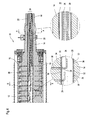
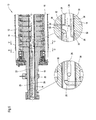
- FIG 4 shows in a more detailed schematic longitudinal section a right part of the relevant bending compensation roller 10 the support elements 12 are shown in FIG The end of the roller is supplied with pressure fluid via the pipelines 24.
- Figure 5 shows a more detailed schematic longitudinal section a left part of the relevant bending compensation roller 12. From the in This roller end shown in Figure 5 is only the pipes 26, 28 for the supply of the coolant or the operating fluid or Operating oil return flow led out.
- the lines running inside the cladding tube 22 can at least partly for example by welding, flanging, pressing and / or the like can be connected to the cladding tube 22.
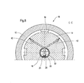
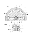
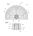
- Figures 6 to 8 and 11 show the bending compensation roller 10 according to the Figures 4 and 5 in schematic cross-sectional views along the Lines A-A to D-D.
- Figure 12 shows a schematic longitudinal sectional view part of the illustration according to FIG. 11.
- this cladding tube 22 are in the present case only from the right cladding tube end forth coming pipelines 24 each up to an axial position of the cladding tube 22, which in the axial bore 20 of the yoke 14th inserted cladding tube 22 in the area of a respective to be supplied Support element 16 lies.
- Support elements 16 may be provided.
- the cladding tube 22 can in particular be formed by a steel tube. It can, for example, a precision steel tube with all for supply of the support elements 16 required individual pipes 24 as pre-assembled unit can be provided.
- the outer diameter of the cladding tube 22 at least essentially the same size as the inner diameter of the axial bore 20 of the yoke 14th
- the one includes a preassembled one Unit 18 all for supplying the relevant support elements 16 required piping 24.
- the cladding tube jacket has a bore 34, in which the end of a respective pipeline 24 is inserted (cf. especially Figures 4 and 5).
- a respective pipeline 24 is inserted (cf. especially Figures 4 and 5).
- support elements 16 are provided, so is for supplying each support element 16 via a respective line 24
- Such a bore 34 is provided.
- a respective groove 32 may be divided circumferentially, i.e. against each other have sealed portions.
- the pipelines 24 initially run from the relevant cladding tube end axially. At their ends they are then e.g. 90 ° to the relevant one Bore 34 bent in the cladding tube.
- the pipe ends are each fixed in the respective bore 34.
- the respective pipe end in the bore 34 with the Cladding tube 22 in particular be welded.
- the preassembled Unit 18 also has at least one pipe 26 for a Coolant, in particular oil, and at least one pipe 28 for the Operating fluid flow or operating oil return flow.
- These pipelines too 26, 28 can in particular be welded to the cladding tube 22 again.
- the preassembled unit 18 can thus be made by a welded construction be educated.
- these pipelines can also be seen, for example open again into grooves 32 defined between webs 30.
- the cladding tube in the areas between the pipes 24, 26, 28 at least partially, e.g. with polyurethane, foamed or with plastic be filled or poured out.
- the webs 30 are on their outer circumference provided with ring seals 36 or piston sealing rings (cf. in particular again Figures 4 and 5).
- the pipes 24, 26, 28 can in particular also be made of steel consist.
- the grooves 32 used to supply the support elements 16 are over generally radial channels 38 with the pressure spaces provided in the yoke 14 connected to the support elements 16 (cf. in particular FIGS. 4 and 5).
- the cladding tube extends 22 of the preassembled unit 18 at least over the length of the Roll shell 12, wherein it is, for example, at least substantially can extend over the entire length of the yoke 14.
- the cladding tube 22 is in the entry area still relatively tightly packed with pipes 24. It can at least essentially the entire inner cross section of the cladding tube 22 be filled with pipes 24.
- FIG. 7 shows an example of a support element 16, the pressure chamber 38 with the relevant channel 38 provided in the yoke 14 of the relevant groove 32 is connected via the associated pipeline 24 is fed with pressure fluid.
- the coolant originating from the coolant pipeline 26 can for example again via a ring seal or webs 30 36 sealed groove 32 are fed to the channels 42 (cf. in particular also Figure 5).
- FIGS. 11 and 12 include two pipes 28 for to recognize the operating fluid or operating oil return flow. This too Pipelines 28 are again assigned by means of webs 30 or Ring seals 36 sealed groove 32 provided in the yoke 14 Channels 44 connected.
- FIGS. 9 and 10 show a schematic that is comparable to FIG. 8 Cross-sectional representation of a further embodiment of the bending compensation roller 10, in which the coolant pipe 26 in one the cladding tube 22 adjacent area between the inner wall of the axial bore 20 of the yoke 14 and a wall 46 is formed. In the present case too, the coolant is again in the yoke 14 provided channels 48 forwarded.
Landscapes
- Physics & Mathematics (AREA)
- Fluid Mechanics (AREA)
- Engineering & Computer Science (AREA)
- General Engineering & Computer Science (AREA)
- Mechanical Engineering (AREA)
- Rolls And Other Rotary Bodies (AREA)
Abstract
Description
- Figur 1
- eine schematische Längsschnittdarstellung einer Biegeausgleichswalze mit einem Leitungssystem, das zwei vormontierbare Einheiten umfasst, die in zwei getrennte axiale Bohrungen des Jochs eingesetzt sind,
- Figur 2
- eine schematische Längsschnittdarstellung einer weiteren Ausführungsform der Biegeausgleichswalze mit einem zwei vormontierbare Einheiten umfassenden Leitungssystem, wobei die beiden vormontierbaren Einheiten jedoch in eine durchgehende axiale Bohrung des Jochs eingesetzt sind,
- Figur 3
- eine schematische Längsschnittdarstellung einer weiteren Ausführungsform der Biegeausgleichswalze mit einem Leitungssystem mit lediglich einer in eine durchgehende axiale Bohrung des Jochs eingesetzten vormontierbaren Einheit,
- Figur 4
- eine detailliertere schematische Längsschnittdarstellung eines rechten Teils einer Biegeausgleichwalze, bei der den Stützelemente beispielsweise nur vom dargestellten Walzenende her Druckfluid zugeführt wird,
- Figur 5
- eine detailliertere schematische Längsschnittdarstellung des linken Teils der Biegeausgleichswalze gemäß Figur 4,
- Figur 6
- eine schematische Querschnittsdarstellung der Biegeausgleichswalze gemäß den Figuren 4 und 5, geschnitten entlang der Linien A-A in Figur 4,
- Figur 7
- eine schematische Querschnittsdarstellung der Biegeausgleichswalze gemäß den Figuren 4 und 5, geschnitten entlang der Linie B-B in Figur 4,
- Figur 8
- eine schematische Querschnittsdarstellung der Biegeausgleichswalze gemäß den Figuren 4 und 5, geschnitten entlang der Linie C-C in Figur 5,
- Figur 9
- eine mit der Figur 8 vergleichbare schematische Querschnittsdarstellung einer weiteren Ausführungsform der Biegeausgleichswalze,
- Figur 10
- eine schematische Längsschnittdarstellung eines Teils der Darstellung gemäß Figur 9,
- Figur 11
- eine schematische Querschnittsdarstellung der Biegeausgleichswalze gemäß den Figuren 4 und 5, geschnitten entlang der Linie D-D in Figur 5, und
- Figur 12
- eine schematische Längsschnittdarstellung eines Teils der Darstellung gemäß Figur 11.
- 10
- Biegeausgleichswalze
- 12
- Walzenmantel
- 14
- Joch
- 16
- Stützelement
- 18
- vormontierte Einheit
- 20
- axiale Bohrung
- 22
- Hüllrohr
- 24
- Rohrleitung zur Stützelementversorgung
- 26
- Kühlmittelrohrleitung
- 28
- Rohrleitung für den Betriebsfluid- bzw. Betriebölrückstrom
- 30
- Steg
- 32
- Nut
- 34
- Bohrung
- 36
- Ringdichtung
- 38
- Kanal
- 40
- Druckraum
- 42
- Kanal
- 44
- Kanal
- 46
- Wandung
- 48
- Kanal
Claims (24)
- Biegeausgleichswalze (10) mit einem umlaufenden Walzenmantel (12), einem den Walzenmantel (12) axial durchsetzenden drehfesten Joch (14) und zwischen dem Joch (14) und dem Walzenmantel (12) angeordneten Stützelementen (16), die über ein zumindest teilweise in einer axialen Bohrung des Jochs (14) untergebrachtes Leitungssystem mit Druckfluid versorgbar sind, um eine jeweilige Stützkraft auf die Innenseite des Walzenmantels (12) auszuüben,
dadurch gekennzeichnet, dass das Leitungssystem wenigstens eine vormontierbare Einheit (18) umfasst, die ein in die axiale Bohrung (20) des Jochs (14) einschiebbares Hüllrohr (22) aufweist, in dem von einem Hüllrohrende her kommende Rohrleitungen (24) jeweils bis zu einer axialen Position des Hüllrohres (22) geführt sind, die bei in die axiale Bohrung (20) des Jochs (14) eingesetztem Hüllrohr (22) im Bereich wenigstens eines jeweiligen zu versorgenden Stützelements (16) liegt, und dass am Außenumfang des Hüllrohres (22) sich in Umfangsrichtung erstreckende Stege (30) vorgesehen sind, um zwischen dem Hüllrohr (22) und der Innenwand der axialen Bohrung (20) des Jochs (14) gegeneinander abgedichtete, sich in Umfangsrichtung erstreckende Nuten (32) zu definieren, über die das von einer jeweiligen Rohrleitung gelieferte Druckfluid dem jeweiligen wenigstens einen Stützelement (16) zuführbar ist. - Biegeausgleichswalze nach Anspruch 1,
dadurch gekennzeichnet, dass das Hüllrohr (22) durch ein Stahlrohr gebildet ist. - Biegeausgleichswalze nach Anspruch 1 oder 2,
dadurch gekennzeichnet, dass der Außendurchmesser des Hüllrohres (22) zumindest im Wesentlichen gleich groß ist wie der Innendurchmesser der axialen Bohrung (20) des Joch (14). - Biegeausgleichswalze nach einem der vorhergehenden Ansprüche,
dadurch gekennzeichnet, dass die vormontierbare Einheit (18) alle zur Versorgung der betreffenden Stützelemente (16) erforderlichen Rohrleitungen (24) umfasst. - Biegeausgleichswalze nach einem der vorhergehenden Ansprüche,
dadurch gekennzeichnet, dass der Hüllrohrmantel im Bereich der Nuten (32) jeweils eine Bohrung (34) aufweist, in die das Ende der jeweiligen Rohrleitung (24) eingesetzt ist. - Biegeausgleichswalze nach Anspruch 5,
dadurch gekennzeichnet, dass das Rohrleitungsende in der Bohrung (34) fixiert ist. - Biegeausgleichswalze nach Anspruch 6,
dadurch gekennzeichnet, dass das Rohrleitungsende in der Bohrung (34) mit dem Hüllrohr (22) verschweißt ist. - Biegeausgleichswalze nach einem der vorhergehenden Ansprüche,
dadurch gekennzeichnet, dass als Druckfluid Öl vorgesehen ist. - Biegeausgleichswalze nach einem der vorhergehenden Ansprüche,
dadurch gekennzeichnet, dass die vormontierbare Einheit (18) überdies zumindest eine Rohrleitung (26) für ein Kühlmittel umfasst. - Biegeausgleichswalze nach Anspruch 9,
dadurch gekennzeichnet, dass die Kühlmittelrohrleitung (26) mit dem Hüllrohr (22) verschweißt ist. - Biegeausgleichswalze nach Anspruch 9 oder 10,
dadurch gekennzeichnet, dass als Kühlmittel Öl vorgesehen ist. - Biegeausgleichswalze nach einem der vorhergehenden Ansprüche,
dadurch gekennzeichnet, dass die vormontierbare Einheit überdies zumindest eine Rohrleitung (28) für den Betriebsfluid- bzw. Betriebsölrückstrom umfasst. - Biegeausgleichswalze nach Anspruch 12,
dadurch gekennzeichnet, dass die Rückstromrohrleitung (28) mit dem Hüllrohr (22) verschweißt ist. - Biegeausgleichswalze nach einem der vorhergehenden Ansprüche,
dadurch gekennzeichnet, dass die vormontierbare Einheit (18) insgesamt durch eine Schweißkonstruktion gebildet ist. - Biegeausgleichswalze nach einem der vorhergehenden Ansprüche,
dadurch gekennzeichnet, dass das Hüllrohr (22) in den zwischen den Rohrleitungen (24, 26, 28) liegenden Bereichen zumindest teilweise ausgeschäumt ist. - Biegeausgleichswalze nach Anspruch 15,
dadurch gekennzeichnet, dass die betreffenden Zwischenbereiche mit Polyurethan ausgeschäumt sind. - Biegeausgleichswalze nach einem der vorhergehenden Ansprüche,
dadurch gekennzeichnet, dass das Hüllrohr (22) in den zwischen den Rohrleitungen (24, 26, 28) liegenden Bereichen zumindest teilweise mit Kunststoff aufgefüllt oder ausgegossen ist. - Biegeausgleichswalze nach einem der vorhergehenden Ansprüche,
dadurch gekennzeichnet, dass zur Abdichtung der Nuten (32) die Stege (30) an ihrem Außenumfang mit Ringdichtungen (36) versehen sind. - Biegeausgleichswalze nach einem der vorhergehenden Ansprüche,
dadurch gekennzeichnet, dass die Rohrleitungen (24, 26, 28) aus Stahl bestehen. - Biegeausgleichswalze nach einem der vorhergehenden Ansprüche,
dadurch gekennzeichnet, dass die Nuten (32) über im Joch (14) vorgesehene allgemein radiale Kanäle (38) mit den Druckräumen der Stützelemente (16) verbunden sind. - Biegeausgleichswalze nach einem der vorhergehenden Ansprüche,
dadurch gekennzeichnet, dass das Druckfluid den Stützelementen (16) von nur einem Walzenende her zugeführt ist. - Biegeausgleichswalze nach einem der Ansprüche 1 bis 20,
dadurch gekennzeichnet, dass das Druckfluid den Stützelementen (16) von beiden Walzenenden her zugeführt ist. - Biegeausgleichswalze nach einem der vorhergehenden Ansprüche,
dadurch gekennzeichnet, dass nur eine vormontierbare Einheit (18) mit einem sich zumindest im Wesentlichen über die gesamte Walzenlänge erstreckenden Hüllrohr (22) vorgesehen ist. - Biegeausgleichswalze nach einem der Ansprüche 1 bis 22,
dadurch gekennzeichnet, dass zwei vormontierbare Einheiten (181, 182) vorgesehen sind, über die das Druckfluid den Stützelementen (16) von dem einen bzw. von dem anderen Walzenende her zuführbar ist und deren beide Hüllrohre (22) sich jeweils nur über einen Teil der Walzenlänge erstrecken.
Applications Claiming Priority (2)
| Application Number | Priority Date | Filing Date | Title |
|---|---|---|---|
| DE10231207 | 2002-07-10 | ||
| DE2002131207 DE10231207A1 (de) | 2002-07-10 | 2002-07-10 | Biegeausgleichswalze |
Publications (2)
| Publication Number | Publication Date |
|---|---|
| EP1380762A1 true EP1380762A1 (de) | 2004-01-14 |
| EP1380762B1 EP1380762B1 (de) | 2007-12-12 |
Family
ID=29723829
Family Applications (1)
| Application Number | Title | Priority Date | Filing Date |
|---|---|---|---|
| EP20030014081 Expired - Lifetime EP1380762B1 (de) | 2002-07-10 | 2003-06-23 | Biegeausgleichswalze mit vormontierter Ölverteilungseinheit im Joch |
Country Status (2)
| Country | Link |
|---|---|
| EP (1) | EP1380762B1 (de) |
| DE (2) | DE10231207A1 (de) |
Families Citing this family (2)
| Publication number | Priority date | Publication date | Assignee | Title |
|---|---|---|---|---|
| DE102004022377A1 (de) * | 2004-05-06 | 2005-12-08 | Voith Paper Patent Gmbh | Biegeausgleichswalze |
| DE102010040149A1 (de) | 2010-09-02 | 2012-03-08 | Voith Patent Gmbh | Walze für eine Papier- oder Kartonmaschine |
Citations (9)
| Publication number | Priority date | Publication date | Assignee | Title |
|---|---|---|---|---|
| US4047273A (en) * | 1975-11-05 | 1977-09-13 | Escher Wyss Limited | Deflection compensating roll |
| US4292716A (en) * | 1978-10-25 | 1981-10-06 | Escher Wyss Limited | Controlled deflection roll |
| EP0342176A2 (de) * | 1988-05-11 | 1989-11-15 | Valmet Corporation | Flüssigkeitsverteilungssystem für eine Durchbiegungseinstellwalze und Verfahren zum Herstellen desselben |
| DE29520243U1 (de) * | 1995-01-13 | 1996-02-08 | Voith Sulzer Papiermasch Gmbh | Durchbiegungsgesteuerte Walze |
| US5792036A (en) * | 1995-02-17 | 1998-08-11 | Voith Sulzer Papiermaschinen Gmbh | Adjustable deflection roll and method of making |
| US5919121A (en) * | 1995-06-16 | 1999-07-06 | Eduard Kusters Maschinenfabrik Gmbh & Co. Kg | Roller with controllable deflection |
| DE29908069U1 (de) * | 1999-05-06 | 1999-07-22 | Voith Sulzer Papiertechnik Patent GmbH, 89522 Heidenheim | Durchbiegungseinstellwalze |
| DE19922365A1 (de) * | 1998-05-27 | 1999-12-02 | Valmet Corp | In Papiermaschinen einzusetzende durchbiegungssteuerbare Zonenwalze, insbesondere Mehrzonenwalze |
| DE19922366A1 (de) * | 1998-05-27 | 1999-12-02 | Valmet Corp | Durchbiegungssteuerbare Zonenwalze |
-
2002
- 2002-07-10 DE DE2002131207 patent/DE10231207A1/de not_active Withdrawn
-
2003
- 2003-06-23 EP EP20030014081 patent/EP1380762B1/de not_active Expired - Lifetime
- 2003-06-23 DE DE50308764T patent/DE50308764D1/de not_active Expired - Lifetime
Patent Citations (9)
| Publication number | Priority date | Publication date | Assignee | Title |
|---|---|---|---|---|
| US4047273A (en) * | 1975-11-05 | 1977-09-13 | Escher Wyss Limited | Deflection compensating roll |
| US4292716A (en) * | 1978-10-25 | 1981-10-06 | Escher Wyss Limited | Controlled deflection roll |
| EP0342176A2 (de) * | 1988-05-11 | 1989-11-15 | Valmet Corporation | Flüssigkeitsverteilungssystem für eine Durchbiegungseinstellwalze und Verfahren zum Herstellen desselben |
| DE29520243U1 (de) * | 1995-01-13 | 1996-02-08 | Voith Sulzer Papiermasch Gmbh | Durchbiegungsgesteuerte Walze |
| US5792036A (en) * | 1995-02-17 | 1998-08-11 | Voith Sulzer Papiermaschinen Gmbh | Adjustable deflection roll and method of making |
| US5919121A (en) * | 1995-06-16 | 1999-07-06 | Eduard Kusters Maschinenfabrik Gmbh & Co. Kg | Roller with controllable deflection |
| DE19922365A1 (de) * | 1998-05-27 | 1999-12-02 | Valmet Corp | In Papiermaschinen einzusetzende durchbiegungssteuerbare Zonenwalze, insbesondere Mehrzonenwalze |
| DE19922366A1 (de) * | 1998-05-27 | 1999-12-02 | Valmet Corp | Durchbiegungssteuerbare Zonenwalze |
| DE29908069U1 (de) * | 1999-05-06 | 1999-07-22 | Voith Sulzer Papiertechnik Patent GmbH, 89522 Heidenheim | Durchbiegungseinstellwalze |
Also Published As
| Publication number | Publication date |
|---|---|
| DE10231207A1 (de) | 2004-01-22 |
| DE50308764D1 (de) | 2008-01-24 |
| EP1380762B1 (de) | 2007-12-12 |
Similar Documents
| Publication | Publication Date | Title |
|---|---|---|
| DE10143290B4 (de) | Bogenförmiges Doppellagenrohr | |
| DE4010556C2 (de) | ||
| DE1575639B2 (de) | Walze und Verfahren zum Herstellen derselben | |
| DE9000980U1 (de) | Walze für ein Glättwerk oder einen Kalander | |
| EP0411427B1 (de) | Walze zur Druck- und Temperaturbehandlung von bahnförmigem Material | |
| DE8500950U1 (de) | Beheizbare kalanderwalze mit einem einen stroemungsspalt bildenden verdraengerkoerper | |
| DE19957508C1 (de) | Vorrichtung zum Fügen von Fügeteilen auf Hohlprofile mittels fluidischen Innenhochdruckes | |
| DE9105482U1 (de) | Als Wärmetauscher dienende Walze | |
| DE102019112815A1 (de) | Wälzlagerkäfig | |
| EP1380762A1 (de) | Biegeausgleichswalze mit vormontierter Ölverteilungseinheit im Joch | |
| DE19713195A1 (de) | Tragbalken | |
| DE10024851B4 (de) | Walze mit Durchbiegungsausgleich | |
| DE102007029046B4 (de) | Wärmeübertragungswalze | |
| DE202013103958U1 (de) | Thermowalze | |
| EP3439789B1 (de) | Hochdruck-rotordüse | |
| DE2905543C2 (de) | Walze für die Druckbehandlung von Warenbahnen | |
| DE69618331T2 (de) | Ölzufuhrleitungenvorrichtung für eine durchbiegungseinstellwalze | |
| EP0574682B1 (de) | Kupplung zum reibschlüssigen Verbinden einer Welle mit einem Maschinenteil | |
| DE102012205187A1 (de) | Presswalze für eine Maschine zur Herstellung einer Faserstoffbahn | |
| DE102004003520B3 (de) | Innengekühlte Stütz- und/oder Transportrolle | |
| DE19922365B4 (de) | In Papiermaschinen einzusetzende durchbiegungssteuerbare Zonenwalze, insbesondere Mehrzonenwalze | |
| DE19922366A1 (de) | Durchbiegungssteuerbare Zonenwalze | |
| DE9113612U1 (de) | Rohrverbindung | |
| EP2128338A1 (de) | Biegeeinstellwalze | |
| DE8204795U1 (de) | Arbeitszylinder für pneumatische oder hydraulische Druckmedien |
Legal Events
| Date | Code | Title | Description |
|---|---|---|---|
| PUAI | Public reference made under article 153(3) epc to a published international application that has entered the european phase |
Free format text: ORIGINAL CODE: 0009012 |
|
| AK | Designated contracting states |
Kind code of ref document: A1 Designated state(s): AT BE BG CH CY CZ DE DK EE ES FI FR GB GR HU IE IT LI LU MC NL PT RO SE SI SK TR |
|
| AX | Request for extension of the european patent |
Extension state: AL LT LV MK |
|
| 17P | Request for examination filed |
Effective date: 20040325 |
|
| AKX | Designation fees paid |
Designated state(s): DE FI SE |
|
| RAP1 | Party data changed (applicant data changed or rights of an application transferred) |
Owner name: VOITH PATENT GMBH |
|
| 17Q | First examination report despatched |
Effective date: 20061023 |
|
| GRAP | Despatch of communication of intention to grant a patent |
Free format text: ORIGINAL CODE: EPIDOSNIGR1 |
|
| GRAS | Grant fee paid |
Free format text: ORIGINAL CODE: EPIDOSNIGR3 |
|
| GRAA | (expected) grant |
Free format text: ORIGINAL CODE: 0009210 |
|
| AK | Designated contracting states |
Kind code of ref document: B1 Designated state(s): DE FI SE |
|
| REF | Corresponds to: |
Ref document number: 50308764 Country of ref document: DE Date of ref document: 20080124 Kind code of ref document: P |
|
| REG | Reference to a national code |
Ref country code: SE Ref legal event code: TRGR |
|
| PLBE | No opposition filed within time limit |
Free format text: ORIGINAL CODE: 0009261 |
|
| STAA | Information on the status of an ep patent application or granted ep patent |
Free format text: STATUS: NO OPPOSITION FILED WITHIN TIME LIMIT |
|
| PGFP | Annual fee paid to national office [announced via postgrant information from national office to epo] |
Ref country code: SE Payment date: 20080612 Year of fee payment: 6 |
|
| 26N | No opposition filed |
Effective date: 20080915 |
|
| PG25 | Lapsed in a contracting state [announced via postgrant information from national office to epo] |
Ref country code: SE Free format text: LAPSE BECAUSE OF NON-PAYMENT OF DUE FEES Effective date: 20090624 |
|
| PGFP | Annual fee paid to national office [announced via postgrant information from national office to epo] |
Ref country code: FI Payment date: 20130613 Year of fee payment: 11 |
|
| PGFP | Annual fee paid to national office [announced via postgrant information from national office to epo] |
Ref country code: DE Payment date: 20140619 Year of fee payment: 12 |
|
| PG25 | Lapsed in a contracting state [announced via postgrant information from national office to epo] |
Ref country code: FI Free format text: LAPSE BECAUSE OF NON-PAYMENT OF DUE FEES Effective date: 20140623 |
|
| REG | Reference to a national code |
Ref country code: DE Ref legal event code: R119 Ref document number: 50308764 Country of ref document: DE |
|
| PG25 | Lapsed in a contracting state [announced via postgrant information from national office to epo] |
Ref country code: DE Free format text: LAPSE BECAUSE OF NON-PAYMENT OF DUE FEES Effective date: 20160101 |