EP1380782A2 - Dispositif de commutation d'une soupape d'arrêt de securité commandée sans énergie auxiliaire - Google Patents
Dispositif de commutation d'une soupape d'arrêt de securité commandée sans énergie auxiliaire Download PDFInfo
- Publication number
- EP1380782A2 EP1380782A2 EP03090206A EP03090206A EP1380782A2 EP 1380782 A2 EP1380782 A2 EP 1380782A2 EP 03090206 A EP03090206 A EP 03090206A EP 03090206 A EP03090206 A EP 03090206A EP 1380782 A2 EP1380782 A2 EP 1380782A2
- Authority
- EP
- European Patent Office
- Prior art keywords
- switching device
- shaft
- locking
- abutment
- rolling
- Prior art date
- Legal status (The legal status is an assumption and is not a legal conclusion. Google has not performed a legal analysis and makes no representation as to the accuracy of the status listed.)
- Withdrawn
Links
- 238000005096 rolling process Methods 0.000 claims description 31
- 230000005540 biological transmission Effects 0.000 abstract description 2
- 230000007246 mechanism Effects 0.000 abstract description 2
- 210000000056 organ Anatomy 0.000 abstract 1
- 230000008878 coupling Effects 0.000 description 4
- 238000010168 coupling process Methods 0.000 description 4
- 238000005859 coupling reaction Methods 0.000 description 4
- 230000003068 static effect Effects 0.000 description 3
- 230000008901 benefit Effects 0.000 description 2
- 230000004044 response Effects 0.000 description 2
- 230000009471 action Effects 0.000 description 1
- 230000002411 adverse Effects 0.000 description 1
- 230000000712 assembly Effects 0.000 description 1
- 238000000429 assembly Methods 0.000 description 1
- 238000005452 bending Methods 0.000 description 1
- 238000006243 chemical reaction Methods 0.000 description 1
- 238000010276 construction Methods 0.000 description 1
- 230000001419 dependent effect Effects 0.000 description 1
- 230000000694 effects Effects 0.000 description 1
- 238000007667 floating Methods 0.000 description 1
- 238000009434 installation Methods 0.000 description 1
- 238000000034 method Methods 0.000 description 1
- 230000008569 process Effects 0.000 description 1
Images



Classifications
-
- F—MECHANICAL ENGINEERING; LIGHTING; HEATING; WEAPONS; BLASTING
- F16—ENGINEERING ELEMENTS AND UNITS; GENERAL MEASURES FOR PRODUCING AND MAINTAINING EFFECTIVE FUNCTIONING OF MACHINES OR INSTALLATIONS; THERMAL INSULATION IN GENERAL
- F16K—VALVES; TAPS; COCKS; ACTUATING-FLOATS; DEVICES FOR VENTING OR AERATING
- F16K31/00—Actuating devices; Operating means; Releasing devices
- F16K31/44—Mechanical actuating means
- F16K31/56—Mechanical actuating means without stable intermediate position, e.g. with snap action
Definitions
- the invention relates to a switching device for a safety shut-off valve operating without auxiliary energy, with a shaft rotatably mounted in a housing provided with a bottom and cover and carrying a valve flap, a locking device locking the shaft, which has a cylindrical locking bush arranged coaxially with the shaft and connected to it in a rotationally fixed manner, which has two axially extending, diametrically opposed recesses in the jacket of the socket for receiving cylindrical locking elements guided in a slot cylinder, and contains a rotatable hollow cylindrical switching element, on the inner lateral surface of which axially extending abutment bodies associated with the locking elements are provided, and at least one with the switching mechanism mechanically coupled trigger.
- a generic automatic safety shut-off valve in particular for pressure control systems, is known, the flap-shaped closure piece of which is arranged on a shaft which is spring-loaded in the circumferential direction. In the open position, the closure piece can be locked by means of a latching device and actuated by means of a release device which unlocks the latching device.
- the latching device consists of a housing-fixed guide bush coaxially surrounding the shaft, which is provided with at least two axially extending recesses, at least two shift rollers arranged circumferentially distributed in the recesses of the guide bush, a hollow cylindrical switch bearing coaxially surrounding the guide bush and rotatably arranged in the housing, the inner circumferential surface of which Switch cam is provided, and arranged on the shaft, axially extending grooves for receiving the shift drums in the valve open position.
- This known safety shut-off valve has the disadvantage that when the response values at the locking elements are reached, static and sliding friction forces have to be overcome, which, depending on the size of the torque applied to the shaft, reach considerable amounts, which is either large measuring units for low response pressures or the limitation of Reference variable range to larger setpoints or the use of power amplifiers, which results in a higher technological effort and a one-hand operation to open the safety shut-off valve is not possible.
- Another disadvantage is that, depending on the size of the respective safety shut-off valve, several switching devices of different sizes are necessary. The considerable static and sliding friction forces also adversely affect the reliability of these known safety shut-off valves.
- DD 0 152 178 A discloses a quick-closing valve which works without auxiliary energy and auxiliary gas, with an actuator shaft which is rotatably mounted in the housing and carries the valve flap, which is coupled to a mechanical switch which effects the quick closing of the valve flap, the roller-shaped locking element of which is received by a groove and which is coaxial is arranged to the actuator shaft.
- a coupling socket releasably connected to the actuator shaft, which is arranged in the switch and, in the locked state, is supported on the bore wall of the bearing and on the locking element, which on the one hand is received by a single groove axially arranged in the lateral surface of the coupling socket and on the other hand is arranged in a housing recess and which rests on a roller body guided in a movable cage-like slide, which is arranged between the locking element and a cam of a control shaft so that the roller body performs a rolling movement on the cam of the control shaft and on the locking element and which locks reaches the locking position by a spring means acting on the slide and that the coupling socket has at least one flattening on its surface.
- a bar is provided according to DD 0 206 196 A, which is detachably fastened in the housing of the switch and on which the locking element is supported and that, instead of the slide, a sleeve-shaped cage-like rotary valve is arranged coaxially on or around the selector shaft is.
- the rolling element is not aligned by a defined amount "e" in the locked state with respect to the imaginary axis between the coupling socket and the selector shaft and is arranged in a slot of the sleeve-shaped rotary valve.
- the object of the invention the basis for a switching device of the type mentioned Level of switching forces for triggering the valve at almost pure rolling friction with simultaneous minimization its size the relevant for the switching forces To reduce assemblies, the degree of standardization Reducing types and increasing technological Reduce effort.
- Safety shut-off valves can be found in the subclaims.
- the safety shut-off valve according to the invention realizes a rolling friction as far as possible between the locking elements, rolling elements and abutments on two opposite contact surfaces, so that the abutments are only loaded with very low torque-related radial forces.
- the locking device has to overcome lower switching forces when switching, which means that it responds more sensitively.
- the switching forces can easily be adapted to the level of the applied torque by the adjustability of the position of the cage and abutment.
- Another advantage of the safety shut-off valve according to the invention is that by simply mounting the connecting flange either on the cover or on the bottom of the housing, the safety shut-off valve according to the invention is equally suitable for right-handed and left-handed flap shafts.
- the safety shut-off valve according to the invention is of compact construction, enables installation regardless of the position and offers connection options for several triggers.
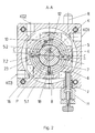
- the switching device according to the invention for safety shut-off valves operating without auxiliary energy and auxiliary gas essentially consists of a housing 1 provided with a base 2 and cover 3 , which is coupled to the safety shut-off valve (not shown ) via the flange 11 fastened to the base 2 by screwing.
- the flap shaft K has a driver 12, which extends in the longitudinal direction LR of the shaft K and is received by a groove 5.2 machined on the inner circumferential surface of the shaft K when the shaft K is axially inserted into the bore 5.1 of the locking bush 5 , so that the locking bush 5 is coaxial to the shaft K and the locking bush 5 is non-rotatable and positive on the shaft K.
- the rotating with the shaft K locking bush 5 is supported in a floatingbuild- at the bottom 2 of the housing 1 rigidly mounted slotted cylinder 6 in turn -As Fig. 1 to 3.
- the locking bush 5 is supported on the one hand by means of a bearing 13 on the base 2 and a bearing 14 on the locking bush 5 .
- the slot cylinder 6 holds axially parallel in its diametrically located to the shaft axis WA recesses 15 roller-shaped locking elements 23 which are incorporated in the outer jacket 16 of the locking sleeve 5 recesses 5.3 and 5.4 when the applied torque locks the valve shaft K.
- the slot cylinder 6 is surrounded by a hollow cylindrical bearing 9 , in which a sleeve-shaped cage 7 is held axially parallel to the shaft axis WA , which rotatably receives and guides diametrically opposite rolling elements 24 in recesses 7.1 and 7.2 .
- a hollow cylindrical abutment 4 which is supported with its outer jacket 17 on a roller bearing body 27 which is arranged on the bottom and cover side and is axially parallel to the flap shaft K , holds a roller-shaped abutment body 28 in recesses 19 .
- the rolling elements 24 in the cage 7 lie, as shown in FIGS. 2 and 3, in the locked state between the locking elements 23 and the roller-shaped abutment bodies 28 next to one another axially parallel and touch each other on their contact surfaces 23.1 or 23.2, 24.1 or 24.2 and 28.1 or 28.2 so that the radial forces caused by the rotation of the valve shaft K can be transmitted by a nearly ideal rolling of the contact surfaces on the abutment body 28th
- the center points M1, M2 and M3 of the locking elements 23, rolling elements 24 and abutment bodies 28 and the pivot point P of the shaft K are then arranged on a common axis CC .
- the contact lines K1 and K2 are then adjusted or adjusted about the axis CC in a positive or negative direction.
- Slot cylinder 6 and cage 7 are flexibly connected by a spring 10 under tension.
- the position of the cage 7 can be adjusted by means of a threaded pin 18 and adjusting nut 8 .
- the form spring 10 is fixed at one end in an opening 21 machined tangentially to the outer jacket 20 of the slot cylinder 6 and at the other end in a recess 22 of the cage 7 , so that the spring force of the form spring 10 causes the cage 7 tangentially in the direction of the slot cylinder 7 into its fixed position is withdrawn.
- the position of the cage 7 can be adjusted in a positive or negative direction in accordance with the switching forces required for the applied torques with respect to the axis of rotation WA of the shaft K.
- Fig. 4 shows the variant of a return of the cage 7 by means of magnets 25 , for example permanent magnets.
- the position of the abutment 4 with its abutment bodies 28 can be adjusted accordingly with a reset R or the manual release H (FIG. 2), which also contains an adjusting screw J.
- the applied torque of the flap shaft is absorbed by the K, in the recesses 5.3 and 5.4 inset locking elements 23rd
- the acting radial forces are transmitted via the corresponding contact surfaces of the rolling elements 24 to the contact surfaces 28.1 and 28.2 of the abutment body 28 .
- the center points M1, M2 and M3 are no longer on the common axis CC.
- the rolling bodies 24 roll on the respective abutment body 28 , since the diameter D3 of the abutment body 28 is smaller than the diameter D2 of the rolling body 24 .
- the diameters D1 of the locking elements 23 and the diameters D2 of the rolling elements 24 are selected to be approximately the same.
- a roller-shaped abutment body 28 it is also possible, as shown in FIGS. 5 and 6, to use strip-shaped bars 26 with correspondingly shaped contact surfaces without departing from the invention.
- Fig. 7 shows the switching device according to the invention in the unlocked state.
- FIG. 8 the execution of a switching device according to the invention is shown with a left-handed valve shaft K. It is only necessary to detach the flange 11 from the base 2 and fasten it to the cover 3 accordingly.
- the flap shaft K is inserted and fastened as previously described in the locking bush 5 .
- valve shaft K is reached again by means of a actuator not shown again in the Brought open position.
- the invention Switching device locks the flap shaft K automatically and the safety shut-off valve is ready.
Landscapes
- Engineering & Computer Science (AREA)
- General Engineering & Computer Science (AREA)
- Mechanical Engineering (AREA)
- Preventing Unauthorised Actuation Of Valves (AREA)
- Mechanically-Actuated Valves (AREA)
- Safety Valves (AREA)
Applications Claiming Priority (2)
| Application Number | Priority Date | Filing Date | Title |
|---|---|---|---|
| DE2002131904 DE10231904C1 (de) | 2002-07-09 | 2002-07-09 | Schaltvorrichtung für ein ohne Hilfsenergie arbeitendes Sicherheitsabsperrventil |
| DE10231904 | 2002-07-09 |
Publications (2)
| Publication Number | Publication Date |
|---|---|
| EP1380782A2 true EP1380782A2 (fr) | 2004-01-14 |
| EP1380782A3 EP1380782A3 (fr) | 2004-03-24 |
Family
ID=29265407
Family Applications (1)
| Application Number | Title | Priority Date | Filing Date |
|---|---|---|---|
| EP03090206A Withdrawn EP1380782A3 (fr) | 2002-07-09 | 2003-07-08 | Dispositif de commutation d'une soupape d'arrêt de securité commandée sans énergie auxiliaire |
Country Status (2)
| Country | Link |
|---|---|
| EP (1) | EP1380782A3 (fr) |
| DE (1) | DE10231904C1 (fr) |
Families Citing this family (4)
| Publication number | Priority date | Publication date | Assignee | Title |
|---|---|---|---|---|
| DE102007012292B8 (de) * | 2007-03-08 | 2008-10-02 | Rmg-Gaselan Regel + Messtechnik Gmbh | Kontrollgerät mit Schaltfunktion für ohne Hilfsenergie und Hilfsgas arbeitende Sicherheitsabsperrventile verschiedener Baugrößen |
| EP2587057B1 (fr) | 2011-10-28 | 2016-04-13 | Arquimea Ingenieria, S.L. | Dispositif actionneur linéaire |
| EP2902626B1 (fr) * | 2014-01-30 | 2016-07-27 | Arquimea Ingenieria S.L. | dispositif d'actionnement linéaire |
| CN105626878B (zh) * | 2016-03-28 | 2018-11-02 | 吴忠仪表有限责任公司 | 天然气调压撬用安全切断阀 |
Citations (3)
| Publication number | Priority date | Publication date | Assignee | Title |
|---|---|---|---|---|
| DE2303715A1 (de) | 1973-01-26 | 1974-08-01 | Regel Und Messtechnik Gmbh Reg | Sicherheits-absperrventil |
| DD152178A1 (de) | 1980-07-22 | 1981-11-18 | Helfried Uhlig | Ohne hilfsenergie und hilfsgas arbeitendes schnellschlussventil |
| DD206196A1 (de) | 1981-08-31 | 1984-01-18 | Fuerstenwalde Chem Tankanlagen | Ohne hilfsenergie und hilfsgas arbeitendes schnellschlussventil |
Family Cites Families (4)
| Publication number | Priority date | Publication date | Assignee | Title |
|---|---|---|---|---|
| DE1007587B (de) * | 1955-11-15 | 1957-05-02 | Kromschroeder Ag G | Handbetaetigtes Schnellschlussventil |
| DE3938216C1 (fr) * | 1989-11-17 | 1991-04-11 | Regel + Messtechnik Gmbh Regler- Und Anlagenbau Fuer Gas-Druckregelung, 3500 Kassel, De | |
| DE4300310A1 (de) * | 1993-01-08 | 1994-07-14 | Staiger Steuerungstech | Ventil |
| DE29506254U1 (de) * | 1995-04-07 | 1995-06-22 | RMG - Gaselan Regel + Meßtechnik GmbH, 15517 Fürstenwalde | Sicherheitsabsperrventil |
-
2002
- 2002-07-09 DE DE2002131904 patent/DE10231904C1/de not_active Expired - Fee Related
-
2003
- 2003-07-08 EP EP03090206A patent/EP1380782A3/fr not_active Withdrawn
Patent Citations (3)
| Publication number | Priority date | Publication date | Assignee | Title |
|---|---|---|---|---|
| DE2303715A1 (de) | 1973-01-26 | 1974-08-01 | Regel Und Messtechnik Gmbh Reg | Sicherheits-absperrventil |
| DD152178A1 (de) | 1980-07-22 | 1981-11-18 | Helfried Uhlig | Ohne hilfsenergie und hilfsgas arbeitendes schnellschlussventil |
| DD206196A1 (de) | 1981-08-31 | 1984-01-18 | Fuerstenwalde Chem Tankanlagen | Ohne hilfsenergie und hilfsgas arbeitendes schnellschlussventil |
Also Published As
| Publication number | Publication date |
|---|---|
| EP1380782A3 (fr) | 2004-03-24 |
| DE10231904C1 (de) | 2003-11-20 |
Similar Documents
| Publication | Publication Date | Title |
|---|---|---|
| DE4123349C1 (de) | Schrauber mit variabler Drehmomenteinstellung | |
| EP1688654B1 (fr) | Clapet à vide | |
| DE3611325C2 (fr) | ||
| CH663261A5 (de) | Schiebeventil. | |
| EP2529136B1 (fr) | Robinet d'arrêt pour le domaine des installations de second oeuvre | |
| EP0816730B1 (fr) | Dispositif de limitation de la précontrainte d'un ressort de réglage | |
| DE10231904C1 (de) | Schaltvorrichtung für ein ohne Hilfsenergie arbeitendes Sicherheitsabsperrventil | |
| EP0622574A2 (fr) | Dispositif de commande d'une pièce rotative d'obturation d'une soupape | |
| DE102007015212B4 (de) | Kompakt-Kombizylinder mit manueller Lösevorrichtung | |
| EP0155987B1 (fr) | Outil de rotation et de réglage pour pièces à symétrie axiale, en particulier pour bancs de direction de véhicule | |
| DE10203384A1 (de) | Servolenksystem | |
| EP1258321B1 (fr) | Tournevis motorisé avec embrayage limitateur de couple | |
| DE3142799C2 (de) | Mechanisch betätigte Gleitsattel-Scheibenbremse | |
| DE102012203874A1 (de) | Armatur | |
| DE2953734C1 (de) | Einrichtung zum Festziehen von Grobgewindeverbindungen | |
| DE102007012292B3 (de) | Kontrollgerät mit Schaltfunktion für ohne Hilfsenergie und Hilfsgas arbeitende Sicherheitsabsperrventile verschiedener Baugrößen | |
| EP0697268A1 (fr) | Dispositif de verrouillage reversible pour une poignée de réglage tournable | |
| EP3927997B1 (fr) | Entraînement à vis à billes avec dispositif d'antirotation | |
| DE1783026B2 (de) | Kraftbetätigte Rohrzange | |
| EP1260322B1 (fr) | Clef motorisée à tête angulaire | |
| EP0853991A1 (fr) | Tête de roulage radial | |
| DE10234371A1 (de) | Blockierbare Feststellvorrichtung | |
| DE19921213A1 (de) | Feststellvorrichtung für einen Türflügel | |
| DE102019121183A1 (de) | Sicherheitskupplung | |
| DE2011011B2 (de) | Schnellschlussventil mit einer kugelrasteinrichtung |
Legal Events
| Date | Code | Title | Description |
|---|---|---|---|
| PUAI | Public reference made under article 153(3) epc to a published international application that has entered the european phase |
Free format text: ORIGINAL CODE: 0009012 |
|
| AK | Designated contracting states |
Kind code of ref document: A2 Designated state(s): AT BE BG CH CY CZ DE DK EE ES FI FR GB GR HU IE IT LI LU MC NL PT RO SE SI SK TR |
|
| AX | Request for extension of the european patent |
Extension state: AL LT LV MK |
|
| PUAL | Search report despatched |
Free format text: ORIGINAL CODE: 0009013 |
|
| AK | Designated contracting states |
Kind code of ref document: A3 Designated state(s): AT BE BG CH CY CZ DE DK EE ES FI FR GB GR HU IE IT LI LU MC NL PT RO SE SI SK TR |
|
| AX | Request for extension of the european patent |
Extension state: AL LT LV MK |
|
| AKX | Designation fees paid |
Designated state(s): AT BE BG CH CY CZ DE DK EE ES FI FR GB GR HU IE IT LI LU MC NL PT RO SE SI SK TR |
|
| AXX | Extension fees paid |
Extension state: LV Payment date: 20030708 Extension state: LT Payment date: 20030708 |
|
| STAA | Information on the status of an ep patent application or granted ep patent |
Free format text: STATUS: THE APPLICATION IS DEEMED TO BE WITHDRAWN |
|
| 18D | Application deemed to be withdrawn |
Effective date: 20040925 |