EP1380792A1 - Vorrichtung zum Schutz eines Rippenschlauches - Google Patents
Vorrichtung zum Schutz eines Rippenschlauches Download PDFInfo
- Publication number
- EP1380792A1 EP1380792A1 EP03014989A EP03014989A EP1380792A1 EP 1380792 A1 EP1380792 A1 EP 1380792A1 EP 03014989 A EP03014989 A EP 03014989A EP 03014989 A EP03014989 A EP 03014989A EP 1380792 A1 EP1380792 A1 EP 1380792A1
- Authority
- EP
- European Patent Office
- Prior art keywords
- partial rings
- partial
- rings
- ribbed
- ribbed tube
- Prior art date
- Legal status (The legal status is an assumption and is not a legal conclusion. Google has not performed a legal analysis and makes no representation as to the accuracy of the status listed.)
- Granted
Links
- 230000000295 complement effect Effects 0.000 claims description 8
- 238000002310 reflectometry Methods 0.000 claims description 3
- 230000001012 protector Effects 0.000 description 6
- 230000001681 protective effect Effects 0.000 description 3
- 238000004026 adhesive bonding Methods 0.000 description 1
- 238000005452 bending Methods 0.000 description 1
- 230000015572 biosynthetic process Effects 0.000 description 1
- 230000006378 damage Effects 0.000 description 1
- 238000005755 formation reaction Methods 0.000 description 1
- 210000001331 nose Anatomy 0.000 description 1
- 230000003068 static effect Effects 0.000 description 1
- 238000003466 welding Methods 0.000 description 1
Images


Classifications
-
- F—MECHANICAL ENGINEERING; LIGHTING; HEATING; WEAPONS; BLASTING
- F16—ENGINEERING ELEMENTS AND UNITS; GENERAL MEASURES FOR PRODUCING AND MAINTAINING EFFECTIVE FUNCTIONING OF MACHINES OR INSTALLATIONS; THERMAL INSULATION IN GENERAL
- F16L—PIPES; JOINTS OR FITTINGS FOR PIPES; SUPPORTS FOR PIPES, CABLES OR PROTECTIVE TUBING; MEANS FOR THERMAL INSULATION IN GENERAL
- F16L11/00—Hoses, i.e. flexible pipes
- F16L11/04—Hoses, i.e. flexible pipes made of rubber or flexible plastics
- F16L11/11—Hoses, i.e. flexible pipes made of rubber or flexible plastics with corrugated wall
-
- F—MECHANICAL ENGINEERING; LIGHTING; HEATING; WEAPONS; BLASTING
- F16—ENGINEERING ELEMENTS AND UNITS; GENERAL MEASURES FOR PRODUCING AND MAINTAINING EFFECTIVE FUNCTIONING OF MACHINES OR INSTALLATIONS; THERMAL INSULATION IN GENERAL
- F16L—PIPES; JOINTS OR FITTINGS FOR PIPES; SUPPORTS FOR PIPES, CABLES OR PROTECTIVE TUBING; MEANS FOR THERMAL INSULATION IN GENERAL
- F16L11/00—Hoses, i.e. flexible pipes
- F16L11/14—Hoses, i.e. flexible pipes made of rigid material, e.g. metal or hard plastics
- F16L11/15—Hoses, i.e. flexible pipes made of rigid material, e.g. metal or hard plastics corrugated
-
- F—MECHANICAL ENGINEERING; LIGHTING; HEATING; WEAPONS; BLASTING
- F16—ENGINEERING ELEMENTS AND UNITS; GENERAL MEASURES FOR PRODUCING AND MAINTAINING EFFECTIVE FUNCTIONING OF MACHINES OR INSTALLATIONS; THERMAL INSULATION IN GENERAL
- F16L—PIPES; JOINTS OR FITTINGS FOR PIPES; SUPPORTS FOR PIPES, CABLES OR PROTECTIVE TUBING; MEANS FOR THERMAL INSULATION IN GENERAL
- F16L57/00—Protection of pipes or objects of similar shape against external or internal damage or wear
Definitions
- the invention relates to a device for protecting a Ribbed hose against wear.
- Such rib hoses are used as protective hoses for Energy supply lines for tools, machines and used in particular robots.
- the protective tubes are designed as rib hoses to provide high flexibility to enable, in particular, a robot in the hand area or immediately before the hand of the robot required is because the hand makes complex movements around three axes (Robot axes A4 to A6) can perform. It exists the risk that such a protective hose on parts of Robot rubs. To protect the hose this is with Protectors provided in the form of wear rings, which extend longitudinally over several ribs. she have this several réellerippen- and grooves, with which put them on several ribs of the ribbed tube.
- Such protectors increase the mobility of the finned tube, where such a protector sits, strongly limited. This causes in areas where no protector is given, an even stronger bend and thus load on the ribbed tube is given. Also is determined by the height of the protectors, which are 20 to 30 mm may be, in addition, a bend of the finned tube caused by the resulting distance to the robot part. Such protectors are therefore in critical Areas often omitted, increasing the risk of increased Wear of the ribbed tube in these areas given is.
- the invention is therefore based on the object, a device to provide protection for a ribbed tube, the while avoiding the aforementioned disadvantages despite a good Protection of the ribbed hose against wear continue high mobility of the same even in the protected Area allows.
- the invention is also the task to create a protected ribbed tube, the So even low wear is exposed, nevertheless but maintains high mobility.
- an said device for protecting a ribbed tube solved against wear which is marked by a ring part with at least two at their end faces connectable one-piece part rings on its inside a to the outside of a rib of the Ribbed hose adapted to have annular groove.
- the invention is based on the object, an inventive To design device such that it on a single rib of a ribbed tube is seated. hereby the bendability of the ribbed tube is in no Way, yet protect it against Wear guaranteed. By this configuration can also be achieved that the height of the protection device significantly reduced and brought in the millimeter range becomes. This causes static bends, as they exist in the prior art to a considerable extent are, reduced or excluded.
- the former means that on every third, everyone second or even every adjacent rib in a certain Area a corresponding protection device according to the invention touches down, i. between two sitting on ribs Protection devices not more than two unprotected Ribs or just one unprotected rib (or none) are present or is.
- the annular groove trapezoidal Cross-section has, in particular, the annular groove through two spaced apart in the axial direction is limited parallel to each other ring lands.
- the outside of the guards or the ring part or the partial rings can be formed in various ways be. It is a rectangular or likewise Trapezoidal cross-section possible.
- the partial rings on their outside have a semi-circular cross-section.
- An extremely preferred embodiment provides that the partial rings are each formed identically. This makes it possible, even two or more partial rings to produce only with a tool.
- connection of the partial rings on their front sides can also be done in different ways. So can be provided in a preferred manner that the partial rings are positively connected to each other or that the partial rings are connected by positive locking. In the first mentioned case, a preferred embodiment provides before that the partial rings on the front sides with each other are glued. But also a welding of the end areas the partial rings is possible. In a positive connection may be provided in particular that the partial rings At their end faces complementary undercuts , wherein the complementary undercuts preferably are formed such that the undercuts formed by a transverse groove cross hook part or are.
- the hook parts can do so be designed that at least one hook on one end face a partial ring radially from outside to inside and complementary Hook is directed radially from the inside out.
- This training also applies in the event that the partial rings are not identical.
- two partial rings that is HalVE can be provided that on a partial ring the both end faces from outside to inside protruding hooks, on another partial ring provided from inside to outside protruding hooks are; but in this case one is for each subring own tool required.
- in each part ring at one end an from outside to inside protruding hook and at the other end one from the inside out has protruding complementary hooks is only Tool required because such part rings formed identical could be.
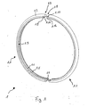
- the device according to the invention consists 1 for protecting a ribbed tube 2 (FIGS 6) in the illustrated embodiment of two partial rings 1.1 in the form of half rings. It can also consist of several partial rings 1.1, for example, consist of three partial rings.
- the partial rings 1.1 are each formed identically.
- the Partial rings 1.1 have a semicircular in cross section Outer contour 1.2 on, with other outer contours, in particular Also convex outer contours are possible. On their inside they have one over their longitudinal extent in the circumferential direction groove 1.3.
- the groove has 1.3 a trapezoidal cross section and extends from their bottom area 1.4 inwards. It gets through two lateral ring webs 1.5, 1.6 limited.
- the partial rings can be formed completely flat on their front sides. You can then by a non-positive connection, as by Gluing together to be sure To get seat on the rib of a ribbed tube 2.
- the Form gleich field 1.7 has For this purpose, an inwardly open groove 1.9, which by one of the outside of the groove 1.9 over and behind Hook 1.10 is formed.
- the form-locking education 1.8 is designed to be complementary and accordingly has a radial outwardly open groove 1.11 made by a she formed over and behind hooks 1.12.
- to Connection of the two partial rings 1.1 are the hook or Noses 1.10, 1.12 in the circumferential direction against and over each other pushed until they are each in the opposite groove engage. This is a safe and reliable form-fitting connection of the two partial rings 1.1 around a rib created a rib tube.
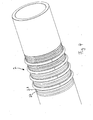
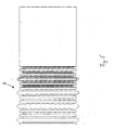
- FIGS. 4 to 6 show sections of a ribbed tube, the same with devices according to the invention for the protection thereof are provided.
- a provided with such devices Ribbed tube is also an object of the invention.
- the Ribbed tube has several longitudinally side by side arranged over the circumference of the finned tube 2 extending ribs 2.1 on, between which annular grooves 2.2 are formed. This gives the ribbed tube 2 a high flexibility.
- device according to the invention to protect such a ribbed tube 2 sits in each case, as already stated, on a circumferential rib 2.1 such Device held by the rib laterally - i. in Axially surrounding ring webs 1.5, 1.6 in the axial direction - form-fitting on.
Landscapes
- Engineering & Computer Science (AREA)
- General Engineering & Computer Science (AREA)
- Mechanical Engineering (AREA)
- Protection Of Pipes Against Damage, Friction, And Corrosion (AREA)
Abstract
Description
- Fig. 1
- eine bevorzugte Ausführungsform einer erfindungsgemäßen Vorrichtung zum Schutz eines Rippenschlauches vor Zusammensetzen der Teilringe;
- Fig. 2
- eine vergrößerte Darstellung des Verbindungsbereichs der beiden Teilringe der Fig. 1;
- Fig. 3
- die erfindungsgemäße Vorrichtung der Fig. 1 im zusammengesetzten Zustand;
- Fig. 4
- einen Rippenschlauch mit erfindungsgemäßen Vorrichtungen zum Schutz desselben in perspektivischer Darstellung;
- Fig. 5
- einen Abschnitt eines Rippenschlauches mit erfindungsgemäßen Vorrichtungen zum Schutz desselben in Seitenansicht, teilweise geschnitten; und
- Fig. 6
- eine vergrößerte Ausschnittsdarstellung des Gegenstandes der Fig. 5.
- 1
- erfindungsgemäße Vorrichtung
- 1.1
- Teilringe
- 1.2
- Außenkontur
- 1.3
- Nut
- 1.4
- Bodenbereich
- 1.5
- Ringsteg
- 1.6
- Ringsteg
- 1.7
- Formschlussausbildung
- 1.8
- Formschlussausbildung
- 1.9
- Nut
- 1.10
- Haken
- 1.11
- Nut
- 1.12
- Haken
- 2
- Rippenschlauch
- 2.1
- Rippen
- 2.2
- Ringnut
Claims (16)
- Vorrichtung zum Schutz eines Rippenschlauches gegen Verschleiß, gekennzeichnet durch ein Ringteil (1) mit mindestens zwei an ihren Stirnseiten miteinander verbindbaren einstückigen Teilringen (1.1), die auf ihrer Innenseite eine an die Außenseite einer Rippe des Rippenschlauches angepasste Ringnut (1.3) aufweisen.
- Vorrichtung nach Anspruch 1, dadurch gekennzeichnet, dass die Ringnut (1.3) trapezförmigen Querschnitt hat.
- Vorrichtung nach Anspruch 1 oder 2, dadurch gekennzeichnet, dass die Ringnut durch zwei in Axialrichtung mit Abstand zueinander angeordnete parallel zueinander verlaufende Ringstege (1.5, 1.6) begrenzt ist.
- Vorrichtung nach einem der vorangehenden Ansprüche, dadurch gekennzeichnet, dass die Teilringe (1.1) auf ihrer Außenseite einen halbkreisförmigen Querschnitt aufweisen.
- Vorrichtung nach einem der vorangehenden Ansprüche, dadurch gekennzeichnet, dass die Teilringe jeweils identisch ausgebildet sind.
- Vorrichtung nach einem der vorangehenden Ansprüche, dadurch gekennzeichnet, dass die Teilringe kraftschlüssig miteinander verbunden sind.
- Vorrichtung nach einem der vorangehenden Ansprüche, dadurch gekennzeichnet, dass die Teilringe (1.1) an den Stirnseiten miteinander verklebt sind.
- Vorrichtung nach einem der Ansprüche 1 bis 5, dadurch gekennzeichnet, dass die Teilringe durch Formschluss miteinander verbunden sind.
- Vorrichtung nach einem der Ansprüche 1 bis 5, 8, dadurch gekennzeichnet, dass die Teilringe (1.1) an ihren Stirnseiten komplementäre Hinterschneidungen aufweisen.
- Vorrichtung nach Anspruch 9, dadurch gekennzeichnet, dass die Hinterschneidungen durch ein eine Quernut (1.9 bzw. 1.11) übergreifendes Hakenteil (1.10) bzw. (1.12) gebildet sind.
- Vorrichtung nach Anspruch 10, dadurch gekennzeichnet, dass zumindest ein Haken (1.10) an einer Stirnseite eines Teilrings (1.1) radial von außen nach innen und ein komplementärer Haken (1.12) radial von innen nach außen gerichtet ist.
- Vorrichtung nach einem der vorangehenden Ansprüche, dadurch gekennzeichnet, dass Teilringe in Radialrichtung zumindest zweischichtig mit Schichten unterschiedlichen Reflektionsvermögens ausgebildet sind.
- Vorrichtung nach Anspruch 12, dadurch gekennzeichnet, dass die Schichten der Teilringe unterschiedliches Reflektionsvermögen in verschiedenen Wellenbereichen aufweisen.
- Rippenschlauch, gekennzeichnet durch zumindest eine Vorrichtung nach einem der vorangehenden Ansprüche.
- Rippenschlauch nach Anspruch 14, dadurch gekennzeichnet, dass in einem Teilbereich des Rippenschlauches jede dritte Rippe (oder weniger) mit einer Vorrichtung gemäß einem der Ansprüche 1 bis 14 versehen ist.
- Vorrichtung nach Anspruch 14 oder 15, dadurch gekennzeichnet, dass in einem Teilbereich des Rippenschlauches mindestens drei Vorrichtungen nach einem der Ansprüche 1 bis 14 in Axialrichtung hintereinander angeordnet sind.
Applications Claiming Priority (2)
| Application Number | Priority Date | Filing Date | Title |
|---|---|---|---|
| DE20211396U DE20211396U1 (de) | 2002-07-11 | 2002-07-11 | Vorrichtung zum Schutz eines Rippenschlauchs |
| DE20211396U | 2002-07-11 |
Publications (2)
| Publication Number | Publication Date |
|---|---|
| EP1380792A1 true EP1380792A1 (de) | 2004-01-14 |
| EP1380792B1 EP1380792B1 (de) | 2006-06-21 |
Family
ID=27763048
Family Applications (1)
| Application Number | Title | Priority Date | Filing Date |
|---|---|---|---|
| EP20030014989 Expired - Lifetime EP1380792B1 (de) | 2002-07-11 | 2003-07-02 | Vorrichtung zum Schutz eines Rippenschlauches |
Country Status (2)
| Country | Link |
|---|---|
| EP (1) | EP1380792B1 (de) |
| DE (2) | DE20211396U1 (de) |
Citations (7)
| Publication number | Priority date | Publication date | Assignee | Title |
|---|---|---|---|---|
| CH255186A (fr) * | 1938-11-25 | 1948-06-15 | Prod Du Lynx Jaune | Tube flexible. |
| US3464722A (en) * | 1968-04-19 | 1969-09-02 | Sam Larkin | Pipe coupling having segmented clamping means |
| US3797836A (en) * | 1971-09-07 | 1974-03-19 | Pressure Science Inc | Sealing ring |
| JPS5498450A (en) * | 1978-01-09 | 1979-08-03 | Esu Rafuaatei Shiniaa Geerii | Coupling member |
| US5690146A (en) * | 1996-08-20 | 1997-11-25 | Aeroquip Corporation | Hose and method for wear detection |
| DE29814418U1 (de) * | 1998-08-11 | 1998-10-08 | Kuka Roboter GmbH, 86165 Augsburg | Verschleißring für einen Kabelführungsschlauch eines Roboters |
| DE20100947U1 (de) * | 2001-01-19 | 2001-05-03 | Kuka Roboter GmbH, 86165 Augsburg | Verschleißring |
-
2002
- 2002-07-11 DE DE20211396U patent/DE20211396U1/de not_active Expired - Lifetime
-
2003
- 2003-07-02 DE DE50303909T patent/DE50303909D1/de not_active Expired - Lifetime
- 2003-07-02 EP EP20030014989 patent/EP1380792B1/de not_active Expired - Lifetime
Patent Citations (7)
| Publication number | Priority date | Publication date | Assignee | Title |
|---|---|---|---|---|
| CH255186A (fr) * | 1938-11-25 | 1948-06-15 | Prod Du Lynx Jaune | Tube flexible. |
| US3464722A (en) * | 1968-04-19 | 1969-09-02 | Sam Larkin | Pipe coupling having segmented clamping means |
| US3797836A (en) * | 1971-09-07 | 1974-03-19 | Pressure Science Inc | Sealing ring |
| JPS5498450A (en) * | 1978-01-09 | 1979-08-03 | Esu Rafuaatei Shiniaa Geerii | Coupling member |
| US5690146A (en) * | 1996-08-20 | 1997-11-25 | Aeroquip Corporation | Hose and method for wear detection |
| DE29814418U1 (de) * | 1998-08-11 | 1998-10-08 | Kuka Roboter GmbH, 86165 Augsburg | Verschleißring für einen Kabelführungsschlauch eines Roboters |
| DE20100947U1 (de) * | 2001-01-19 | 2001-05-03 | Kuka Roboter GmbH, 86165 Augsburg | Verschleißring |
Also Published As
| Publication number | Publication date |
|---|---|
| EP1380792B1 (de) | 2006-06-21 |
| DE50303909D1 (de) | 2006-08-03 |
| DE20211396U1 (de) | 2003-08-14 |
Similar Documents
| Publication | Publication Date | Title |
|---|---|---|
| EP2839183B1 (de) | Energieführungskette mit rollen | |
| EP3115640B1 (de) | Gurt oder gurtsegment | |
| EP0459104B1 (de) | Flyerkette | |
| DE3201840A1 (de) | Kettenflachschloss | |
| DE2914800A1 (de) | Gelenkzapfenanordnung und kettenanordnung mit einer derartigen gelenkzapfenanordnung | |
| DE10082339B4 (de) | Antriebsgelenk | |
| DE2644992C2 (de) | ||
| EP1380792B1 (de) | Vorrichtung zum Schutz eines Rippenschlauches | |
| DE4126940C2 (de) | Vorrichtung und Verfahren zum Transport und der Montage für Wälzkörperkränze | |
| EP1488885B1 (de) | Gliederbahn, insbesondere für Werkzeugmaschinen | |
| EP3140553A1 (de) | Befestigungsmittel, insbesondere für bälge, mit einem männlichen und einem weiblichen endabschnitt | |
| EP3140554B1 (de) | Befestigungsmittel, insbesondere für bälge, mit einem inneren hinterschneidungsbereich | |
| DE102023203391A1 (de) | Zahnscheibe | |
| DE4136686C2 (de) | Kupplungsmuffe | |
| EP2781428A2 (de) | Transportkarre mit schwenkbarer Handgriffanordnung | |
| EP1146238A2 (de) | Ringlamelle für flexible Wellenkupplungen | |
| DE3434491A1 (de) | Rohr fuer einen abgaskanal | |
| DE202007003592U1 (de) | Flexibles Leitungselement | |
| DE102016211917A1 (de) | Wälzlagerkäfig oder Wälzlagerkäfigsegment | |
| DE1780729C3 (de) | Gleitschutz- bzw. Reifenschutzkette | |
| DE2949126A1 (de) | Distanzhalter fuer rohre | |
| DE4420203C2 (de) | Kettenschloß für Rundgliederketten | |
| EP1355073A1 (de) | Gelenkgabel und Kreuzgelenk mit einer solchen | |
| DE3724540C1 (en) | Horizontal link | |
| EP3031704A1 (de) | Gleiskette |
Legal Events
| Date | Code | Title | Description |
|---|---|---|---|
| PUAI | Public reference made under article 153(3) epc to a published international application that has entered the european phase |
Free format text: ORIGINAL CODE: 0009012 |
|
| AK | Designated contracting states |
Kind code of ref document: A1 Designated state(s): AT BE BG CH CY CZ DE DK EE ES FI FR GB GR HU IE IT LI LU MC NL PT RO SE SI SK TR |
|
| AX | Request for extension of the european patent |
Extension state: AL LT LV MK |
|
| 17P | Request for examination filed |
Effective date: 20031203 |
|
| AKX | Designation fees paid |
Designated state(s): DE FR GB IT SE |
|
| 17Q | First examination report despatched |
Effective date: 20050414 |
|
| GRAP | Despatch of communication of intention to grant a patent |
Free format text: ORIGINAL CODE: EPIDOSNIGR1 |
|
| GRAS | Grant fee paid |
Free format text: ORIGINAL CODE: EPIDOSNIGR3 |
|
| GRAA | (expected) grant |
Free format text: ORIGINAL CODE: 0009210 |
|
| AK | Designated contracting states |
Kind code of ref document: B1 Designated state(s): DE FR GB IT SE |
|
| PG25 | Lapsed in a contracting state [announced via postgrant information from national office to epo] |
Ref country code: GB Free format text: LAPSE BECAUSE OF FAILURE TO SUBMIT A TRANSLATION OF THE DESCRIPTION OR TO PAY THE FEE WITHIN THE PRESCRIBED TIME-LIMIT Effective date: 20060621 |
|
| REG | Reference to a national code |
Ref country code: GB Ref legal event code: FG4D Free format text: NOT ENGLISH |
|
| REF | Corresponds to: |
Ref document number: 50303909 Country of ref document: DE Date of ref document: 20060803 Kind code of ref document: P |
|
| REG | Reference to a national code |
Ref country code: SE Ref legal event code: TRGR |
|
| GBV | Gb: ep patent (uk) treated as always having been void in accordance with gb section 77(7)/1977 [no translation filed] |
Effective date: 20060621 |
|
| PLBE | No opposition filed within time limit |
Free format text: ORIGINAL CODE: 0009261 |
|
| STAA | Information on the status of an ep patent application or granted ep patent |
Free format text: STATUS: NO OPPOSITION FILED WITHIN TIME LIMIT |
|
| EN | Fr: translation not filed | ||
| 26N | No opposition filed |
Effective date: 20070322 |
|
| PG25 | Lapsed in a contracting state [announced via postgrant information from national office to epo] |
Ref country code: FR Free format text: LAPSE BECAUSE OF FAILURE TO SUBMIT A TRANSLATION OF THE DESCRIPTION OR TO PAY THE FEE WITHIN THE PRESCRIBED TIME-LIMIT Effective date: 20070504 |
|
| PG25 | Lapsed in a contracting state [announced via postgrant information from national office to epo] |
Ref country code: FR Free format text: LAPSE BECAUSE OF FAILURE TO SUBMIT A TRANSLATION OF THE DESCRIPTION OR TO PAY THE FEE WITHIN THE PRESCRIBED TIME-LIMIT Effective date: 20060731 |
|
| PG25 | Lapsed in a contracting state [announced via postgrant information from national office to epo] |
Ref country code: FR Free format text: LAPSE BECAUSE OF FAILURE TO SUBMIT A TRANSLATION OF THE DESCRIPTION OR TO PAY THE FEE WITHIN THE PRESCRIBED TIME-LIMIT Effective date: 20060621 |
|
| REG | Reference to a national code |
Ref country code: DE Ref legal event code: R082 Ref document number: 50303909 Country of ref document: DE |
|
| REG | Reference to a national code |
Ref country code: DE Ref legal event code: R081 Ref document number: 50303909 Country of ref document: DE Owner name: KUKA DEUTSCHLAND GMBH, DE Free format text: FORMER OWNER: KUKA ROBOTER GMBH, 86165 AUGSBURG, DE |
|
| PGFP | Annual fee paid to national office [announced via postgrant information from national office to epo] |
Ref country code: IT Payment date: 20190719 Year of fee payment: 17 Ref country code: SE Payment date: 20190710 Year of fee payment: 17 Ref country code: DE Payment date: 20190618 Year of fee payment: 17 |
|
| REG | Reference to a national code |
Ref country code: DE Ref legal event code: R119 Ref document number: 50303909 Country of ref document: DE |
|
| REG | Reference to a national code |
Ref country code: SE Ref legal event code: EUG |
|
| PG25 | Lapsed in a contracting state [announced via postgrant information from national office to epo] |
Ref country code: DE Free format text: LAPSE BECAUSE OF NON-PAYMENT OF DUE FEES Effective date: 20210202 Ref country code: SE Free format text: LAPSE BECAUSE OF NON-PAYMENT OF DUE FEES Effective date: 20200703 |
|
| PG25 | Lapsed in a contracting state [announced via postgrant information from national office to epo] |
Ref country code: IT Free format text: LAPSE BECAUSE OF NON-PAYMENT OF DUE FEES Effective date: 20200702 |