EP1380792B1 - Dispositif de protection d'un tuyau ondulé - Google Patents
Dispositif de protection d'un tuyau ondulé Download PDFInfo
- Publication number
- EP1380792B1 EP1380792B1 EP20030014989 EP03014989A EP1380792B1 EP 1380792 B1 EP1380792 B1 EP 1380792B1 EP 20030014989 EP20030014989 EP 20030014989 EP 03014989 A EP03014989 A EP 03014989A EP 1380792 B1 EP1380792 B1 EP 1380792B1
- Authority
- EP
- European Patent Office
- Prior art keywords
- hose according
- partial
- partial rings
- hose
- rings
- Prior art date
- Legal status (The legal status is an assumption and is not a legal conclusion. Google has not performed a legal analysis and makes no representation as to the accuracy of the status listed.)
- Expired - Lifetime
Links
- 238000002310 reflectometry Methods 0.000 claims description 4
- 230000000295 complement effect Effects 0.000 description 6
- 230000001681 protective effect Effects 0.000 description 6
- 230000001012 protector Effects 0.000 description 6
- 238000005452 bending Methods 0.000 description 4
- 230000015572 biosynthetic process Effects 0.000 description 3
- 238000005755 formation reaction Methods 0.000 description 3
- 230000001771 impaired effect Effects 0.000 description 2
- 238000004026 adhesive bonding Methods 0.000 description 1
- 230000006378 damage Effects 0.000 description 1
- 230000003068 static effect Effects 0.000 description 1
- 238000003466 welding Methods 0.000 description 1
Images


Classifications
-
- F—MECHANICAL ENGINEERING; LIGHTING; HEATING; WEAPONS; BLASTING
- F16—ENGINEERING ELEMENTS AND UNITS; GENERAL MEASURES FOR PRODUCING AND MAINTAINING EFFECTIVE FUNCTIONING OF MACHINES OR INSTALLATIONS; THERMAL INSULATION IN GENERAL
- F16L—PIPES; JOINTS OR FITTINGS FOR PIPES; SUPPORTS FOR PIPES, CABLES OR PROTECTIVE TUBING; MEANS FOR THERMAL INSULATION IN GENERAL
- F16L11/00—Hoses, i.e. flexible pipes
- F16L11/04—Hoses, i.e. flexible pipes made of rubber or flexible plastics
- F16L11/11—Hoses, i.e. flexible pipes made of rubber or flexible plastics with corrugated wall
-
- F—MECHANICAL ENGINEERING; LIGHTING; HEATING; WEAPONS; BLASTING
- F16—ENGINEERING ELEMENTS AND UNITS; GENERAL MEASURES FOR PRODUCING AND MAINTAINING EFFECTIVE FUNCTIONING OF MACHINES OR INSTALLATIONS; THERMAL INSULATION IN GENERAL
- F16L—PIPES; JOINTS OR FITTINGS FOR PIPES; SUPPORTS FOR PIPES, CABLES OR PROTECTIVE TUBING; MEANS FOR THERMAL INSULATION IN GENERAL
- F16L11/00—Hoses, i.e. flexible pipes
- F16L11/14—Hoses, i.e. flexible pipes made of rigid material, e.g. metal or hard plastics
- F16L11/15—Hoses, i.e. flexible pipes made of rigid material, e.g. metal or hard plastics corrugated
-
- F—MECHANICAL ENGINEERING; LIGHTING; HEATING; WEAPONS; BLASTING
- F16—ENGINEERING ELEMENTS AND UNITS; GENERAL MEASURES FOR PRODUCING AND MAINTAINING EFFECTIVE FUNCTIONING OF MACHINES OR INSTALLATIONS; THERMAL INSULATION IN GENERAL
- F16L—PIPES; JOINTS OR FITTINGS FOR PIPES; SUPPORTS FOR PIPES, CABLES OR PROTECTIVE TUBING; MEANS FOR THERMAL INSULATION IN GENERAL
- F16L57/00—Protection of pipes or objects of similar shape against external or internal damage or wear
Definitions
- the invention relates to a ribbed hose according to the preamble of claim 1.
- Such finned tubes are used as protective hoses for energy supply lines in tools, machines and in particular robots.
- the protective hoses are designed as finned tubes in order to enable a high degree of flexibility, which is especially required in the case of a robot in the hand area or directly in front of the hand of the robot, since the hand can execute complex movements about three axes (robot axes A4 to A6). There is a risk that such a protective tube rubs on parts of the robot.
- protectors in the form of wear rings which extend in the longitudinal direction over a plurality of ribs. They have for this purpose a plurality of réellerippen- and grooves, with which they sit on several ribs of the fin tube.
- the invention is therefore an object of the invention to provide a device for protecting a ribbed tube, while avoiding the aforementioned disadvantages, despite a good Protection of the ribbed tube against wear allows a continued high mobility of the same even in the protected area.
- the invention is also based on the object to provide a protected ribbed tube, which is thus exposed to even low wear, but still maintains a high degree of flexibility.
- said object is achieved in a generic finned tube by the characterizing features of claim 1.
- the invention involves designing the protective device so that it rests on a single rib of a ribbed tube. As a result, the bending ability of the finned tube is impaired in any way, yet a same protection against wear guaranteed. By this configuration can also be achieved that the height of the protection device is substantially reduced and brought in the millimeter range. As a result, static-related bends, as they are present in the prior art to a considerable extent, reduced or excluded.
- the invention provides in a preferred embodiment that in a portion of the finned tube every third rib (or less) is provided with the device, in particular in a partial region of the finned tube at least three devices are arranged one behind the other in the axial direction.
- the first means that on each third, every second or even each adjacent rib in a certain area a corresponding protection device according to the invention touches, ie between two riders sitting on ribs no more than two unprotected ribs or just one unprotected rib (or none) are present or is.
- the annular groove has a trapezoidal cross-section, wherein in particular the annular groove is bounded by two axially spaced apart mutually parallel annular webs.
- the outside of the guards or the ring member or the partial rings may be formed in various ways. It is a rectangular or trapezoidal cross-section possible.
- the partial rings have a semicircular cross section on their outer side.
- the partial rings are each formed identically. This makes it possible to produce two or more sub-rings only with a tool.
- connection of the partial rings on their end faces can also be done in different ways.
- the partial rings are positively connected to each other or that the partial rings are connected by positive locking.
- a preferred embodiment provides that the partial rings are glued to one another at the end faces. But also a welding of the end portions of the partial rings is possible.
- the partial rings have complementary undercuts on their end faces, wherein the complementary undercuts are preferably formed such that the undercuts are formed by a transverse groove cross hook part or.
- the hook parts can be designed so that at least one hook is directed radially on a front side of a partial ring from outside to inside and complementary hooks from the inside to the outside.
- This training also applies to the case that the partial rings are not identical.
- provision can be made for the two end faces to be provided from outside to inside protruding hooks on a partial ring, and hooks projecting from the inside outwards on the other partial ring; In this case, however, a separate tool is required for each partial ring.
- each sub-ring has at one end a hook projecting from outside to inside and at the other end has a complementary hook projecting from the inside to the outside, only tools are required because such sub-rings can be identical.
- partial rings are formed in the radial direction at least two layers with layers of different reflectivity, in particular the layers of the partial rings different Have reflectivity in different wavelengths.
- the invention provides a finned tube with a device for protecting same against wear, which also ensures good protection of the wear while allowing the necessary mobility of the finned tube.
- the device 1 for protecting a ribbed tube 2 in the exemplary embodiment according to the invention consists of two partial rings 1.1 in the form of half rings. It can also consist of several partial rings 1.1, for example, three partial rings.
- the partial rings 1.1 are each formed identically.
- the partial rings 1.1 have a semicircular in cross-section outer contour 1.2, wherein also other outer contours, in particular convex outer contours are possible.
- the groove 1.3 has a trapezoidal cross-section and widens inwards from its bottom region 1.4. It is bounded by two lateral ring lands 1.5, 1.6.
- the partial rings can be formed completely flat on their front sides. They can then be connected to each other by a frictional connection, such as by gluing, so as to obtain a secure fit on the rib of a finned tube 2.
- the partial rings 1.1 have form-locking formations 1.7, 1.8 complementary to their end faces.
- the form-fit formation 1.7 has an inwardly open groove 1.9, which is formed by a hook 1.10 extending beyond the groove 1.9 and engaging behind it from the outside.
- the form-fitting formation 1.8 is designed to be complementary thereto and accordingly has a radially outwardly open groove 1.11, which is formed by an over-engaging and behind hook 1.12.
- the hooks or lugs 1.10, 1.12 in the circumferential direction against each other and pushed over each other until they engage in each case in the opposite groove. This creates a secure and reliable form-fit connection of the two partial rings 1.1 around a rib of a ribbed tube.
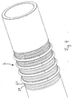
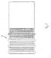
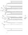
- Figs. 4 to 6 show sections of a fin tube according to the invention, which are provided with devices for the protection thereof.
- a provided with such devices ribbed hose is the subject of the invention.
- the ribbed tube has a plurality of longitudinally juxtaposed ribs 2. 1 extending over the circumference of the ribbed tube 2, between which annular grooves 2. 2 are formed. This gives the fin tube 2 a high flexibility.
- a circumferential rib 2.1 such a device held by the rib laterally - i.e. in the axial direction encompassing annular webs 1.5, 1.6 in the axial direction - positively on.
- every third rib Device 1 ie that between two devices not more than two unprotected ribs 2.1 of the fin tube 2 are provided, as shown in FIGS. 4 and 6.
- every second rib is provided with a device according to the invention, that is, there is only one unprotected rib between two devices.
- a ribbed tube according to the invention which is protected against wear by means of the device is thus created, which, despite this protection, has a high degree of flexibility even in the protected area.
Landscapes
- Engineering & Computer Science (AREA)
- General Engineering & Computer Science (AREA)
- Mechanical Engineering (AREA)
- Protection Of Pipes Against Damage, Friction, And Corrosion (AREA)
Claims (15)
- Tuyau annelé équipé d'au moins un dispositif de protection contre l'usure sous la forme d'au moins une pièce annulaire entourant le tuyau et comportant au moins deux anneaux partiels (1.1) d'une seule pièce reliables entre eux au niveau de leurs faces frontales, caractérisé en ce que l'au moins une pièce annulaire présente sur sa face interne une rainure annulaire (1.3) exactement adaptée à la face extérieure d'une saillie annulaire du tuyau annelé.
- Tuyau selon la revendication 1, caractérisé en ce que la rainure annulaire (1.3) présente une section trapézoïdale.
- Tuyau selon la revendication 1 ou 2, caractérisé en ce que la rainure annulaire est délimitée par deux nervures annulaires (1.5, 1.6) disposées à distance l'une de l'autre en direction axiale et s'étendant parallèles l'une à l'autre.
- Tuyau selon l'une quelconque des revendications précédentes, caractérisé en ce que les anneaux partiels (1.1) présentent sur leur face extérieure une section semi-circulaire.
- Tuyau selon l'une quelconque des revendications précédentes, caractérisé en ce que les anneaux partiels sont à chaque fois conformés de manière identique.
- Tuyau selon l'une quelconque des revendications précédentes, caractérisé en ce que les anneaux partiels sont reliés entre eux à ajustement serré.
- Tuyau selon l'une quelconque des revendications précédentes, caractérisé en ce que les anneaux partiels (1.1) sont reliés entre eux par collage sur leurs faces frontales.
- Tuyau selon l'une quelconque des revendications 1 à 5, caractérisé en ce que les anneaux partiels sont reliés entre eux à ajustement de forme.
- Tuyau selon l'une quelconque des revendications 1 à 5, 8, caractérisé en ce que les anneaux partiels (1.1) présentent sur leurs faces frontales des contre-dépouilles complémentaires.
- Tuyau selon la revendication 9, caractérisé en ce que les contre-dépouilles sont constituées par une pièce en crochet (1.10 ou 1.12) s'accrochant sur une rainure transversale (1.9 ou 1.11).
- Tuyau selon la revendication 10, caractérisé en ce qu'au moins un crochet (1.10) est orienté sur la face frontale d'un anneau partiel (1.1) radialement de l'extérieur vers l'intérieur et en ce qu'un crochet complémentaire (1.12) est orienté sur la face frontale de l'autre anneau partiel (1.2) radialement de l'intérieur vers l'extérieur.
- Tuyau selon l'une quelconque des revendications précédentes, caractérisé en ce que les anneaux partiels présentent en direction radiale au moins deux couches à réflectance différente.
- Tuyau selon la revendication 12, caractérisé en ce que les couches des anneaux partiels présentent une réflectance différente dans différentes gammes de fréquences.
- Tuyau annelé selon l'une quelconque des revendications 1 à 13, caractérisé en ce que dans une zone du tuyau annelé, une saillie annulaire sur trois ou moins est équipée du dispositif.
- Tuyau annelé selon la revendication 14, caractérisé en ce que dans une zone du tuyau annelé au moins trois dispositifs sont disposés l'un derrière l'autre en direction axiale.
Applications Claiming Priority (2)
| Application Number | Priority Date | Filing Date | Title |
|---|---|---|---|
| DE20211396U DE20211396U1 (de) | 2002-07-11 | 2002-07-11 | Vorrichtung zum Schutz eines Rippenschlauchs |
| DE20211396U | 2002-07-11 |
Publications (2)
| Publication Number | Publication Date |
|---|---|
| EP1380792A1 EP1380792A1 (fr) | 2004-01-14 |
| EP1380792B1 true EP1380792B1 (fr) | 2006-06-21 |
Family
ID=27763048
Family Applications (1)
| Application Number | Title | Priority Date | Filing Date |
|---|---|---|---|
| EP20030014989 Expired - Lifetime EP1380792B1 (fr) | 2002-07-11 | 2003-07-02 | Dispositif de protection d'un tuyau ondulé |
Country Status (2)
| Country | Link |
|---|---|
| EP (1) | EP1380792B1 (fr) |
| DE (2) | DE20211396U1 (fr) |
Family Cites Families (7)
| Publication number | Priority date | Publication date | Assignee | Title |
|---|---|---|---|---|
| BE466071A (fr) * | 1938-11-25 | |||
| US3464722A (en) * | 1968-04-19 | 1969-09-02 | Sam Larkin | Pipe coupling having segmented clamping means |
| US3797836A (en) * | 1971-09-07 | 1974-03-19 | Pressure Science Inc | Sealing ring |
| JPS5498450A (en) * | 1978-01-09 | 1979-08-03 | Esu Rafuaatei Shiniaa Geerii | Coupling member |
| US5690146A (en) * | 1996-08-20 | 1997-11-25 | Aeroquip Corporation | Hose and method for wear detection |
| DE29814418U1 (de) * | 1998-08-11 | 1998-10-08 | Kuka Roboter GmbH, 86165 Augsburg | Verschleißring für einen Kabelführungsschlauch eines Roboters |
| DE20100947U1 (de) * | 2001-01-19 | 2001-05-03 | Kuka Roboter GmbH, 86165 Augsburg | Verschleißring |
-
2002
- 2002-07-11 DE DE20211396U patent/DE20211396U1/de not_active Expired - Lifetime
-
2003
- 2003-07-02 DE DE50303909T patent/DE50303909D1/de not_active Expired - Lifetime
- 2003-07-02 EP EP20030014989 patent/EP1380792B1/fr not_active Expired - Lifetime
Also Published As
| Publication number | Publication date |
|---|---|
| DE50303909D1 (de) | 2006-08-03 |
| EP1380792A1 (fr) | 2004-01-14 |
| DE20211396U1 (de) | 2003-08-14 |
Similar Documents
| Publication | Publication Date | Title |
|---|---|---|
| AT513613B1 (de) | Zahnradanordnung | |
| DE102004012103A1 (de) | Zwischenelemente für eine Bremsscheiben-/Nabenkombination und Bremsscheiben-/Nabenkombinmation | |
| DE2830818C2 (de) | Einsetzbarer Bordring für ein Radialwälzlager | |
| DE69608320T2 (de) | Rohrschelle | |
| DE29509434U1 (de) | Entkopplungselement für Schwingungen in Rohrleitungen | |
| DE10082339B4 (de) | Antriebsgelenk | |
| DE3206737A1 (de) | Schutzvorrichtung fuer steigleitungen in foerderbohrungen | |
| EP1380792B1 (fr) | Dispositif de protection d'un tuyau ondulé | |
| EP3697967B1 (fr) | Dispositif de protection d'un élément de tension | |
| EP2478250A1 (fr) | Liaison entre disque de frein et moyeu | |
| EP0940618B1 (fr) | Raccord de tuyaux à serrage | |
| DE4126940C2 (de) | Vorrichtung und Verfahren zum Transport und der Montage für Wälzkörperkränze | |
| DE102017209004B4 (de) | Gleichlaufgelenk in Faserverbundbauweise | |
| DE4233319C2 (de) | Hohlkörper, insbesondere Schutzbalg für die Kolbenstange eines Stoßdämpfers | |
| EP1488885B1 (fr) | Tablier de protection, en particulier pour machines-outils | |
| WO2015169892A1 (fr) | Élément de fixation, en particulier pour soufflets, à partie terminale mâle et femelle | |
| DE4136686C2 (de) | Kupplungsmuffe | |
| DE202007003592U1 (de) | Flexibles Leitungselement | |
| DE3518813A1 (de) | Flansch zur befestigung von rohren | |
| EP0611877B1 (fr) | Dispositif d'épuration de gaz d'échappement catalytique | |
| DE102014106599A1 (de) | Befestigungsmittel, insbesondere für Bälge, mit einem inneren Hinterschneidungsbereich | |
| DE1780729C3 (de) | Gleitschutz- bzw. Reifenschutzkette | |
| DE19533648C2 (de) | Rohrkupplung | |
| DE19851127C2 (de) | Zündkerzensteckerstützmanschette | |
| DE3724540C1 (en) | Horizontal link |
Legal Events
| Date | Code | Title | Description |
|---|---|---|---|
| PUAI | Public reference made under article 153(3) epc to a published international application that has entered the european phase |
Free format text: ORIGINAL CODE: 0009012 |
|
| AK | Designated contracting states |
Kind code of ref document: A1 Designated state(s): AT BE BG CH CY CZ DE DK EE ES FI FR GB GR HU IE IT LI LU MC NL PT RO SE SI SK TR |
|
| AX | Request for extension of the european patent |
Extension state: AL LT LV MK |
|
| 17P | Request for examination filed |
Effective date: 20031203 |
|
| AKX | Designation fees paid |
Designated state(s): DE FR GB IT SE |
|
| 17Q | First examination report despatched |
Effective date: 20050414 |
|
| GRAP | Despatch of communication of intention to grant a patent |
Free format text: ORIGINAL CODE: EPIDOSNIGR1 |
|
| GRAS | Grant fee paid |
Free format text: ORIGINAL CODE: EPIDOSNIGR3 |
|
| GRAA | (expected) grant |
Free format text: ORIGINAL CODE: 0009210 |
|
| AK | Designated contracting states |
Kind code of ref document: B1 Designated state(s): DE FR GB IT SE |
|
| PG25 | Lapsed in a contracting state [announced via postgrant information from national office to epo] |
Ref country code: GB Free format text: LAPSE BECAUSE OF FAILURE TO SUBMIT A TRANSLATION OF THE DESCRIPTION OR TO PAY THE FEE WITHIN THE PRESCRIBED TIME-LIMIT Effective date: 20060621 |
|
| REG | Reference to a national code |
Ref country code: GB Ref legal event code: FG4D Free format text: NOT ENGLISH |
|
| REF | Corresponds to: |
Ref document number: 50303909 Country of ref document: DE Date of ref document: 20060803 Kind code of ref document: P |
|
| REG | Reference to a national code |
Ref country code: SE Ref legal event code: TRGR |
|
| GBV | Gb: ep patent (uk) treated as always having been void in accordance with gb section 77(7)/1977 [no translation filed] |
Effective date: 20060621 |
|
| PLBE | No opposition filed within time limit |
Free format text: ORIGINAL CODE: 0009261 |
|
| STAA | Information on the status of an ep patent application or granted ep patent |
Free format text: STATUS: NO OPPOSITION FILED WITHIN TIME LIMIT |
|
| EN | Fr: translation not filed | ||
| 26N | No opposition filed |
Effective date: 20070322 |
|
| PG25 | Lapsed in a contracting state [announced via postgrant information from national office to epo] |
Ref country code: FR Free format text: LAPSE BECAUSE OF FAILURE TO SUBMIT A TRANSLATION OF THE DESCRIPTION OR TO PAY THE FEE WITHIN THE PRESCRIBED TIME-LIMIT Effective date: 20070504 |
|
| PG25 | Lapsed in a contracting state [announced via postgrant information from national office to epo] |
Ref country code: FR Free format text: LAPSE BECAUSE OF FAILURE TO SUBMIT A TRANSLATION OF THE DESCRIPTION OR TO PAY THE FEE WITHIN THE PRESCRIBED TIME-LIMIT Effective date: 20060731 |
|
| PG25 | Lapsed in a contracting state [announced via postgrant information from national office to epo] |
Ref country code: FR Free format text: LAPSE BECAUSE OF FAILURE TO SUBMIT A TRANSLATION OF THE DESCRIPTION OR TO PAY THE FEE WITHIN THE PRESCRIBED TIME-LIMIT Effective date: 20060621 |
|
| REG | Reference to a national code |
Ref country code: DE Ref legal event code: R082 Ref document number: 50303909 Country of ref document: DE |
|
| REG | Reference to a national code |
Ref country code: DE Ref legal event code: R081 Ref document number: 50303909 Country of ref document: DE Owner name: KUKA DEUTSCHLAND GMBH, DE Free format text: FORMER OWNER: KUKA ROBOTER GMBH, 86165 AUGSBURG, DE |
|
| PGFP | Annual fee paid to national office [announced via postgrant information from national office to epo] |
Ref country code: IT Payment date: 20190719 Year of fee payment: 17 Ref country code: SE Payment date: 20190710 Year of fee payment: 17 Ref country code: DE Payment date: 20190618 Year of fee payment: 17 |
|
| REG | Reference to a national code |
Ref country code: DE Ref legal event code: R119 Ref document number: 50303909 Country of ref document: DE |
|
| REG | Reference to a national code |
Ref country code: SE Ref legal event code: EUG |
|
| PG25 | Lapsed in a contracting state [announced via postgrant information from national office to epo] |
Ref country code: DE Free format text: LAPSE BECAUSE OF NON-PAYMENT OF DUE FEES Effective date: 20210202 Ref country code: SE Free format text: LAPSE BECAUSE OF NON-PAYMENT OF DUE FEES Effective date: 20200703 |
|
| PG25 | Lapsed in a contracting state [announced via postgrant information from national office to epo] |
Ref country code: IT Free format text: LAPSE BECAUSE OF NON-PAYMENT OF DUE FEES Effective date: 20200702 |