EP1380809A2 - Corps composites céramiques - Google Patents
Corps composites céramiques Download PDFInfo
- Publication number
- EP1380809A2 EP1380809A2 EP03015441A EP03015441A EP1380809A2 EP 1380809 A2 EP1380809 A2 EP 1380809A2 EP 03015441 A EP03015441 A EP 03015441A EP 03015441 A EP03015441 A EP 03015441A EP 1380809 A2 EP1380809 A2 EP 1380809A2
- Authority
- EP
- European Patent Office
- Prior art keywords
- layer
- material layer
- silicon
- metal
- ceramic composite
- Prior art date
- Legal status (The legal status is an assumption and is not a legal conclusion. Google has not performed a legal analysis and makes no representation as to the accuracy of the status listed.)
- Granted
Links
Images
Classifications
-
- F—MECHANICAL ENGINEERING; LIGHTING; HEATING; WEAPONS; BLASTING
- F41—WEAPONS
- F41H—ARMOUR; ARMOURED TURRETS; ARMOURED OR ARMED VEHICLES; MEANS OF ATTACK OR DEFENCE, e.g. CAMOUFLAGE, IN GENERAL
- F41H5/00—Armour; Armour plates
- F41H5/02—Plate construction
- F41H5/04—Plate construction composed of more than one layer
- F41H5/0414—Layered armour containing ceramic material
-
- Y—GENERAL TAGGING OF NEW TECHNOLOGICAL DEVELOPMENTS; GENERAL TAGGING OF CROSS-SECTIONAL TECHNOLOGIES SPANNING OVER SEVERAL SECTIONS OF THE IPC; TECHNICAL SUBJECTS COVERED BY FORMER USPC CROSS-REFERENCE ART COLLECTIONS [XRACs] AND DIGESTS
- Y10—TECHNICAL SUBJECTS COVERED BY FORMER USPC
- Y10T—TECHNICAL SUBJECTS COVERED BY FORMER US CLASSIFICATION
- Y10T428/00—Stock material or miscellaneous articles
- Y10T428/24—Structurally defined web or sheet [e.g., overall dimension, etc.]
- Y10T428/24942—Structurally defined web or sheet [e.g., overall dimension, etc.] including components having same physical characteristic in differing degree
-
- Y—GENERAL TAGGING OF NEW TECHNOLOGICAL DEVELOPMENTS; GENERAL TAGGING OF CROSS-SECTIONAL TECHNOLOGIES SPANNING OVER SEVERAL SECTIONS OF THE IPC; TECHNICAL SUBJECTS COVERED BY FORMER USPC CROSS-REFERENCE ART COLLECTIONS [XRACs] AND DIGESTS
- Y10—TECHNICAL SUBJECTS COVERED BY FORMER USPC
- Y10T—TECHNICAL SUBJECTS COVERED BY FORMER US CLASSIFICATION
- Y10T428/00—Stock material or miscellaneous articles
- Y10T428/249921—Web or sheet containing structurally defined element or component
- Y10T428/249953—Composite having voids in a component [e.g., porous, cellular, etc.]
-
- Y—GENERAL TAGGING OF NEW TECHNOLOGICAL DEVELOPMENTS; GENERAL TAGGING OF CROSS-SECTIONAL TECHNOLOGIES SPANNING OVER SEVERAL SECTIONS OF THE IPC; TECHNICAL SUBJECTS COVERED BY FORMER USPC CROSS-REFERENCE ART COLLECTIONS [XRACs] AND DIGESTS
- Y10—TECHNICAL SUBJECTS COVERED BY FORMER USPC
- Y10T—TECHNICAL SUBJECTS COVERED BY FORMER US CLASSIFICATION
- Y10T428/00—Stock material or miscellaneous articles
- Y10T428/249921—Web or sheet containing structurally defined element or component
- Y10T428/249953—Composite having voids in a component [e.g., porous, cellular, etc.]
- Y10T428/249955—Void-containing component partially impregnated with adjacent component
-
- Y—GENERAL TAGGING OF NEW TECHNOLOGICAL DEVELOPMENTS; GENERAL TAGGING OF CROSS-SECTIONAL TECHNOLOGIES SPANNING OVER SEVERAL SECTIONS OF THE IPC; TECHNICAL SUBJECTS COVERED BY FORMER USPC CROSS-REFERENCE ART COLLECTIONS [XRACs] AND DIGESTS
- Y10—TECHNICAL SUBJECTS COVERED BY FORMER USPC
- Y10T—TECHNICAL SUBJECTS COVERED BY FORMER US CLASSIFICATION
- Y10T428/00—Stock material or miscellaneous articles
- Y10T428/249921—Web or sheet containing structurally defined element or component
- Y10T428/249953—Composite having voids in a component [e.g., porous, cellular, etc.]
- Y10T428/249955—Void-containing component partially impregnated with adjacent component
- Y10T428/249956—Void-containing component is inorganic
-
- Y—GENERAL TAGGING OF NEW TECHNOLOGICAL DEVELOPMENTS; GENERAL TAGGING OF CROSS-SECTIONAL TECHNOLOGIES SPANNING OVER SEVERAL SECTIONS OF THE IPC; TECHNICAL SUBJECTS COVERED BY FORMER USPC CROSS-REFERENCE ART COLLECTIONS [XRACs] AND DIGESTS
- Y10—TECHNICAL SUBJECTS COVERED BY FORMER USPC
- Y10T—TECHNICAL SUBJECTS COVERED BY FORMER US CLASSIFICATION
- Y10T428/00—Stock material or miscellaneous articles
- Y10T428/249921—Web or sheet containing structurally defined element or component
- Y10T428/249953—Composite having voids in a component [e.g., porous, cellular, etc.]
- Y10T428/249955—Void-containing component partially impregnated with adjacent component
- Y10T428/249956—Void-containing component is inorganic
- Y10T428/249957—Inorganic impregnant
-
- Y—GENERAL TAGGING OF NEW TECHNOLOGICAL DEVELOPMENTS; GENERAL TAGGING OF CROSS-SECTIONAL TECHNOLOGIES SPANNING OVER SEVERAL SECTIONS OF THE IPC; TECHNICAL SUBJECTS COVERED BY FORMER USPC CROSS-REFERENCE ART COLLECTIONS [XRACs] AND DIGESTS
- Y10—TECHNICAL SUBJECTS COVERED BY FORMER USPC
- Y10T—TECHNICAL SUBJECTS COVERED BY FORMER US CLASSIFICATION
- Y10T428/00—Stock material or miscellaneous articles
- Y10T428/249921—Web or sheet containing structurally defined element or component
- Y10T428/249953—Composite having voids in a component [e.g., porous, cellular, etc.]
- Y10T428/249967—Inorganic matrix in void-containing component
-
- Y—GENERAL TAGGING OF NEW TECHNOLOGICAL DEVELOPMENTS; GENERAL TAGGING OF CROSS-SECTIONAL TECHNOLOGIES SPANNING OVER SEVERAL SECTIONS OF THE IPC; TECHNICAL SUBJECTS COVERED BY FORMER USPC CROSS-REFERENCE ART COLLECTIONS [XRACs] AND DIGESTS
- Y10—TECHNICAL SUBJECTS COVERED BY FORMER USPC
- Y10T—TECHNICAL SUBJECTS COVERED BY FORMER US CLASSIFICATION
- Y10T428/00—Stock material or miscellaneous articles
- Y10T428/249921—Web or sheet containing structurally defined element or component
- Y10T428/249953—Composite having voids in a component [e.g., porous, cellular, etc.]
- Y10T428/249967—Inorganic matrix in void-containing component
- Y10T428/249969—Of silicon-containing material [e.g., glass, etc.]
-
- Y—GENERAL TAGGING OF NEW TECHNOLOGICAL DEVELOPMENTS; GENERAL TAGGING OF CROSS-SECTIONAL TECHNOLOGIES SPANNING OVER SEVERAL SECTIONS OF THE IPC; TECHNICAL SUBJECTS COVERED BY FORMER USPC CROSS-REFERENCE ART COLLECTIONS [XRACs] AND DIGESTS
- Y10—TECHNICAL SUBJECTS COVERED BY FORMER USPC
- Y10T—TECHNICAL SUBJECTS COVERED BY FORMER US CLASSIFICATION
- Y10T428/00—Stock material or miscellaneous articles
- Y10T428/249921—Web or sheet containing structurally defined element or component
- Y10T428/249953—Composite having voids in a component [e.g., porous, cellular, etc.]
- Y10T428/249981—Plural void-containing components
-
- Y—GENERAL TAGGING OF NEW TECHNOLOGICAL DEVELOPMENTS; GENERAL TAGGING OF CROSS-SECTIONAL TECHNOLOGIES SPANNING OVER SEVERAL SECTIONS OF THE IPC; TECHNICAL SUBJECTS COVERED BY FORMER USPC CROSS-REFERENCE ART COLLECTIONS [XRACs] AND DIGESTS
- Y10—TECHNICAL SUBJECTS COVERED BY FORMER USPC
- Y10T—TECHNICAL SUBJECTS COVERED BY FORMER US CLASSIFICATION
- Y10T428/00—Stock material or miscellaneous articles
- Y10T428/249921—Web or sheet containing structurally defined element or component
- Y10T428/249953—Composite having voids in a component [e.g., porous, cellular, etc.]
- Y10T428/249987—With nonvoid component of specified composition
-
- Y—GENERAL TAGGING OF NEW TECHNOLOGICAL DEVELOPMENTS; GENERAL TAGGING OF CROSS-SECTIONAL TECHNOLOGIES SPANNING OVER SEVERAL SECTIONS OF THE IPC; TECHNICAL SUBJECTS COVERED BY FORMER USPC CROSS-REFERENCE ART COLLECTIONS [XRACs] AND DIGESTS
- Y10—TECHNICAL SUBJECTS COVERED BY FORMER USPC
- Y10T—TECHNICAL SUBJECTS COVERED BY FORMER US CLASSIFICATION
- Y10T428/00—Stock material or miscellaneous articles
- Y10T428/249921—Web or sheet containing structurally defined element or component
- Y10T428/249953—Composite having voids in a component [e.g., porous, cellular, etc.]
- Y10T428/249987—With nonvoid component of specified composition
- Y10T428/24999—Inorganic
-
- Y—GENERAL TAGGING OF NEW TECHNOLOGICAL DEVELOPMENTS; GENERAL TAGGING OF CROSS-SECTIONAL TECHNOLOGIES SPANNING OVER SEVERAL SECTIONS OF THE IPC; TECHNICAL SUBJECTS COVERED BY FORMER USPC CROSS-REFERENCE ART COLLECTIONS [XRACs] AND DIGESTS
- Y10—TECHNICAL SUBJECTS COVERED BY FORMER USPC
- Y10T—TECHNICAL SUBJECTS COVERED BY FORMER US CLASSIFICATION
- Y10T442/00—Fabric [woven, knitted, or nonwoven textile or cloth, etc.]
- Y10T442/20—Coated or impregnated woven, knit, or nonwoven fabric which is not [a] associated with another preformed layer or fiber layer or, [b] with respect to woven and knit, characterized, respectively, by a particular or differential weave or knit, wherein the coating or impregnation is neither a foamed material nor a free metal or alloy layer
- Y10T442/2615—Coating or impregnation is resistant to penetration by solid implements
- Y10T442/2623—Ballistic resistant
Definitions
- the invention relates to ceramic composite bodies comprising at least two Layers, especially for protective armor, for civil and military Areas of application are suitable.
- the invention relates to a single body mainly multilayer composite material containing silicon carbide (SiC), with one essentially bonded in a matrix of free silicon (Si) SiC existing external material layer and an internal one Material layer containing loosely bound SiC ceramic powder, as well as a Process for their production and uses of these composite bodies.
- SiC silicon carbide
- Si free silicon
- the large distances to the target objects generally require long distances Hits distances. Therefore, there are fewer requirements for multi-hit suitability posed.
- Flat plates are often used as armor for military purposes Additional armor for land and water vehicles as well as for helicopters, containers, Containers, shelters and field fortifications used.
- Armor consisting of one or more armored steel plates is usually like this treats that at least the side facing the threat is extremely hard and so that the bullet breaks.
- the side facing away from the threat is more ductile or more visibly designed to withstand the energy of the projectile through a material deformation to absorb. This also results in that for armored plates from others Materials typical structure.
- ceramic materials Compared to metals, ceramic materials have the advantage of being higher Hardness and lower specific weight. Since the monolithic ceramic at Shelling shows a typical brittle fracture behavior, ceramic plates burst (monolithic ceramics) with formation of many coarse to very fine fragments. The Use of ceramic plates without additional backing (support material and Fragmentation) on the side facing away from the entry of the projectile is due the splinter exit does not make sense when fired at. Due to the shelling in generally completely destroyed the respective ceramic plate. A multiple bombardment (multi-hit) can then no longer be held.
- the front plate made of monolithic ceramics has the task of deforming the remaining floor and, if necessary, the Breaking hard core.
- a deformable one attached behind the ceramic plate Armoring, the backing has the task of projectile, bullet debris and Ceramic fragments to catch or absorb and the remaining ceramic plate to stabilize. It is also called the absorber layer below.
- the backing generally consists of highly stretchable and tear-resistant fabrics (Aramid fiber fabric, HDPE fabric, etc.), metal or plastics.
- a multilayer armor plate which consists of a conventional ceramic plate as a front plate and one behind it Absorber plate consists of so-called chemically bound ceramics.
- the Chemically bonded ceramics consist of hard fillers such as Fibers or ceramic powder, and a binding phase (or matrix) made of with organic or inorganic polymers modified cements, which harden at low temperatures. The hard fillers lead to one Blunting, deflection and destruction of the projectile.
- a composite body that comprises at least two layers, characterized in that one outside lying bullet-breaking ceramic layer (front panel) essentially a carbide and a carbide-forming metal, preferably SiC and Si (Material layer A) exists, and an internal one firmly connected to it Layer (material layer B), the weakly or loosely bound ceramic powder contains, which consists essentially of SiC.
- bullet-breaking ceramic layer front panel
- a carbide-forming metal preferably SiC and Si
- Layer material layer B
- a method for producing such a composite body specified in which the multi-layer composite material by the Liquid infiltration of a porous green body made of ceramic particles and Carbon material through a carbide-forming metal, in particular silicon metal, is made by liquid metal infiltration in one common process step from both the outer ceramic layer Carbide and carbide-forming metal, preferably SiC and Si (material layer A), as also the inner layer of weakly or loosely bound ceramic powder predominantly SiC (material layer B) is formed, as well as both layers firmly are chemically linked together.
- the multi-layer composite material by the Liquid infiltration of a porous green body made of ceramic particles and Carbon material through a carbide-forming metal, in particular silicon metal is made by liquid metal infiltration in one common process step from both the outer ceramic layer Carbide and carbide-forming metal, preferably SiC and Si (material layer A), as also the inner layer of weakly or loosely bound ceramic powder predominantly SiC (material layer B) is formed, as well as both layers firmly are chemically linked together.
- the invention is based on the knowledge that powdery or particulate Ceramic, similar to a sand fill, has a very favorable absorption behavior against ballistic effects, provided the powdery material is mechanical is stabilized or held together.
- This cohesion will according to the invention by the chemically firmly bonded ceramic layer (Material layer A), as well as by the during the metal melt infiltration sintering process of the ceramic mixture of the green body in the area of Material layer B reached.
- the composite body according to the invention therefore comprises at least two layers, an outer material layer A, which contains phases made of a carbide-forming metal and the carbide of this metal, preferably reaction-bonded silicon carbide (SiC) and silicon, also referred to as SiSiC, and a material layer B behind it, which through Sintering contains loosely bound SiC ceramic powder or particles, and optionally further layers arranged behind them, in particular made of material A or of fiber-containing backing. These additional layers further improve the energy-absorbing effect of the armor.
- Loosely bound ceramic powder or particles is to be understood in particular as material whose strength is at least 20% below that of the material of material layer A.
- liquid metal infiltration preferably with a Silicon melt - is in the material layer A by reaction of the carbide-forming Metal with carbon formed a ceramic, which in addition to very high hardness is a good one Exhibits fracture toughness or damage tolerance. This will make it for the Multiple bombardment harmful ceramic brittle fracture behavior in advantageous Suppressed way.
- An alloy is preferably used as the infiltration metal, which contains at least a mass fraction of 50% silicon, is particularly preferred is technical silicon or pure silicon.
- Fe, Cr, or Ni forms from the im Carbon precursors of material layer A preferably contain silicon carbide.
- the carbon forms preferably titanium carbide in addition to silicon carbide.
- the particles of silicon carbide and nitrides contained in material layer B. are at the temperature of infiltration with the liquid metal to the Contact points sintered together, creating a loose structure with pores.
- the non-volatile pyrolysis products of the organic binder of the raw material mixture also contribute to the strength of the material layer B.
- the material layer A preferably contains a mass fraction of at least 70% of SiC particles which are embedded in a matrix of free silicon.
- the mass fraction of SiC is preferably above 75% and particularly preferably above 85%.
- the mass fraction of free silicon which should also include all silicon mixed phases with other metallic elements, is above 2.8%.
- the mass fraction of free silicon is preferably in the range from 3 to 21% and particularly preferably in the range from 3 to 15%.
- the material layer A is built up in such a way that the highest possible hardness is achieved, which can be achieved, for example, by the highest possible density, ideally the theoretical density.
- the porosity (volume fraction of the pores in the total volume) of the material layer A is therefore preferably less than 20% or the density is at least 2.1 g / cm 3, and the porosity is particularly preferably less than 10% or the density above 2.2 g / cm 3 .
- material A still has free carbon and, if appropriate, ceramic additives in mass fractions of about 0.5 to 15%.
- ceramic additives particularly hard ceramics based on nitride are used as the preferred ceramic additives. These include in particular the nitrides of the elements Si, Ti, Zr, B and Al.
- the average particle size of the SiC which applies to both material layer A and material layer B can typically be used in the range of 20 to 750 ⁇ m. Since the process is generally a homogeneous one Green body (preform of metal infiltration) is made from the ceramic powders, the particle sizes in material layers A and B only differ immaterial. However, it is also possible to use different particle sizes for the Provide layers, in which case the material layer A is preferably finer Contains material as the material layer B. The is then particularly preferably average particle size in layer A below 50 ⁇ m and in layer B above 50 ⁇ m.
- the material layer B is also preferably predominantly made of SiC particles built up.
- the mass fraction of SiC particles is preferably above 70% and particularly preferably above 90%.
- the content of ceramic Aggregates are in comparable proportions as in layer A.
- Preferred contains the material layer B at least one of the nitrides of the elements Si, Ti, Zr, B and Al in mass proportions of 0.05 to 15%.
- the main difference to Material A in material layer B is ceramic, or its Ceramic particles, not bonded by silicon, it is almost no matrix made of silicon or a silicon alloy.
- the mass fraction of free Silicon or silicon / metal phases is typically below of 5%, preferably below 2.5% and particularly preferably below 1%.
- the ceramic particles in the material layer B are only weakly bound, some over Carbon binding phases, sometimes directly with each other via sinter bridges.
- the Material layer B therefore has a comparatively high porosity typically ranges from 5% to 35%, and preferably in the range from 12 to 27% lies.
- the density of the material layer B is generally below 2.55 g / cm 3 , preferably below 2.05 g / cm 3 and particularly preferably below 1.96 g / cm 3 .
- the porosity in material layer B is typically at least 7% higher than in material layer A.
- the only loose bond is between the ceramic particles essential.
- this is for the Typical crack propagation through large areas of a brittle fracture coherent workpiece part prevented, while the hardness of Ceramic particles is used.
- This effect is also achieved when the pores in This layer is filled with material that is significantly softer than the ceramic.
- the application of the composite body according to the invention is in the range of Protective armor, especially against ballistic effects. Due to the good thermal properties, especially the high melting or Decomposition point of SiC, the composite material also shows good suitability as Armor material in the vault and protective building.
- Components from the composite bodies according to the invention are usually so designed that the total thickness of the material layers A and B in the range of 6 up to 300 mm. Also other layers, in particular from material A or fibrous backing can be placed behind the layer of material B. his.
- the layer thickness of material A is usually above 1 mm, for Armor plates preferably above 3 mm.
- the layer thickness ratio of Material layers A and B are typically below 1:50, preferably below 1:10, here only the front layer facing the bombardment side from material A and the subsequent layer from material B. are understand.
- Material layer A merges into material layer B, the transition in generally due to a significant decrease in the silicon content in the matrix is recognizable.
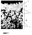
- Fig. 1 shows a microscopic micrograph of the interface between the Material layers A and B of a composite body according to the invention.
- the gray ones Areas (1) are SiC particles which are approximately uniform over the entire Neckline are distributed.
- Material layer A surrounding material B is for flat components
- the composite bodies are made by the metal-liquid infiltration of Porous green bodies containing SiC, carbon and nitride.
- the porous carbon-containing green body In the manufacture of the porous carbon-containing green body, one is first Mixture of the solids containing silicon carbide, nitrides, if appropriate Carbon and organic binder made. This mixture is made according to the usual processes in the ceramic industry (including pressing, injection molding, Slip) brought into shape, the curing of the organic binder for the Strength of the resulting body is responsible. The hardened body will followed by a temperature treatment in the range of approx. 650 to 1600 ° C, preferably 1000 ° C, carbonized. According to the invention, the organic binder carbonizable, that is, when heated under non-oxidizing conditions the binder does not evaporate completely, but it forms Carbon residue. The resulting body, the green body, exists now from the solids used, especially the ceramic particles held together by a binding phase made of pyrolytically produced carbon become.
- the composition of the starting mixture is preferably chosen so that the Mass fraction of silicon carbide in the porous carbon-containing green body is at least 50%, preferably at least 65%.
- the mass fraction of Carbon, from carbonized binder and solids used, is typically above 4% and preferably above 8%, the mass fraction nitride content above 1%, preferably above 3% and particularly preferably between 3 and 12%.
- the nitrides are particularly selected from at least one of the nitrides of the following elements: Ti, Zr, Si, B and Al.
- the carbon material used as a solid is selected from the group Coal, coke, natural graphite, technical graphite, carbonized organic material, Carbon fibers, glassy carbon and coking products. Particularly suitable are natural graphite or synthetic graphite.
- a major advantage of the invention is that almost on expensive carbon fibers can be completely or completely dispensed with.
- step b) the supply of a molten metal, a carbide-forming metal is in infiltrates the porous green body.
- the infiltration is caused by the capillary action and the chemical reaction between the free one that occurs during infiltration Carbon of the green body supported with the carbide-forming metal.
- the infiltration takes place at reduced pressure or vacuum, at Temperatures of approx. 150 ° C above the melting temperature of the Infiltration metal.
- Silicon alloys typically made of Si, are preferred as the infiltration metal and at least one of the elements Ti, Fe, Cr and Mo, and particularly preferred technically pure Si used.
- the Mass fraction of infiltration metal supplied by the infiltration inside the composite material according to the invention is typically below 1%, and the mass fraction of by that Infiltration metal newly formed metal carbide below 3%.
- the chemical composition and the porosity of the Green body and the infiltration metal range chosen so that the green body only is partially infiltrated.
- the depth of infiltration can be specifically controlled.
- the nitrides wetting the green body with the molten Silicon deteriorates.
- the depth of infiltration of the silicon-containing melt reduces and the degree of implementation of the green body controlled.
- step c) the conversion of at least part of the free carbon takes place the infiltration metal instead. Especially about temperature and process time sales are controlled.
- a dense ceramic is formed in material layer A.
- material layer B where almost none Infiltration metal arrives at the temperature of step c) Sintering reaction takes place between the ceramic particles, which among other things leads to a mechanical stabilization of the material layer leads.
- the firmness (Breaking strength) only has to be so high that material B can be handled and does not disintegrate easily.
- the actual mechanical stabilization of the Material layer B takes place via the firmly attached material layer A.
- the Strength of layer B can be increased if the mixture for the green body Sintering aids are added, preferably Si compounds or powders contain.
- the molten metal is usually over wicks or over Metal powder fillings fed. Typically, the metal infiltration takes place in the essentially over the entire surface, so that the material layer A a closed material surface results. Become plate-shaped green bodies used, results in a component that in the direction of the surface normal, the preferred direction of the ballistic threat, the layer sequence of the Material layers A B A has.
- the mechanical stability of the material layer B can be improved without the properties according to the invention, which are similar to a loose powder bed, being lost if the pores of the material B are additionally filled with a soft material.
- This can be achieved, for example, by melt infiltration with a thermoplastic polymer or by liquid infiltration with a polymer resin.
- the pores are preferably filled at least 30% with polyolefins or epoxy resins.
- the pores are infiltrated with adhesives which are particularly suitable for bonding to a backing. Backing materials made from aramid fibers are particularly suitable.
- the composite body in particular the material layer B, with a light metal, in particular Al, infiltrated.
- the residual porosity lies in the Layer B preferably below 15%.
- the filling of the pores of the material layer B with a polymer can be special advantageous for gluing with a backing, in particular a backing Fiber mats or fabrics can be used.
Landscapes
- Engineering & Computer Science (AREA)
- Chemical & Material Sciences (AREA)
- Ceramic Engineering (AREA)
- General Engineering & Computer Science (AREA)
- Ceramic Products (AREA)
- Laminated Bodies (AREA)
- Aiming, Guidance, Guns With A Light Source, Armor, Camouflage, And Targets (AREA)
- Compositions Of Oxide Ceramics (AREA)
Applications Claiming Priority (2)
| Application Number | Priority Date | Filing Date | Title |
|---|---|---|---|
| DE2002131278 DE10231278A1 (de) | 2002-07-10 | 2002-07-10 | Keramische Verbundkörper |
| DE10231278 | 2002-07-10 |
Publications (3)
| Publication Number | Publication Date |
|---|---|
| EP1380809A2 true EP1380809A2 (fr) | 2004-01-14 |
| EP1380809A3 EP1380809A3 (fr) | 2004-05-26 |
| EP1380809B1 EP1380809B1 (fr) | 2006-10-11 |
Family
ID=29723841
Family Applications (1)
| Application Number | Title | Priority Date | Filing Date |
|---|---|---|---|
| EP20030015441 Expired - Lifetime EP1380809B1 (fr) | 2002-07-10 | 2003-07-09 | Corps composite céramique |
Country Status (5)
| Country | Link |
|---|---|
| US (1) | US7128963B2 (fr) |
| EP (1) | EP1380809B1 (fr) |
| AT (1) | ATE342485T1 (fr) |
| DE (2) | DE10231278A1 (fr) |
| ES (1) | ES2274146T3 (fr) |
Cited By (6)
| Publication number | Priority date | Publication date | Assignee | Title |
|---|---|---|---|---|
| EP1643207A1 (fr) * | 2004-09-30 | 2006-04-05 | Vlad Lucuta | Composants en céramique avec revêtement diamant pour applications blindés |
| WO2018011477A1 (fr) | 2016-07-11 | 2018-01-18 | Saint-Gobain Centre De Recherches Et D'etudes Europeen | Plaque de blindage |
| EP3473965A1 (fr) * | 2017-10-20 | 2019-04-24 | BAE SYSTEMS plc | Ensemble de blindage |
| WO2019077310A1 (fr) * | 2017-10-20 | 2019-04-25 | Bae Systems Plc | Ensemble blindage |
| WO2022003300A1 (fr) | 2020-07-02 | 2022-01-06 | Saint-Gobain Centre De Recherches Et D'etudes Europeen | Element de blindage profile |
| WO2022007377A1 (fr) * | 2020-07-09 | 2022-01-13 | 南京航空航天大学 | Matériau composite amélioré par une préforme fibreuse tissée mélangée et procédé de préparation associé |
Families Citing this family (24)
| Publication number | Priority date | Publication date | Assignee | Title |
|---|---|---|---|---|
| FR876M (fr) | 1960-10-12 | 1961-10-16 | ||
| US7661228B1 (en) | 2005-05-06 | 2010-02-16 | Kontek Industries, Inc. | Armored building modules and panels |
| US20110113950A1 (en) * | 2006-01-10 | 2011-05-19 | Reed Charles K | Composite material having a layer including entrained particles and method of making same |
| DE102006031113B4 (de) * | 2006-06-28 | 2009-02-26 | Fraunhofer-Gesellschaft zur Förderung der angewandten Forschung e.V. | Verfahren zur Herstellung eines keramischen Verbundwerkstoffes |
| US8689671B2 (en) | 2006-09-29 | 2014-04-08 | Federal-Mogul World Wide, Inc. | Lightweight armor and methods of making |
| JP4327190B2 (ja) * | 2006-10-11 | 2009-09-09 | 日本碍子株式会社 | Si−SiC質焼結体及びその製造方法 |
| US9116428B1 (en) | 2009-06-01 | 2015-08-25 | Hrl Laboratories, Llc | Micro-truss based energy absorption apparatus |
| US8087339B2 (en) * | 2007-07-24 | 2012-01-03 | Foster-Miller, Inc. | Armor system |
| CN101815920A (zh) * | 2007-09-28 | 2010-08-25 | 通用动力陆地系统公司 | 用于改进的轻质装甲防护的装置、方法及系统 |
| US8105967B1 (en) | 2007-10-05 | 2012-01-31 | The United States Of America As Represented By The Secretary Of The Navy | Lightweight ballistic armor including non-ceramic-infiltrated reaction-bonded-ceramic composite material |
| US7685922B1 (en) | 2007-10-05 | 2010-03-30 | The United States Of America As Represented By The Secretary Of The Navy | Composite ballistic armor having geometric ceramic elements for shock wave attenuation |
| US8155496B1 (en) * | 2009-06-01 | 2012-04-10 | Hrl Laboratories, Llc | Composite truss armor |
| EP2365949A2 (fr) * | 2009-07-07 | 2011-09-21 | Morgan Advanced Materials And Technology Inc. | Article hybride céramique dure non oxyde ou oxyde/composite de céramique dure non oxyde ou oxyde |
| JP5737547B2 (ja) * | 2009-09-04 | 2015-06-17 | 東洋炭素株式会社 | 炭化ケイ素被覆黒鉛粒子の製造方法及び炭化ケイ素被覆黒鉛粒子 |
| USD638583S1 (en) | 2010-01-11 | 2011-05-24 | Soldier Technology and Armor Research Industries, LLC | Torso protection assembly |
| USD628753S1 (en) | 2010-01-11 | 2010-12-07 | Soldier Technology and Armor Research Industries, LLC | Forearm protection system |
| USD644380S1 (en) | 2010-01-11 | 2011-08-30 | Soldier Technology and Armor Research Industries, LLC | Upper arm protection system |
| USD630385S1 (en) | 2010-01-11 | 2011-01-04 | Soldier Technology and Armor Research Industries, LLC | Shin guard protection system |
| US20110231985A1 (en) * | 2010-01-12 | 2011-09-29 | Bishop Lyman J | Body Armor Protection System |
| US9696122B2 (en) | 2011-06-30 | 2017-07-04 | Imi Systems Ltd. | Antiballistic article and method of producing same |
| IL213865A (en) | 2011-06-30 | 2017-02-28 | Bergman Ron | Anti-ballistic product and method of manufacture |
| US9366506B2 (en) | 2012-09-19 | 2016-06-14 | Aps Materials, Inc. | Coated ballistic structures and methods of making same |
| IL230775B (en) | 2014-02-02 | 2018-12-31 | Imi Systems Ltd | Pre-stressed curved ceramic panels/tiles and a method for their production |
| WO2021011650A1 (fr) * | 2019-07-17 | 2021-01-21 | Phillips 66 Company | Particules d'électrode appropriées pour des batteries |
Family Cites Families (14)
| Publication number | Priority date | Publication date | Assignee | Title |
|---|---|---|---|---|
| US3954483A (en) * | 1974-01-08 | 1976-05-04 | General Electric Company | Dense polycrystalline silicon carbide |
| US4120731A (en) * | 1976-02-23 | 1978-10-17 | General Electric Company | Method of making molten silicon infiltration reaction products and products made thereby |
| EP0215132B1 (fr) * | 1985-03-12 | 1991-10-02 | Kvk Co., Ltd. | Soupape a corps de soupape en un compose ceramique |
| EP0287918A1 (fr) * | 1987-04-13 | 1988-10-26 | Cemcom Corporation | Matériau de blindage céramique formé par liaison chimique |
| FR2642419A1 (fr) | 1988-12-19 | 1990-08-03 | Europ Propulsion | Materiau de protection a structure ceramique multi-couches |
| US5432253A (en) * | 1989-12-18 | 1995-07-11 | General Electric Company | Composite containing fibrous material |
| JPH05221723A (ja) * | 1992-02-07 | 1993-08-31 | Toshiba Ceramics Co Ltd | Si−SiC複合材料 |
| US5580834A (en) * | 1993-02-10 | 1996-12-03 | The Morgan Crucible Company Plc | Self-sintered silicon carbide/carbon graphite composite material having interconnected pores which may be impregnated and raw batch and process for producing same |
| DE4438456C2 (de) * | 1994-10-28 | 2002-07-11 | Deutsch Zentr Luft & Raumfahrt | Reibeinheit |
| DE19642506C1 (de) * | 1996-10-15 | 1997-10-23 | Sibco Gmbh | Erzeugnis auf der Basis von Kohlenstoff und Kohlenfaserstoffen, Karbiden und/oder Di-Karbiden und Verfahren zu seiner Herstellung sowie Verwendung des Erzeugnisses |
| JP4014254B2 (ja) * | 1997-07-18 | 2007-11-28 | 日本碍子株式会社 | Si濃度段階的変化型Si−SiC材料及びSi濃度段階的変化型SiC繊維強化Si−SiC複合材料並びにこれらの製造方法 |
| JP3652900B2 (ja) * | 1997-12-16 | 2005-05-25 | 日本碍子株式会社 | 繊維複合材料およびその用途 |
| DE19834018C1 (de) * | 1998-07-28 | 2000-02-03 | Deutsch Zentr Luft & Raumfahrt | Verfahren zum Erzeugen einer Siliziumkarbid enthaltenden Schutzschicht |
| DE19947731B4 (de) * | 1999-10-05 | 2005-06-23 | Deutsches Zentrum für Luft- und Raumfahrt e.V. | Verfahren zur Herstellung eines Bauteils aus SiC-Keramik sowie danach hergestelltes Halbzeug |
-
2002
- 2002-07-10 DE DE2002131278 patent/DE10231278A1/de not_active Withdrawn
-
2003
- 2003-07-09 ES ES03015441T patent/ES2274146T3/es not_active Expired - Lifetime
- 2003-07-09 AT AT03015441T patent/ATE342485T1/de not_active IP Right Cessation
- 2003-07-09 EP EP20030015441 patent/EP1380809B1/fr not_active Expired - Lifetime
- 2003-07-09 DE DE50305325T patent/DE50305325D1/de not_active Expired - Fee Related
- 2003-07-10 US US10/617,640 patent/US7128963B2/en not_active Expired - Fee Related
Cited By (10)
| Publication number | Priority date | Publication date | Assignee | Title |
|---|---|---|---|---|
| EP1643207A1 (fr) * | 2004-09-30 | 2006-04-05 | Vlad Lucuta | Composants en céramique avec revêtement diamant pour applications blindés |
| US8113104B2 (en) | 2004-09-30 | 2012-02-14 | Aceram Materials and Technologies, Inc. | Ceramic components with diamond coating for armor applications |
| WO2018011477A1 (fr) | 2016-07-11 | 2018-01-18 | Saint-Gobain Centre De Recherches Et D'etudes Europeen | Plaque de blindage |
| US11635281B2 (en) | 2016-07-11 | 2023-04-25 | Saint-Gobain Centre De Recherches Et D'etudes Europeen | Armour plate |
| EP3473965A1 (fr) * | 2017-10-20 | 2019-04-24 | BAE SYSTEMS plc | Ensemble de blindage |
| WO2019077310A1 (fr) * | 2017-10-20 | 2019-04-25 | Bae Systems Plc | Ensemble blindage |
| WO2022003300A1 (fr) | 2020-07-02 | 2022-01-06 | Saint-Gobain Centre De Recherches Et D'etudes Europeen | Element de blindage profile |
| FR3112201A3 (fr) | 2020-07-02 | 2022-01-07 | Saint-Gobain Centre De Recherches Et D'etudes Europeen | Element de blindage profile |
| US12050088B2 (en) | 2020-07-02 | 2024-07-30 | Saint-Gobain Centre De Recherches Et D'etudes Europeen | Profiled screening element |
| WO2022007377A1 (fr) * | 2020-07-09 | 2022-01-13 | 南京航空航天大学 | Matériau composite amélioré par une préforme fibreuse tissée mélangée et procédé de préparation associé |
Also Published As
| Publication number | Publication date |
|---|---|
| DE50305325D1 (de) | 2006-11-23 |
| DE10231278A1 (de) | 2004-02-05 |
| EP1380809A3 (fr) | 2004-05-26 |
| ES2274146T3 (es) | 2007-05-16 |
| US7128963B2 (en) | 2006-10-31 |
| US20040197542A1 (en) | 2004-10-07 |
| ATE342485T1 (de) | 2006-11-15 |
| EP1380809B1 (fr) | 2006-10-11 |
Similar Documents
| Publication | Publication Date | Title |
|---|---|---|
| EP1380809B1 (fr) | Corps composite céramique | |
| DE10157487C1 (de) | Faserverstärkter Verbundkörper für Schutzpanzerungen, seine Herstellung und Verwendungen | |
| DE102015223236A1 (de) | Keramisches Bauteil | |
| DE19953259C2 (de) | Verbunde aus einem mit Fasern verstärkten Verbundwerkstoff mit keramischer Matrix und einem Backing und Verwendung der Verbunde | |
| DE69828168T2 (de) | Kohlenstoffverbundwerkstoffe | |
| US5443917A (en) | Ceramic armor | |
| DE19856721A1 (de) | Verfahren zur Herstellung eines mittels Kohlenstoffkurzfasern verstärkten Siliciumcarbid-Verbundwerkstoffes | |
| EP1538417B1 (fr) | Matériau de blindage multicouche et procédé pour sa fabrication | |
| WO2009080009A1 (fr) | Procédé de fabrication d'éléments de construction pourvus d'un revêtement anti-usure, élément de construction ainsi fabriqué, et son utilisation | |
| EP2809628B1 (fr) | Matériaux composites à base de carbure de silicium renforcés par des fibres | |
| WO2008043679A2 (fr) | Matériau composite, structure composite, et procédé de production associé | |
| DE602005004713T2 (de) | Keramischer Körper mit Diamantbeschichtung für gepanzerte Anwendungen. | |
| DE102007060611A1 (de) | Fluidische Panzeranordnung | |
| DE112022005944T5 (de) | Neuartige funktional abgestufte kugelsichere Multiphasen-Hybridpanzerung | |
| EP0994084B1 (fr) | Blindage de protection | |
| DE102004016874C5 (de) | Verbundwerkstoff, Verfahren zu seiner Herstellung und seine Verwendung | |
| DE102007025894B4 (de) | Glaskeramik-Panzermaterial | |
| WO2022218540A1 (fr) | Corps moulé composite constitué d'une céramique mixte liée par réaction infiltrée avec du silicium | |
| DE69609330T2 (de) | Verfahren zur herstellung eines verbundwerkstoffes | |
| DE10303351B3 (de) | Bauteil aus Metall/Keramik-Verbundwerkstoff mit intermetallischer Matrix, dessen Verwendung als Panzermaterial und Verfahren zu dessen Herstellung | |
| DE10323082A1 (de) | Schichtverbundwerkstoff aus Metall und Faserverstärkter Keramik | |
| EP3141863B1 (fr) | Composant pour applications de protection balistique et son procede de fabrication | |
| DE19856597B4 (de) | Schutzpanzerung | |
| DE102009053737A1 (de) | Bremsbelag, Verfahren zur Herstellung eines solchen Bremsbelags sowie Bremseinheit umfassend einen solchen Bremsbelag | |
| DE102006031113B4 (de) | Verfahren zur Herstellung eines keramischen Verbundwerkstoffes |
Legal Events
| Date | Code | Title | Description |
|---|---|---|---|
| PUAI | Public reference made under article 153(3) epc to a published international application that has entered the european phase |
Free format text: ORIGINAL CODE: 0009012 |
|
| AK | Designated contracting states |
Kind code of ref document: A2 Designated state(s): AT BE BG CH CY CZ DE DK EE ES FI FR GB GR HU IE IT LI LU MC NL PT RO SE SI SK TR |
|
| AX | Request for extension of the european patent |
Extension state: AL LT LV MK |
|
| PUAL | Search report despatched |
Free format text: ORIGINAL CODE: 0009013 |
|
| AK | Designated contracting states |
Kind code of ref document: A3 Designated state(s): AT BE BG CH CY CZ DE DK EE ES FI FR GB GR HU IE IT LI LU MC NL PT RO SE SI SK TR |
|
| AX | Request for extension of the european patent |
Extension state: AL LT LV MK |
|
| 17P | Request for examination filed |
Effective date: 20041126 |
|
| AKX | Designation fees paid |
Designated state(s): AT BE BG CH CY CZ DE DK EE ES FI FR GB GR HU IE IT LI LU MC NL PT RO SE SI SK TR |
|
| 17Q | First examination report despatched |
Effective date: 20050302 |
|
| GRAP | Despatch of communication of intention to grant a patent |
Free format text: ORIGINAL CODE: EPIDOSNIGR1 |
|
| RTI1 | Title (correction) |
Free format text: CERAMIC COMPOSITE BODY |
|
| GRAS | Grant fee paid |
Free format text: ORIGINAL CODE: EPIDOSNIGR3 |
|
| GRAA | (expected) grant |
Free format text: ORIGINAL CODE: 0009210 |
|
| AK | Designated contracting states |
Kind code of ref document: B1 Designated state(s): AT BE BG CH CY CZ DE DK EE ES FI FR GB GR HU IE IT LI LU MC NL PT RO SE SI SK TR |
|
| PG25 | Lapsed in a contracting state [announced via postgrant information from national office to epo] |
Ref country code: FI Free format text: LAPSE BECAUSE OF FAILURE TO SUBMIT A TRANSLATION OF THE DESCRIPTION OR TO PAY THE FEE WITHIN THE PRESCRIBED TIME-LIMIT Effective date: 20061011 Ref country code: RO Free format text: LAPSE BECAUSE OF FAILURE TO SUBMIT A TRANSLATION OF THE DESCRIPTION OR TO PAY THE FEE WITHIN THE PRESCRIBED TIME-LIMIT Effective date: 20061011 Ref country code: SI Free format text: LAPSE BECAUSE OF FAILURE TO SUBMIT A TRANSLATION OF THE DESCRIPTION OR TO PAY THE FEE WITHIN THE PRESCRIBED TIME-LIMIT Effective date: 20061011 Ref country code: SK Free format text: LAPSE BECAUSE OF FAILURE TO SUBMIT A TRANSLATION OF THE DESCRIPTION OR TO PAY THE FEE WITHIN THE PRESCRIBED TIME-LIMIT Effective date: 20061011 Ref country code: CZ Free format text: LAPSE BECAUSE OF FAILURE TO SUBMIT A TRANSLATION OF THE DESCRIPTION OR TO PAY THE FEE WITHIN THE PRESCRIBED TIME-LIMIT Effective date: 20061011 Ref country code: NL Free format text: LAPSE BECAUSE OF FAILURE TO SUBMIT A TRANSLATION OF THE DESCRIPTION OR TO PAY THE FEE WITHIN THE PRESCRIBED TIME-LIMIT Effective date: 20061011 |
|
| REG | Reference to a national code |
Ref country code: GB Ref legal event code: FG4D Free format text: NOT ENGLISH |
|
| REG | Reference to a national code |
Ref country code: CH Ref legal event code: EP |
|
| REG | Reference to a national code |
Ref country code: IE Ref legal event code: FG4D Free format text: LANGUAGE OF EP DOCUMENT: GERMAN |
|
| REF | Corresponds to: |
Ref document number: 50305325 Country of ref document: DE Date of ref document: 20061123 Kind code of ref document: P |
|
| REG | Reference to a national code |
Ref country code: CH Ref legal event code: NV Representative=s name: KELLER & PARTNER PATENTANWAELTE AG WINTERTHUR |
|
| PG25 | Lapsed in a contracting state [announced via postgrant information from national office to epo] |
Ref country code: SE Free format text: LAPSE BECAUSE OF FAILURE TO SUBMIT A TRANSLATION OF THE DESCRIPTION OR TO PAY THE FEE WITHIN THE PRESCRIBED TIME-LIMIT Effective date: 20070111 Ref country code: DK Free format text: LAPSE BECAUSE OF FAILURE TO SUBMIT A TRANSLATION OF THE DESCRIPTION OR TO PAY THE FEE WITHIN THE PRESCRIBED TIME-LIMIT Effective date: 20070111 Ref country code: BG Free format text: LAPSE BECAUSE OF FAILURE TO SUBMIT A TRANSLATION OF THE DESCRIPTION OR TO PAY THE FEE WITHIN THE PRESCRIBED TIME-LIMIT Effective date: 20070111 |
|
| GBT | Gb: translation of ep patent filed (gb section 77(6)(a)/1977) |
Effective date: 20070110 |
|
| PG25 | Lapsed in a contracting state [announced via postgrant information from national office to epo] |
Ref country code: PT Free format text: LAPSE BECAUSE OF FAILURE TO SUBMIT A TRANSLATION OF THE DESCRIPTION OR TO PAY THE FEE WITHIN THE PRESCRIBED TIME-LIMIT Effective date: 20070319 |
|
| NLV1 | Nl: lapsed or annulled due to failure to fulfill the requirements of art. 29p and 29m of the patents act | ||
| REG | Reference to a national code |
Ref country code: ES Ref legal event code: FG2A Ref document number: 2274146 Country of ref document: ES Kind code of ref document: T3 |
|
| ET | Fr: translation filed | ||
| PLBE | No opposition filed within time limit |
Free format text: ORIGINAL CODE: 0009261 |
|
| STAA | Information on the status of an ep patent application or granted ep patent |
Free format text: STATUS: NO OPPOSITION FILED WITHIN TIME LIMIT |
|
| 26N | No opposition filed |
Effective date: 20070712 |
|
| BERE | Be: lapsed |
Owner name: SGL CARBON A.G. Effective date: 20070731 |
|
| PG25 | Lapsed in a contracting state [announced via postgrant information from national office to epo] |
Ref country code: MC Free format text: LAPSE BECAUSE OF NON-PAYMENT OF DUE FEES Effective date: 20070731 Ref country code: GR Free format text: LAPSE BECAUSE OF FAILURE TO SUBMIT A TRANSLATION OF THE DESCRIPTION OR TO PAY THE FEE WITHIN THE PRESCRIBED TIME-LIMIT Effective date: 20070112 |
|
| PG25 | Lapsed in a contracting state [announced via postgrant information from national office to epo] |
Ref country code: BE Free format text: LAPSE BECAUSE OF NON-PAYMENT OF DUE FEES Effective date: 20070731 |
|
| PG25 | Lapsed in a contracting state [announced via postgrant information from national office to epo] |
Ref country code: EE Free format text: LAPSE BECAUSE OF FAILURE TO SUBMIT A TRANSLATION OF THE DESCRIPTION OR TO PAY THE FEE WITHIN THE PRESCRIBED TIME-LIMIT Effective date: 20061011 |
|
| PG25 | Lapsed in a contracting state [announced via postgrant information from national office to epo] |
Ref country code: CY Free format text: LAPSE BECAUSE OF FAILURE TO SUBMIT A TRANSLATION OF THE DESCRIPTION OR TO PAY THE FEE WITHIN THE PRESCRIBED TIME-LIMIT Effective date: 20061011 Ref country code: LU Free format text: LAPSE BECAUSE OF NON-PAYMENT OF DUE FEES Effective date: 20070709 |
|
| PG25 | Lapsed in a contracting state [announced via postgrant information from national office to epo] |
Ref country code: TR Free format text: LAPSE BECAUSE OF FAILURE TO SUBMIT A TRANSLATION OF THE DESCRIPTION OR TO PAY THE FEE WITHIN THE PRESCRIBED TIME-LIMIT Effective date: 20061011 Ref country code: HU Free format text: LAPSE BECAUSE OF FAILURE TO SUBMIT A TRANSLATION OF THE DESCRIPTION OR TO PAY THE FEE WITHIN THE PRESCRIBED TIME-LIMIT Effective date: 20070412 |
|
| PGFP | Annual fee paid to national office [announced via postgrant information from national office to epo] |
Ref country code: ES Payment date: 20090722 Year of fee payment: 7 Ref country code: FR Payment date: 20090716 Year of fee payment: 7 Ref country code: IE Payment date: 20090723 Year of fee payment: 7 |
|
| PGFP | Annual fee paid to national office [announced via postgrant information from national office to epo] |
Ref country code: AT Payment date: 20090715 Year of fee payment: 7 Ref country code: CH Payment date: 20090715 Year of fee payment: 7 Ref country code: DE Payment date: 20090731 Year of fee payment: 7 Ref country code: GB Payment date: 20090720 Year of fee payment: 7 |
|
| PGFP | Annual fee paid to national office [announced via postgrant information from national office to epo] |
Ref country code: IT Payment date: 20090727 Year of fee payment: 7 |
|
| REG | Reference to a national code |
Ref country code: CH Ref legal event code: PL |
|
| GBPC | Gb: european patent ceased through non-payment of renewal fee |
Effective date: 20100709 |
|
| REG | Reference to a national code |
Ref country code: FR Ref legal event code: ST Effective date: 20110331 |
|
| PG25 | Lapsed in a contracting state [announced via postgrant information from national office to epo] |
Ref country code: CH Free format text: LAPSE BECAUSE OF NON-PAYMENT OF DUE FEES Effective date: 20100731 Ref country code: DE Free format text: LAPSE BECAUSE OF NON-PAYMENT OF DUE FEES Effective date: 20110201 Ref country code: LI Free format text: LAPSE BECAUSE OF NON-PAYMENT OF DUE FEES Effective date: 20100731 |
|
| REG | Reference to a national code |
Ref country code: DE Ref legal event code: R119 Ref document number: 50305325 Country of ref document: DE Effective date: 20110201 |
|
| PG25 | Lapsed in a contracting state [announced via postgrant information from national office to epo] |
Ref country code: FR Free format text: LAPSE BECAUSE OF NON-PAYMENT OF DUE FEES Effective date: 20100802 Ref country code: IT Free format text: LAPSE BECAUSE OF NON-PAYMENT OF DUE FEES Effective date: 20100709 Ref country code: AT Free format text: LAPSE BECAUSE OF NON-PAYMENT OF DUE FEES Effective date: 20100709 |
|
| PG25 | Lapsed in a contracting state [announced via postgrant information from national office to epo] |
Ref country code: GB Free format text: LAPSE BECAUSE OF NON-PAYMENT OF DUE FEES Effective date: 20100709 Ref country code: IE Free format text: LAPSE BECAUSE OF NON-PAYMENT OF DUE FEES Effective date: 20100709 |
|
| REG | Reference to a national code |
Ref country code: ES Ref legal event code: FD2A Effective date: 20110818 |
|
| PG25 | Lapsed in a contracting state [announced via postgrant information from national office to epo] |
Ref country code: ES Free format text: LAPSE BECAUSE OF NON-PAYMENT OF DUE FEES Effective date: 20100710 |