EP1380824A2 - Arrangement pour mesurer une charge - Google Patents
Arrangement pour mesurer une charge Download PDFInfo
- Publication number
- EP1380824A2 EP1380824A2 EP20030254393 EP03254393A EP1380824A2 EP 1380824 A2 EP1380824 A2 EP 1380824A2 EP 20030254393 EP20030254393 EP 20030254393 EP 03254393 A EP03254393 A EP 03254393A EP 1380824 A2 EP1380824 A2 EP 1380824A2
- Authority
- EP
- European Patent Office
- Prior art keywords
- load cell
- assembly
- load
- engagement member
- upper engagement
- Prior art date
- Legal status (The legal status is an assumption and is not a legal conclusion. Google has not performed a legal analysis and makes no representation as to the accuracy of the status listed.)
- Withdrawn
Links
Images


Classifications
-
- G—PHYSICS
- G01—MEASURING; TESTING
- G01G—WEIGHING
- G01G19/00—Weighing apparatus or methods adapted for special purposes not provided for in the preceding groups
- G01G19/14—Weighing apparatus or methods adapted for special purposes not provided for in the preceding groups for weighing suspended loads
- G01G19/18—Weighing apparatus or methods adapted for special purposes not provided for in the preceding groups for weighing suspended loads having electrical weight-sensitive devices
Definitions
- This invention relates to load assemblies such as may be, although non-exclusively, used to support load cells used to measure loads in tension or compression and for methods of measuring forces using a load cell.
- Load cells are commonly of the form of a beam on which a load can be applied which is shaped such that a region of the beam deforms in a known manner.
- Strain gauges which exhibit a known change in resistance for a given deformation, can be applied to the region. Therefore, measurement of the resistance of the strain gauges gives an indication of the load on the load cell.
- S-beam load cell is of the form of an S-shaped beam, with a thinned out section or sections at or near the centre of the S.
- the strain gauges are mounted on these thinned out sections.
- Such a load cell is generally supported by the top of the S and a load applied at the bottom.
- load cell is of the form of a beam, with a thinned out section or sections along its length. Strain gauges are mounted on these thinned out sections. Such a load cell is generally supported either by one end, with the load applied to the other end of the load cell, or by both ends, with the load applied to the centre of the load cell.
- an assembly for use in suspending loads from a load cell comprising:
- this provides a load assembly that can support a load in the inoperative position but allows the load cell to take the load in the second, operative, position. Accordingly, the load cell may be removed in the inoperative position and replaced or otherwise maintained as necessary.
- the load cell with which the assembly is adapted to be used with may be an S-beam load cell.
- the assembly may conveniently include means adapted to switch the assembly between inoperative and operative positions.
- This may be lifting means, which is adapted to lift the lower part off the upper part.
- the lifting means is adapted to lift the lower part by lifting the load cell.
- the lifting means may comprise an upper engagement member, by means of which the upper part is adapted to engage the load cell, and a lower engagement member by means of which the lower part is adapted to engage the load cell.
- the lower engagement member may fix the lower part vertically relative to the load cell, whilst the upper engagement member may allow controlled movement of the load cell relative to the upper part. Such movement may have a vertical component, and may indeed be entirely vertical. Accordingly, at least a portion of the upper engagement member may move vertically relative to the upper part.
- the upper engagement member may be adapted to rotate about an axis. It may have a portion offset from this axis.
- the upper engagement member may be adapted to engage the load cell at this offset portion.
- the upper engagement member may comprise a cranked shaft.
- the upper part may be provided with a series of holes through which the upper engagement member may removably pass.
- the upper engagement member may be removable and re-insertable from the upper part by sliding along the length of the shaft through the holes.
- the holes that the offset portion pass in order to remove the upper engagement member may be elongate in order to allow easy removal and re-insertion of the upper engagement member.
- At least one of the holes may be in at least one, but preferably two, forks depending from the upper part into the interior thereof. These forks may provide part of the connection between the load cell and the upper part.
- the assembly may be adapted to engage the load cell using the offset portion of the upper engagement member. Accordingly, rotation of the upper engagement member may cause the load cell to lift and hence the lower part no longer rests on the upper part. This provides means for switching between the inoperative and operative positions.
- the upper engagement member may further comprise a handle, by means of which rotation of the shaft is facilitated.
- the handle may be connected perpendicularly to the first shaft, possibly at an end thereof.
- a handle especially if it extends away from the axis of the shaft further than the offset portion, enables the load to be lifted into the operative position by a user.
- the handle may be securable to the upper part such that, in use, the upper engagement member cannot rotate.
- the handle may be, in the operative position, securable to the upper part.
- the secural of the handle to the upper part may be achieved by means of a screw passing through a hole in the handle and being received in a captive nut in the upper part.
- the lower part may be provided with at least one, but preferably two, forks depending therefrom, which may engage the lower engagement member.
- the lower engagement member may comprise a further shaft introduced through the, or each, of the forks of the lower part.
- the assembly may be positionable in a further, "transit", position in which the lower part is secured to the upper part.
- the further shaft may secure the upper part to the lower part.
- the further shaft In the transit position, the further shaft may pass through at least one of the, or each, fork and through a secural hole in the upper part.
- the upper engagement member may be secured to the upper part. Accordingly, in the transit position the parts of the assembly are protected against movement relative to one another.
- the upper part may include a captive nut by means of which the upper part is secured to the anchor point.
- the lower part may include a captive nut by means of which it is adapted to be connected to the load.
- the upper part may be of the form of a frame surrounding an interior space, with an orifice providing communication between interior and exterior.
- the lower part may, in the inoperative position, rest on inner walls of the upper part in the region of the orifice.
- the assembly is arranged so that the lower part cannot fall through the orifice. This means that should part of the assembly or the load cell fail, the load will still be supported.
- a combination of an assembly for use in suspending loads from a load cell and a load cell comprising:
- the load cell may be an S-beam load cell.
- the load cell is adapted to pivot about its connection to the upper part, which may be the offset portion of the upper engagement member.
- the surface of the upper part upon which the lower part, in the inoperative position, rests may substantially define a section of the surface of a sphere with a centre at the point about which the load cell is adapted to pivot.
- the load cell may comprise one or more loading adaptors by means of which the load cell engages the engagement members.
- Each loading adaptor may be fixed to an end of the load cell and may define an aperture.
- the aperture may have bevelled sides such that the loading adaptor may pivot about all three axes relative to any member introduced into the aperture.
- the combination may further have any of the features described above in relation to the assembly of the first aspect of the invention.
- a method of measuring the force due to a load comprising:
- the assembly may be the assembly of the first aspect of the invention.
- the step of causing the assembly to transfer the load to the load cell may comprise lifting a body associated with the load cell at least partially off a rest.
- the body may lift completely off the rest.
- the rest may, when the body is resting thereon, support the load.
- Lifting may be achieved by means of rotation of a cranked shaft.
- the cranked shaft may, in use of the assembly, be secured against unwanted rotation.
- the method may further comprise the step of allowing the body to fall back onto the rest should part of the assembly fail. Furthermore, the method may include the step of lowering the body back onto the rest such that the load cell may be removed.
- an assembly for use in supporting loads on a load cell comprising:
- Movement of the upper part relative to the load cell allows the load to be supported, which allows removal of the load cell.
- the movement is preferably at least partially vertical, and the upper engagement member may be adapted to raise the upper part relative to the load cell from the operative position to a raised position.
- the assembly may include fixing means, which are adapted to fix the upper and lower parts together and hence support the upper part on the lower part. They may be adapted to be introduced in the raised position of the upper part, upon which the upper engagement member may lower the upper part onto the fixing means.
- the fixing means may be chocks, sized to fit within a gap between the upper and lower parts in the raised position.
- the upper engagement member is adapted to rotate about an axis. It may have at least one portion offset from this axis.
- the upper engagement member may be adapted to engage the load cell at this offset portion.
- the upper engagement member may engage the upper part such that rotation of the upper engagement member about the axis of rotation causes the upper part to move relative to the load cell.
- the upper engagement member may comprise a cranked shaft, and the upper part may be provided with lugs by means of which the upper part engages the upper engagement member at uncranked portions thereof.
- the upper engagement member may further comprise a handle, by means of which rotation of the shaft is facilitated.
- a handle makes lifting the load to be lifted into the operative position by a user much easier.
- the handle may be securable to the upper part such that, in use, the upper engagement member cannot rotate.
- the handle may be, in the operative position, securable to the upper part.
- the secural of the handle to the upper part may be achieved by means of a screw passing through a hole in the handle and being received in a captive nut in the upper part.
- a combination of an assembly for use in supporting loads on a load cell comprising an assembly according to the fourth aspect of the invention and a load cell.
- the load cell may be a shear beam load cell.
- the load cell may engage the upper engagement member about a groove in the load cell.
- the combination may have any of the optional features of the fourth aspect of the invention.
- a method of removing a load cell from a load assembly comprising causing the upper engagement member to move the upper part, supporting the upper part and removing the load cell.
- an assembly for use in supporting a load with a load cell comprising a support for the load cell, a support for the load, and an engagement means adapted to move a first one of the supports relative to the load cell and which is adapted to provide the engagement between the first support and the load cell.
- the engagement means may be a cranked bar, rotation of which is adapted to cause the relative movement of the first support and the load cell.
- a eighth aspect of the invention there is provided a combination of the assembly of the seventh aspect of the invention and a load cell.
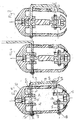
- a loading assembly according to a first embodiment of the present invention and as depicted in Figure 1 to 7 of the accompanying drawings comprises two parts: an upper part comprising an outer body 10 and a lower part comprising an inner body 12. Each of these comprises means to keep captive a nut such that by introduction of a threaded rod (not shown) or similar the respective part may be introduced into the load path.
- the outer body 10 is of the form of a generally planar frame surrounding an interior 30. It is to be mounted vertically and is elongate in a vertical direction. It comprises, at its top end, a suspension hole 14 in which nut 16 is held captive by circlip 18 held in circumferential groove 20. Accordingly, a rod may be introduced from above the outer body such that the outer body 10 and hence the assembly may be suspended from an anchor point.
- a rod may be introduced from above the outer body such that the outer body 10 and hence the assembly may be suspended from an anchor point.
- two parallel vertical forks 34 hereinafter referred to as the "upper" forks 34. Each fork has an elongate hole 52 formed through it.
- An opening 22 at the bottom of the outer body 10 allows connection of a load to the inner body, which is contained within the interior 30 of the outer body 10.
- the walls of the outer body 10 surrounding the lower opening 22 define a section of the surface of a sphere, with a centre point 36 between the two forks 34. As will be described hereinbelow, this enables a load to swing about the centre point 36 as is likely will happen with a suspended load.
- the inner body 12 is of the form of a horizontal bridge portion 24 with two parallel spaced apart forks 26. These forks shall hereinafter be referred to as the "lower" forks 26.
- the inner body 12 has in the bridge portion 24 a nut 28 again held captive by a circlip 30 in circumferential groove 32. In this case, a rod may be introduced below such that a load may be suspended from the inner body.
- the lower forks 26 each have a hole 40 passing through them.
- Inner body 12 is held secure to outer body 10 by means of a lower engagement member of the form of a lower shaft passing through one of the fork holes 40 and a lower transit hole 42 in the outer body. Washers and split pins (depicted as 46) hold the lower shaft in place.
- An upper engagement member of the form of a cranked upper shaft 58 is also provided.
- the upper shaft 58 has a first arm 54, which rests in first 48 and second 50 upper shaft holes on opposite sides of the walls of the upper body.
- the upper shaft 58 also rests in the elongate holes 52 in the upper forks 34. Accordingly, it is necessary that these holes lie along a common, and in this case horizontal, axis.
- the first arm 54 of the upper shaft has a cranked portion 56, which in use and in this transit position, sits between the upper forks and is displaced vertically upwards with respect to the axis of the first arm 54.
- the second upper shaft hole 50 and the elongate holes 52 in the upper forks 34 are necessarily elongate due to the necessity to allow insertion of the upper shaft 58 and more particularly the cranked portion 56 through the second upper shaft hole 50.
- the end of the first arm 54 that passes through first hole 48 is secured by means of split pin and washer 62.
- the cranked upper shaft 58 has a second arm 60, which extends perpendicularly from the end of the first arm normally adjacent to the second upper shaft hole 50. In the transit position, this second arm 60 is secured to the upper body by means of a screw 64 passing through second arm hole 66 and into captive nut 68 retained within outer body 10.
- the captive nut 68 is positioned so that, in the transit position, the second arm 60 is generally vertical.
- the load assembly comprises an S-beam load cell 72 as are well know in the art.
- the load cell 72 is of the form of an S-shaped beam, with recesses 76 in the crooks of the S.
- a thinned out section 78 is provided in the centre of the S, in which the thickness in the plane of the S is greatly reduced.
- strain gauges are mounted, electrically connected to form a bridge.
- the thinned out section 78 is then welded over to provide the strain gauges with protection from the elements. Electrical connections to the strain gauges are provided by means of a cable 80.
- This type of load cell 72 is well known in the art and is used due to its reliability and predictability.
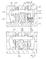
- Recesses 82 are provided in the top and bottom of the S of the load cell into which loading adaptors 84a, 84b are inserted to form the assembly.
- the loading adaptors (depicted as 84 in figures 2a and 2b) each comprise a body section 86 having aperture 90.
- the aperture 90 has curved walls, which means the adaptor 84 is allowed to rock about a shaft introduced into the aperture 90 about all three axes.
- the adapter 84 also has a plug 88 depending from it, whereby it is mated to load cell 72.
- the user wishing to install the load cell invention of this embodiment installs the assembly in the load path in the above-described transit position by screwing threaded rods, connected to an anchor point and to the load to be suspended, into the captive nuts 16, 28 in the upper 10 and lower 12 bodies respectively.
- the user then removes upper 58 and lower 44 shafts, and offers the top loading adaptor 84a of the load cell assembly 70 up to the upper forks 34.
- Upper shaft 58 is replaced in the upper body 10 in the position shown in figure 6. In this "inoperative" position, the upper shaft is replaced in the upper body rotated by 180 degrees about the axis of the first arm 54 relative to the transit position.
- the cranked portion 56 now lies vertically below the axis of the first arm 54, and engages the recess 90 of the upper loading adaptor 84a.
- the inner body 12 is then attached to the lower loading adaptor 84b by means of lower shaft 44 passing through lower forks 26 and recess 90 of lower loading adaptor 84b.
- the load cell 72 is not under load as the lower body 12 is resting on the lower interior surface of the outer body.
- the assembly is now in the position shown in figure 6.
- the load assembly may be necessary to remove the load cell assembly 70, for example for maintenance of the load cell 72 or if the load cell 72 fails.
- the screw 64 is removed and the second arm 60 rotated through 180 degrees to the non-working position depicted in figure 6.
- the load acts through the two bodies 10, 12 and not through the load cell assembly 70.
- Load cell assembly 70 accordingly can be removed and replaced as necessary and then the second arm 60 rotated back 180 degrees to the working position and secured with screw 64.
- the load cell assembly 70 separates (for example, if the load cell 72 breaks) in some way, the inner body 12 will no longer be held by the load cell assembly 70 and will fall until it hits-the outer body 10. Hence, the load will simply be transferred from being held by the load cell assembly 70 being supported by the outer body 10. This removes the need for a separate safety strap.
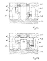
- FIG. 8 to 13 of the accompanying drawings A second embodiment of the invention is depicted in Figures 8 to 13 of the accompanying drawings. Similar features to those of the first embodiment have been given the same reference indices raised by 100.
- the load cell assembly shown is used in compression, with the assembly supporting a load above a surface such as a floor.
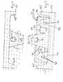
- the assembly comprises a lower part 112, securable to a floor, and an upper part 110 to which a load can be secured. Both parts have a body section of the form of a plate, which can be fixed to the load or the floor as appropriate.
- Two sets of forks 126 depend upwards from lower portion 112 and each carry a shaft 140 between the forks of each set. These shafts 140 engage and support either end of a shear beam load cell 170. This is of the form of a bar mounted at either end, with two thinned out portions 178 between the mounting points. Strain gauges (not shown) are mounted on these thinned out sections 178. Electrical connection is made to these strain gauges is made by cable 180 to the appropriate measurement apparatus. A groove 171 is provided at the middle of the top surface of the load cell 170 on which the load is applied as described below.
- the upper part 110 also has a set of forks 111 depending from its body section. Each fork is provided with an aperture 113 through which a cranked shaft 154 may be introduced as described below.
- the apertures 113 are spaced slightly from the body section such that the top of the aperture is lower than the bottom of the plate of the body section.
- the upper part 110 is mounted on the load cell by means of upper engagement member 158.
- This is of the form of a horizontal cranked shaft 154 having a handle portion 160 in a similar manner to the first embodiment.
- the load cell engages the upper engagement member 158 at a central cranked portion 156 of the cranked bar 154.
- This central cranked portion 156 also engages the body section of the upper part 110.
- the outer, uncranked, portions 157 further engage the upper part 110 at the top of each aperture 113. Any load applied to the upper part 110, for example by placing a vessel on top of the upper part 110, will therefore pass through the upper part, the upper engagement member 158, the load cell 170 and finally the lower part 112.
- the upper engagement mean further comprises a handle 160, which can be secured to the upper part 110 by means of a bolt 164 and a captive nut 168 in the same manner as in the first embodiment.
- Each of the upper and lower parts 110, 112 have a set of support posts 143, 145 at each corner thereof, depending from the relevant part towards a matching set of support posts 145, 143 of the other part. In normal use, ( Figure 8 of the accompanying drawings) these do not contact one another and so have no effect on the operation of the assembly.
- the upper engagement member can then be rotated back to the operative position ( Figure 8 of the accompanying drawings) such that the lower part 112 supports the upper part 110 through the spacers 147.
- the load cell 170, the upper engagement member 158 and the lower shafts 140 may therefore safely be removed, to leave the assembly in the position of Figure 10a of the accompanying drawings.
- the upper engagement member 158 can then be reintroduced into the assembly ( Figure 10b of the accompanying drawings). This ensures that the two parts of the assembly cannot separate due to upwards forces on the upper part. This a further safety feature, as the load may be restrained from toppling etc. by the assembly.
- the upper body 110 will no longer be held by the load cell 170 and will fall until the upper supports 143 hit the lower supports 145. Hence, the load will simply be transferred from being held by the load cell 170 to being supported by the lower body 112 through the supports 143, 145. This removes the need for a separate safety support.
Landscapes
- Physics & Mathematics (AREA)
- General Physics & Mathematics (AREA)
- Measurement Of Force In General (AREA)
- Load-Engaging Elements For Cranes (AREA)
Applications Claiming Priority (2)
| Application Number | Priority Date | Filing Date | Title |
|---|---|---|---|
| GB0216175 | 2002-07-12 | ||
| GBGB0216175.0A GB0216175D0 (en) | 2002-07-12 | 2002-07-12 | Load assembly |
Publications (2)
| Publication Number | Publication Date |
|---|---|
| EP1380824A2 true EP1380824A2 (fr) | 2004-01-14 |
| EP1380824A3 EP1380824A3 (fr) | 2004-01-21 |
Family
ID=9940305
Family Applications (1)
| Application Number | Title | Priority Date | Filing Date |
|---|---|---|---|
| EP20030254393 Withdrawn EP1380824A3 (fr) | 2002-07-12 | 2003-07-11 | Arrangement pour mesurer une charge |
Country Status (3)
| Country | Link |
|---|---|
| US (1) | US7096742B2 (fr) |
| EP (1) | EP1380824A3 (fr) |
| GB (1) | GB0216175D0 (fr) |
Families Citing this family (3)
| Publication number | Priority date | Publication date | Assignee | Title |
|---|---|---|---|---|
| US7644628B2 (en) * | 2005-12-16 | 2010-01-12 | Loadstar Sensors, Inc. | Resistive force sensing device and method with an advanced communication interface |
| US7750253B2 (en) | 2006-02-21 | 2010-07-06 | New Enterprise Stone And Lime Co. | Conveyor belt scale system |
| EP2857807B1 (fr) * | 2013-10-04 | 2020-09-16 | Vishay Advanced Technologies Ltd. | balance suspendue |
Citations (3)
| Publication number | Priority date | Publication date | Assignee | Title |
|---|---|---|---|---|
| US3908772A (en) | 1973-09-28 | 1975-09-30 | Sca Development Ab | Measuring device |
| US5591943A (en) | 1994-06-10 | 1997-01-07 | Cheng; Liang-Chieh | Weight-sensing member for an electrical suspension weigher |
| US5745042A (en) | 1993-02-03 | 1998-04-28 | Pratt; Hugh Michael | Load insulator |
Family Cites Families (11)
| Publication number | Priority date | Publication date | Assignee | Title |
|---|---|---|---|---|
| US3646512A (en) * | 1970-09-01 | 1972-02-29 | George J Borgstede | Vehicle trailer bed overload indicating system |
| GB1487396A (en) | 1975-07-15 | 1977-09-28 | Davy Loewy Ltd | Tensiometers |
| US4533009A (en) * | 1984-04-05 | 1985-08-06 | Evans David L | Lifting and transporting devices |
| GB2208940A (en) | 1987-08-21 | 1989-04-19 | Thames Side Scient Co Ltd | Load cell |
| US4862740A (en) * | 1989-02-15 | 1989-09-05 | The Mead Corporation | Glue bond tester |
| US5273333A (en) * | 1993-02-22 | 1993-12-28 | Columbia Helicopters, Inc. | Load hook assembly for multiple loads and method of load transport |
| CA2096761C (fr) | 1993-05-21 | 1995-07-04 | William P. Strelioff | Balance mobile |
| US5593113A (en) * | 1995-02-06 | 1997-01-14 | Cox; Donald P. | Methods and apparatus for selectively attaching and releasing multiple payloads suspended from an aircraft |
| US5744955A (en) * | 1995-08-02 | 1998-04-28 | Booker; James R. | Apparatus and method of detecting loss of cross-sectional area of magnetic metallic strength members used in conductors such as aluminum conductor steel reinforced (ACSR) conductors |
| GB9808768D0 (en) | 1998-04-25 | 1998-06-24 | Nova Weigh Limited | Improved weighing assembly |
| IT247843Y1 (it) * | 1999-04-16 | 2002-09-10 | Firenze Ind Fototecnica | Un dispositivo di sospensione di carichi,in specie per apparecchiilluminatori per studi fotografici o televisivi. |
-
2002
- 2002-07-12 GB GBGB0216175.0A patent/GB0216175D0/en not_active Ceased
-
2003
- 2003-07-10 US US10/618,435 patent/US7096742B2/en not_active Expired - Lifetime
- 2003-07-11 EP EP20030254393 patent/EP1380824A3/fr not_active Withdrawn
Patent Citations (3)
| Publication number | Priority date | Publication date | Assignee | Title |
|---|---|---|---|---|
| US3908772A (en) | 1973-09-28 | 1975-09-30 | Sca Development Ab | Measuring device |
| US5745042A (en) | 1993-02-03 | 1998-04-28 | Pratt; Hugh Michael | Load insulator |
| US5591943A (en) | 1994-06-10 | 1997-01-07 | Cheng; Liang-Chieh | Weight-sensing member for an electrical suspension weigher |
Also Published As
| Publication number | Publication date |
|---|---|
| EP1380824A3 (fr) | 2004-01-21 |
| US20040144185A1 (en) | 2004-07-29 |
| GB0216175D0 (en) | 2002-08-21 |
| US7096742B2 (en) | 2006-08-29 |
Similar Documents
| Publication | Publication Date | Title |
|---|---|---|
| US11740120B2 (en) | Method and apparatus to monitor a reservoir or a structure | |
| US5600104A (en) | Load cell having reduced sensitivity to non-symmetrical beam loading | |
| CN201047775Y (zh) | 称重模块 | |
| US5707168A (en) | Heavy object lifting connector device | |
| US20030102170A1 (en) | Standard attachment fittings for wire rope and chain enhanced to also perform load weighing functions | |
| US12385773B2 (en) | System to measure the weight applied by a supporting member of a structure and method of installation thereof | |
| EP0952436A2 (fr) | Montage de cellules de charge | |
| US20230013829A1 (en) | Apparatus, system and method for lifting a conveyor belt | |
| US4828055A (en) | Weighbridge with pivotal supporting system | |
| US7096742B2 (en) | Load support assembly and method of using same | |
| EP2643670B1 (fr) | Agencement et procédé pour tester la capacité à supporter une charge d'un appareil de levage | |
| CN206710195U (zh) | 一种用于预应力混凝土梁四点弯曲的疲劳加载装置 | |
| CN110388975A (zh) | 称重模块 | |
| CN111356906B (zh) | 负荷传感器提离保护装置 | |
| CN109520606B (zh) | 称重装置及称重方法 | |
| US4585092A (en) | Device for setting the attitude and the measuring height of the body of a vehicle to be checked on a surface plate, elevator, stays or other means without subjecting it to any warping stress | |
| CA1144195A (fr) | Bloc-etalon de pesage | |
| EP1666853A2 (fr) | Dispositif pour peser une charge | |
| JPH11211543A (ja) | ロードセルの過負荷防止装置 | |
| CN223466179U (zh) | 电磁阀线圈检查存放工装 | |
| KR101723023B1 (ko) | 인양장비 안전성 검사용 시험장치 및 방법 | |
| WO2005029026A1 (fr) | Procede d'appui d'un support de charge | |
| CN218222695U (zh) | 一种轴的连接机构 | |
| WO2007083125A1 (fr) | Ensemble de montage pour capteurs de force | |
| JPH0632581Y2 (ja) | ピン支持型ロードセル |
Legal Events
| Date | Code | Title | Description |
|---|---|---|---|
| PUAI | Public reference made under article 153(3) epc to a published international application that has entered the european phase |
Free format text: ORIGINAL CODE: 0009012 |
|
| PUAL | Search report despatched |
Free format text: ORIGINAL CODE: 0009013 |
|
| AK | Designated contracting states |
Kind code of ref document: A2 Designated state(s): AT BE BG CH CY CZ DE DK EE ES FI FR GB GR HU IE IT LI LU MC NL PT RO SE SI SK TR |
|
| AX | Request for extension of the european patent |
Extension state: AL LT LV MK |
|
| AK | Designated contracting states |
Kind code of ref document: A3 Designated state(s): AT BE BG CH CY CZ DE DK EE ES FI FR GB GR HU IE IT LI LU MC NL PT RO SE SI SK TR |
|
| AX | Request for extension of the european patent |
Extension state: AL LT LV MK |
|
| 17P | Request for examination filed |
Effective date: 20040714 |
|
| AKX | Designation fees paid |
Designated state(s): AT BE BG CH CY CZ DE DK EE ES FI FR GB GR HU IE IT LI LU MC NL PT RO SE SI SK TR |
|
| 17Q | First examination report despatched |
Effective date: 20070529 |
|
| RAP1 | Party data changed (applicant data changed or rights of an application transferred) |
Owner name: THAMES SIDE SENSORS LIMITED |
|
| GRAP | Despatch of communication of intention to grant a patent |
Free format text: ORIGINAL CODE: EPIDOSNIGR1 |
|
| INTG | Intention to grant announced |
Effective date: 20171016 |
|
| RIN1 | Information on inventor provided before grant (corrected) |
Inventor name: BAILEY, MICHAEL ANTHONY |
|
| STAA | Information on the status of an ep patent application or granted ep patent |
Free format text: STATUS: THE APPLICATION IS DEEMED TO BE WITHDRAWN |
|
| 18D | Application deemed to be withdrawn |
Effective date: 20180227 |
|
| RIC1 | Information provided on ipc code assigned before grant |
Ipc: G01G 21/23 20060101ALI20031120BHEP Ipc: G01L 1/22 20060101AFI20031120BHEP |