EP1380954B1 - Système informatique et procédé de traitement d'informations - Google Patents
Système informatique et procédé de traitement d'informations Download PDFInfo
- Publication number
- EP1380954B1 EP1380954B1 EP03014600A EP03014600A EP1380954B1 EP 1380954 B1 EP1380954 B1 EP 1380954B1 EP 03014600 A EP03014600 A EP 03014600A EP 03014600 A EP03014600 A EP 03014600A EP 1380954 B1 EP1380954 B1 EP 1380954B1
- Authority
- EP
- European Patent Office
- Prior art keywords
- data
- processor
- input
- main processor
- output unit
- Prior art date
- Legal status (The legal status is an assumption and is not a legal conclusion. Google has not performed a legal analysis and makes no representation as to the accuracy of the status listed.)
- Expired - Lifetime
Links
Images


Classifications
-
- G—PHYSICS
- G06—COMPUTING OR CALCULATING; COUNTING
- G06F—ELECTRIC DIGITAL DATA PROCESSING
- G06F11/00—Error detection; Error correction; Monitoring
- G06F11/22—Detection or location of defective computer hardware by testing during standby operation or during idle time, e.g. start-up testing
- G06F11/26—Functional testing
- G06F11/273—Tester hardware, i.e. output processing circuits
- G06F11/2733—Test interface between tester and unit under test
-
- G—PHYSICS
- G06—COMPUTING OR CALCULATING; COUNTING
- G06F—ELECTRIC DIGITAL DATA PROCESSING
- G06F13/00—Interconnection of, or transfer of information or other signals between, memories, input/output devices or central processing units
- G06F13/38—Information transfer, e.g. on bus
- G06F13/40—Bus structure
- G06F13/4004—Coupling between buses
- G06F13/4022—Coupling between buses using switching circuits, e.g. switching matrix, connection or expansion network
Definitions
- the present invention relates to a computer system and a data processing method which is adapted thereto, and, more particularly, to a computer system with a diagnosis capability, which has a simple system architecture, and a data processing method to be adapted thereto.
- SVP service processor
- the SVP is, for example, a so-called sub system independent of the computer system and is used in, for example, failure diagnosis of hardware.
- the SVP is connected to an input/output (I/O) unit located outside the computer system and receives an instruction to diagnose, for example, the operational status of the hardware of the computer system from the I/O unit.
- the SVP also transmits information representing diagnosis results to the I/O unit in accordance with an instruction from the I/O unit.
- an I/O unit (console for the SVP) which gives an instruction to the SVP is connected to an SVP-equipped computer system.
- an I/O unit (console for the main processor) which inputs an instruction to the main processor is connected to the computer system.
- the connection of plural I/O units has made the system architecture of conventional computer system relatively complex.
- the complex system architecture is particularly noticeable in a multi-processor computer system having a plurality of main processors.
- a multi-processor computer system is connected with consoles for the individual main processors in addition to a console for the SVP. Because the main-processor consoles were needed by the number of the main processors, the system architecture was more complicated.
- a computer system which has overcome the complexity of the system architecture is disclosed in, for example, US 5 812 825 or JP-A-9-114789.
- a single I/O unit main-processor console
- EP 0 380 851 A2 relates to modular crossbar interconnections in a digital computer for efficiently handling data transactions between various system units (CPUs), I/O units and main memory units in a multi-processor system, the system units are linked via a plurality of expandable crossbar modules each providing a set of interconnections between the sets of input and output nodes, with each output being defined in terms of only one input.
- a single console or SVP can be connected to all CPUs.
- the invention specifically addresses the problem of interfacing a single SVP with a controller allowing to communicate with one or more main processors.
- a computer system comprises at least one main processor (10); a sub processor (30) connected to an input/output unit (2) which is operated by an operator; and a crossbar switch (20), connected to the at least one main processor (10) and the sub processor (30), for transferring data between the main processor (10) and the sub processor (30), the crossbar switch (20) including a diagnosis section (21) which diagnoses a failure in the main processor (10) in accordance with a command input from the input/output unit (2) and given to the sub processor (30).
- the diagnosis section (21) is capable of receiving data to be transmitted to the main processor (10) from the input/output unit (2) via the sub processor (30) and causing the main processor (10) to read the data, and receiving data to be transmitted to the input/output unit (2) from the main processor (10) and transmitting the data to the input/output unit (2) via the sub processor (30).
- the sub processor etc. executes a failure diagnosis in accordance with an instruction input from the input/output unit.
- Data to be transmitted to the main processor is transmitted to the main processor from the input/output unit via the crossbar switch, the sub processor and so forth and the main processor executes a predetermined process based on the data.
- Data to be transmitted to the input/output unit is transmitted to the input/output unit from the main processor via the crossbar switch, the sub processor and so forth. It is therefore unnecessary to separately connect an input/output unit for the sub processor and an input/output unit for the main processor to the computer system, making is possible to reduce the number of input/output units to connect to the computer system.
- the computer system therefore has a simple system architecture.
- the diagnosis section (21) may include a serial controller (22) having a first memory section (23) where data to be transmitted to the input/output unit (2) from the at least one main processor (10) is written by the main processor (10), and a second memory section (24) where data to be transmitted to the main processor (10) from the input/output unit (2) is written by the sub processor (30).
- a first address for allowing the at least one main processor (10) to write data in the first memory section (23) and a second address for allowing the sub processor (30) to write data in the second memory section (24) may be allocated to the serial controller (22).
- the serial controller (22) may give an instruction to read a memory content from the first memory section (23) to the sub processor (30) when data is written in the first memory section (23) by the at least one main processor (10), and give a permission for interruption to the sub processor (30) when a request to write data into the second memory section (24) has been made by the sub processor (30) and is interruptible.
- the diagnosis section (21) may further include at least one register which stores data representing a result of a failure diagnosis, and the sub processor (30) may read the data representing the result of the failure diagnosis from the register in accordance with an instruction given from the input/output unit (2) and send the read-out data to the input/output unit (2).
- the diagnosis section (21) may include a plurality of serial controllers (22a, 22b, 22c, 22d) respectively corresponding to a plurality of main processors (10a, 10b, 10c, 10d), and the sub processor (30) may write data to be transmitted to one of the plurality of main processors (10a, 10b, 10c, 10d), which is input from the input/output unit (2), in the second memory section of that serial controller (22a, 22b, 22c, 22d) which corresponds to the main processor (10) where the data is to be transmitted by designating an address of that serial controller (22a, 22b, 22c, 22d).
- the input/output unit (2) may give an instruction to the sub processor (30), allow the sub processor (30) to execute a process based on the instruction, receive data representing a result of the process from the sub processor (30), give an instruction to the at least one main processor (10) via the sub processor (30) and the diagnosis section (21), allow the main processor (10) to execute a process based on that instruction, receive data representing a result of that process via the diagnosis section (21) and the sub processor (30), so that the input/output unit (2) serves as a common console for the sub processor (10) and the main processor (30).
- a data processing method for use in a computer system comprising at least one main processor (10), a sub processor (30) connected to an input/output unit (2) which is operated by an operator, and a diagnosis section (21) which is connected to the main processor (30) and the sub processor (30) and diagnoses a failure in the main processor (30) together with the sub processor (30) in accordance with a command given from the input/output unit (2).
- the method comprises the steps of: transmitting first data to be transmitted to the at least one main processor (10) to the sub processor (30) from the input/output unit (2), allowing the sub processor (30) to store the transmitted first data in the diagnosis section (21), allowing the main processor (10) to read the first data stored in the diagnosis section (21) and allowing the main processor (10) to execute a process based on the read-out first data; and allowing the main processor (10) to store second data to be transmitted to the input/output unit (2) in the diagnosis section (21), allowing the sub processor (30) to read the stored second data from the diagnosis section (21) and transmit the second data to the input/output unit (2) and allowing the input/output unit (2) to display contents of said transmitted second data.
- the sub processor or the like executes a failure diagnosis in accordance with an instruction input from the input/output unit.
- First data to be transmitted to the main processor is transmitted to the main processor from the input/output unit via the sub processor, the diagnosis section and so forth.
- Second data to be transmitted to the input/output unit is transmitted to the input/output unit from the main processor via the diagnosis section, the sub processor and so forth.
- This can allow the input/output unit to serve as not only a console for the sub processor but also a console for the main processor. It is therefore unnecessary to separately connect a console for the sub processor and a console for the main processor to the computer system, making is possible to reduce the number of consoles (input/output units) to connect to the computer system. The reduction in the quantity of input/output units to connect to the computer system can make the structure of the computer system simpler.
- the diagnosis section (21) may include a serial controller (22) having a first memory section (23) for storing the first data to be transmitted to the input/output unit (2) from the at least one main processor (10), and a second memory section (24) for storing the second data to be transmitted to the main processor (10) from the input/output unit (2), and a first address which is designated by the at least one main processor (10) and a second address which is designated by the sub processor (30) may be allocated to the serial controller (22).
- a serial controller (22) having a first memory section (23) for storing the first data to be transmitted to the input/output unit (2) from the at least one main processor (10), and a second memory section (24) for storing the second data to be transmitted to the main processor (10) from the input/output unit (2), and a first address which is designated by the at least one main processor (10) and a second address which is designated by the sub processor (30) may be allocated to the serial controller (22).
- Serial controllers (22a, 22b, 22c, 22d) respectively corresponding to plurality of main processors (10a, 10b, 10c, 10d) may be provided in the diagnosis section (21), the sub processor (30) may store the second data to be transmitted to one of the plurality of main processors (10a, 10b, 10c, 10d) in that serial controller (22a, 22b, 22c, 22d) which corresponds to the main processor (10a, 10b, 10c, 10d) where the second data is to be transmitted, and the main processor (10a, 10b, 10c, 10d) where the second data is to be transmitted reads the second data stored in that serial controller (22a, 22b, 22c, 22d) and executes a process based on the second data.
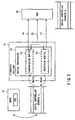
- a computer system 1 As shown in Fig. 1, a computer system 1 according to the embodiment comprises a node 10, a crossbar switch 20, a service processor (SVP) 30 and an input/output (I/O) device 40.
- An input/output (I/O) unit 2 is connected to the computer system 1 via the SVP 30.
- the I/O unit 2 will be discussed first.
- the I/O unit 2 is constituted by a general-purpose computer equipped with peripheral devices, such as a keyboard, a mouse and a display.
- the I/O unit 2 instructs, for example, the SVP 30 to execute a failure diagnosis of the hardware of the computer system 1 or receives information representing failure diagnosis results from the SVP 30. That is, the I/O unit 2 serves as a console for the SVP (hereinafter simply referred to as "SVP console").
- the I/O unit 2 By running an emulation program stored in a memory or the like (not shown), the I/O unit 2 also serves as a console for the node 10 of the computer system 1. For instance, the I/O unit 2 provides an operator with interaction means with an operating system (OS) which operates the computer system 1 and transmits various instructions for the node 10 to the computer system 1. The I/O unit 2 receives various kinds of data transmitted from the computer system 1.
- OS operating system
- the node 10 is constituted by, for example, a CPU (Central Processing Unit).
- the node 10 executes various processes under the control of the OS.
- the node 10 sends data to the I/O device 40 and receives data from the I/O device 40, via the crossbar switch 20 in both events. Further, the node 10 receives an instruction from the I/O unit 2 that is serving as the console for the node 10 and sends data representing the results of a predetermined process executed according to the instruction, via the crossbar switch 20 and SVP 30 in both events.
- Console input data for example, a command, etc.
- console output data for example, an error message of OS, etc.
- the crossbar switch 20 serves as an internal communication mechanism which automatically selects a communication path at the time when communication is made between the node 10 and the I/O device 40 and between the node 10 and the SVP 30.
- the crossbar switch 20 has a diagnosis section 21.
- the diagnosis section 21 together with the node 10, the SVP 30 and so forth, diagnoses a failure in the hardware of the computer system 1.
- the diagnosis section 21 has at least one register (hereinafter, "diagnosis register") (not shown) which stores data representing the results of the failure diagnosis and an instruction (command) for the failure diagnosis.
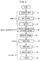
- the diagnosis section 21 further has a serial controller 22.
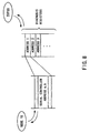
- the serial controller 22 exchanges console input/output data between the node 10 and the SVP 30, as shown in Fig. 2.
- a serial controller address a and a serial controller address b are allocated to the serial controller 22.
- both the serial controller addresses a and b are part of the address which is allocated to one of the diagnosis registers.
- the serial controller address a is designated by the node 10 when the node 10 sends (writes) console output data to the serial controller 22 or receives (reads) console input data from the serial controller 22.
- the serial controller address b is designated by the SVP 30 when the SVP 30 sends console input data to the serial controller 22 via a diagnosis path 25 or receives console output data from the serial controller 22.
- the serial controller 22 has a transmission buffer 23 for storing console output data sent from the node 10 and a reception buffer 24 for storing console input data sent from the SVP 30.
- the transmission buffer 23 and the reception buffer 24 are constituted by, for example, a ring buffer having a predetermined capacity.
- the serial controller 22 receives the console output data sent from the node 10 and stores the data into the transmission buffer 23.
- the serial controller 22 also receives the console input data sent from the SVP 30 via the diagnosis path 25 and stores the data in the reception buffer 24.
- the serial controller 22 sends a signal (transmission interrupt signal) to the SVP 30 via a transmission interrupt signal line 26 and request the SVP 30 to read the console output data stored in the transmission buffer 23.
- the serial controller 22 In response to the request to write the console input data in the reception buffer 24 from the SVP 30, the serial controller 22 sends a signal (reception interrupt signal) via a reception interrupt signal line 27 when the console input data is storable in the reception buffer 24. This notifies the SVP 30 that reception and storage of the console input data are possible.
- the SVP 30 stores an instruction (command) for a failure diagnosis in the diagnosis register of the diagnosis section 21 via the diagnosis path 25.
- the SVP 30 reads information representing the results of the failure diagnosis stored in the diagnosis register via the diagnosis path 25 from the diagnosis register.
- the SVP 30 receives the console input data sent from the I/O unit 2 and writes the data in the reception buffer 24 in the serial controller 22. Further, the SVP 30 reads the console output data written in the transmission buffer 23 by the node 10 and sends the data to the I/O unit 2.
- the SVP 30 first receives a transmission interrupt signal from the serial controller 22 via the transmission interrupt signal line 26 and accepts a request from the serial controller 22 to read console output data stored in the transmission buffer 23. In response to the request, the SVP 30 designates the serial controller address b and reads the console output data from the transmission buffer 23.
- the SVP 30 first discriminates whether the reception interrupt signal has been output from the serial controller 22 or not. Accordingly, the SVP 30 discriminates whether or not the serial controller 22 can store console input data in the reception buffer 24. When having discriminated that the reception interrupt signal has been output from the serial controller 22 via the reception interrupt signal line 27, the SVP 30 designates the serial controller address b and stores the console input data in the reception buffer 24.
- the I/O device 40 shown in Fig. 1 is comprised of a peripheral device, such as a magnetic drive unit or a printer.
- the I/O device 40 operates according to the control of the node 10.
- the node 10 carries out data transmission and reception to each I/O device 40.
- the node 10 executes a predetermined process under the control of the OS and generates data representing the results of the process (console output data: for example, data representing an error message of OS) (step S1).
- the node 10 designates the serial controller address a and stores the generated data (console output data) in the transmission buffer 23 in the serial controller 22 (step S2).
- the node 10 notifies the serial controller 22 of that event (step S3).
- the serial controller 22 sends the transmission interrupt signal to the SVP 30 via the transmission interrupt signal line 26 to instruct reading of data stored in the transmission buffer 23 (step S4).
- the SVP 30 receives the transmission interrupt signal (step S5). In response to the instruction from the serial controller 22, the SVP 30 designates the serial controller address b and reads the data from the transmission buffer 23 (step S6). Then, the SVP 30 sends the data to the I/O unit 2 (step S7).
- the I/O unit 2 receives the data (step S8). Then, the I/O unit 2 displays (outputs) the contents of the received data as console data for the computer system 1 on the display (step S9).
- console input data e.g., a command
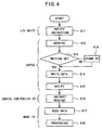
- console input data (a predetermined instruction to the node 10) is transmitted to the SVP 30 from the I/O unit 2 (step S11)
- the SVP 30 receives the data (step S12).
- the SVP 30 request the serial controller 22 to write data (console input data) in the reception buffer 24.
- the serial controller 22 sends the reception interrupt signal to the SVP 30 via the reception interrupt signal line 27 when data writing (interrupt) is possible.
- data writing is not possible, on the other hand, the serial controller 22 does not send the reception interrupt signal to the SVP 30.
- the SVP 30 discriminates whether or not the serial controller 22 is in a data receivable state based on the presence/absence of the reception interrupt signal (step S13).
- the SVP 30 designates the serial controller address b and stores the data received from the I/O unit 2 in the reception buffer 24 (step S14).
- the SVP 30 notifies the serial controller 22 of that event (step S15).
- the serial controller 22 instructs the node 10 to read data stored in the reception buffer 24 (step S16).
- the node 10 designates the serial controller address a and reads data stored in the reception buffer 24 as input data from the I/O unit 2(step S17). Then, the node 10 executes a process based on the read-out data (step S18).
- step S13 When having discriminated in step S13 that the reception interrupt signal has not been sent from the serial controller 22 (step S13: NO), the SVP 30 stands by until it receives the reception interrupt signal from the serial controller 22 (step S19). After reception of the reception interrupt signal, the SVP 30 proceeds to step S14.
- diagnosis section 21 and the SVP 30 for diagnosing a failure in the node 10 or the like are provided between the node 10 and the I/O unit 2 in the computer system 1 according to the embodiment.
- the diagnosis section 21 has the serial controller 22 which exchanges console output data and console input data between the node 10 and the SVP 30.
- the I/O unit 2 connected to the SVP 30 can give the node 10 an instruction to execute various processes using the SVP 30 and the serial controller 22 as well as can give the SVP 30 or the like an instruction for a failure diagnosis. Therefore, it is unnecessary to separately connect an I/O unit for inputting an instruction to the SVP 30 or the like and an I/O unit for inputting an instruction to the node 10 to the computer system 1 according to the embodiment.
- the single I/O unit 2 connected to the computer system 1 can serve as both the SVP console and the main-processor console. The reduction in the number of I/O units 2 to connect to the computer system 1 makes the system architecture of the computer system simpler.
- the computer system 1 has a single node 10 as one example.
- the computer system 1 has a plurality of nodes 10 for the purpose of, for example, improving the processing speed and the I/O unit 2 is connected to the computer system 1 for each node 10.
- the computer system 1 has only to be equipped with a plurality of serial controllers 22 corresponding to the plural nodes 10.
- the computer system 1 has a node 10a, node 10b, node 10c and node 10d.
- the nodes 10a to 10d are all connected to the crossbar switch 20.
- the diagnosis section 21 in the crossbar switch 20 has serial controllers 22a, 22b, 22c and 22d.
- the serial controllers 22a, 22b, 22c and 22d respectively correspond to the nodes 10a, 10b 10c and 10d.
- the serial controllers 22a, 22b, 22c and 22d are connected to the SVP 30 via transmission interrupt signal lines 26a, 26b, 26c and 26d and reception interrupt signal lines 27a, 27b, 27c and 27d, respectively.
- Serial controller addresses a1, a2, a3 and a4 and serial controller addresses b1, b2, b3 and b4 are respectively allocated to the serial controllers 22a, 22b, 22c and 22d.
- the addresses that the nodes 10a to 10d can designate are only those respectively allocated to the serial controllers 22a to 22d.
- the address that the node 10c can designate is the address (serial controller address a3) that is allocated to the serial controller 22c.
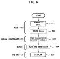
- the node 10c generates console output data directed to the I/O unit 2 (step S21).
- the node 10c designates the serial controller address a3 and writes the generated data in the transmission buffer of the serial controller 22c (step S22).
- the node 10c notifies the serial controller 22c of that event.
- the serial controller 22c sends the transmission interrupt signal to the SVP 30 via the transmission interrupt signal line 26c (step S23).
- the SVP 30 receives the transmission interrupt signal (step S24).
- the SVP 30 designates the serial controller address b3 to read data from the transmission buffer and sends the data to the I/O unit 2 (step S24).
- the I/O unit 2 receives the data and displays the contents of the data on the display (step S25).
- the I/O unit 2 sends console input data (command for the node 10) to the SVP 30 (S31).
- the SVP 30 receives the console input data and discriminates whether or not the reception interrupt signal is output from the serial controller 22c via the reception interrupt signal line 27c. That is, the SVP 30 discriminates whether or not the reception buffer of the serial controller 22c is in a data writable state (step S32). When having discriminated that the reception interrupt signal has been transmitted (step S32: YES), the SVP 30 designates the serial controller address b3 and writes data in the reception buffer of the serial controller 22c (step S33). When completing data writing, the SVP 30 notifies the serial controller 22c of that event.
- the serial controller 22c instructs the node 10c to read data from the reception buffer (step S34).
- the node 10c designates the serial controller address a3 and reads data from the reception buffer (step S35). Then, the node 10c processes the read data.
- step S32 When having discriminated in step S32 that the reception buffer is not in a data writable state (step S32: NO), the SVP 30 stands by until it receives the reception interrupt signal from the serial controller 22c. Upon reception of the reception interrupt signal, the SVP 30 proceeds to step S33.
- the computer system 1 has the serial controllers 22a, 22b, 22c and 22d respectively corresponding to the nodes 10a, 10b, 10c and 10d.
- This can allow the single I/O unit 2 and SVP 30 to send and receive console input/output data node by node without comprising a plurality of I/O units 2 or a plurality of SVPs 30.
- the invention is not limited to the above-described embodiments. Although the foregoing descriptions of the first and second embodiments have been given of the case, as an example, where the serial controller 22 intervenes to exchange data between the node 10 and the I/O unit 2, a parallel controller may intervene in data exchange in place of the serial controller 22.
Landscapes
- Engineering & Computer Science (AREA)
- General Engineering & Computer Science (AREA)
- Theoretical Computer Science (AREA)
- Physics & Mathematics (AREA)
- Computer Hardware Design (AREA)
- General Physics & Mathematics (AREA)
- Mathematical Physics (AREA)
- Quality & Reliability (AREA)
- Test And Diagnosis Of Digital Computers (AREA)
Claims (7)
- Système informatique caractérisé parce qu'il comprend :dans lequel ledit contrôleur (22)au moins un processeur principal (10) ;un sous-processeur (30) connecté à une unité d'entrée/sortie (2) qui est utilisée par un opérateur, etun commutateur à barres croisées (20), connecté audit au moins un processeur principal (10) et audit sous-processeur (30), pour transférer des données entre ledit processeur principal (10) et ledit sous-processeur (30), ledit commutateur à barres croisées (20) comprenant une section de diagnostic (21) qui diagnostique une défaillance dans ledit processeur principal (10) selon une entrée de commande de ladite unité d'entrée/sortie (2) et l'envoie audit sous-processeur (30),ladite section de diagnostic (21) étant capable de recevoir des données à transmettre audit processeur principal (10) depuis ladite unité d'entrée/sortie (2) via ledit sous-processeur (30) et d'amener ledit processeur principal (10) à lire lesdites données, et de recevoir les données à transmettre à ladite unité d'entrée/sortie (2) depuis ledit processeur principal (10) et de transmettre lesdites données à ladite unité d'entrée/sortie (2) via ledit sous-processeur (30), dans lequel ladite section de diagnostic (21) comprend, soit un contrôleur série (22), soit un contrôleur parallèle (22) ayant une première section de mémoire (23) où les données à transmettre à ladite unité d'entrée/sortie (2) depuis ledit au moins un processeur principal (10) sont écrites par ledit processeur principal (10) et une deuxième section de mémoire (24) où les données à transmettre audit processeur principal (10) depuis ladite unité d'entrée/sortie (2) sont écrites par ledit sous-processeur (30), et
envoie une instruction pour lire un contenu de mémoire de ladite première section de mémoire (23) audit sous-processeur (30) quand des données sont écrites dans ladite première section de mémoire (23) par ledit au moins un processeur principal (10), et
donne une autorisation d'interruption audit sous-processeur (30) quand une requête pour écrire des données dans ladite deuxième section de mémoire (24) a été effectuée par ledit sous-processeur (30) et ledit contrôleur peut être interrompu pour une écriture. - Système informatique selon la revendication 1, caractérisé par le fait qu'une première adresse est allouée audit contrôleur série pour permettre audit au moins un processeur principal (10) d'écrire des données dans ladite première section de mémoire (23) et une deuxième adresse pour permettre audit sous-processeur (30) d'écrire des données dans ladite deuxième section de mémoire (24).
- Système informatique selon la revendication 1 ou 2, dans lequel ladite section de diagnostic (21) comprend en outre au moins un registre qui stocke des données représentant un résultat d'un diagnostic de défaillance, et
ledit sous-processeur (30) lit lesdites données représentant ledit résultat dudit diagnostic de défaillance dans ledit registre selon une instruction envoyée depuis ladite unité d'entrée/sortie (2) et envoie lesdites données d'extraction à ladite unité d'entrée/sortie (2). - Système informatique selon la revendication 1, 2 ou 3, dans lequel ladite section de diagnostic (21) comprend une pluralité de contrôleurs série (22a, 22b, 22c, 22d) correspondant respectivement à une pluralité de processeurs principaux (10a, 10b, 10c, 10d), et
ledit sous-processeur (30) écrit les données à transmettre à un parmi ladite pluralité de processeurs principaux (10a, 10b, 10c, 10d), provenant de ladite unité d'entrée/sortie (2), dans ladite deuxième section de mémoire du contrôleur série (22a, 22b, 22c, 22d) qui correspond audit processeur principal (10) où lesdites données doivent être transmises en désignant une adresse de ce contrôleur série (22a, 22b, 22c, 22d). - Système informatique selon la revendication 1, 2, 3 ou 4, caractérisé en ce que ladite unité d'entrée/sortie (2) est configurée pour envoyer une instruction audit sous-processeur (30), permettre audit sous-processeur (30) d'exécuter un processus basé sur ladite instruction, recevoir des données représentant un résultat dudit processus depuis ledit sous-processeur (30), envoyer une instruction audit au moins un processeur principal (10) via ledit sous-processeur (30) et ladite section de diagnostic (21), permettre audit processeur principal (10) d'exécuter un processus basé sur cette instruction, recevoir des données représentant un résultat de ce processus via ladite section de diagnostic (21) et ledit sous-processeur (30), ladite unité d'entrée/sortie (2) servant de console commune audit processeur principal (10) et audit sous-processeur (30).
- Procédé de traitement de données adapté à une utilisation dans un système informatique comprenant au moins un processeur principal (10), un sous-processeur (30) connecté à une unité d'entrée/sortie (2) qui est actionnée par un opérateur, et une section de diagnostic (21) qui est connectée audit processeur principal (10) et audit sous-processeur (30) et diagnostique une défaillance dans ledit processeur principal (10) ainsi que dans ledit sous-processeur (30) selon une commande envoyée depuis ladite unité d'entrée/sortie (2), ledit procédé comprenant les étapes de :dans lequel ladite section de diagnostic (21) comprend, soit un contrôleur série (22), soit un contrôleur parallèle (22) ayant une première section de mémoire (23) pour stocker lesdites premières données à transmettre à ladite unité d'entrée/sortie (2) depuis ledit au moins un processeur principal (10), et une seconde section de mémoire (24) pour stocker lesdites secondes données à transmettre audit processeur principal (10) depuis ladite unité d'entrée/sortie (2) ettransmission des premières données à transmettre audit au moins un processeur principal (10) vers ledit sous-processeur (30) depuis ladite unité d'entrée/sortie (2), autorisation audit sous-processeur (30) de stocker lesdites premières données transmises dans ladite section de diagnostic (21), autorisation audit processeur principal (10) de lire lesdites premières données stockées dans ladite section de diagnostic (21), et autorisation audit processeur principal (10) d'exécuter un processus basé sur lesdites premières données d'extraction, etautorisation audit processeur principal (10) de stocker les secondes données à transmettre à ladite unité d'entrée/sortie (2) dans ladite section de diagnostic (21), autorisation audit sous-processeur (30) de lire lesdites secondes données stockées depuis ladite section de diagnostic (21) et de transmettre lesdites secondes données à ladite unité d'entrée/sortie (2) et autorisation à ladite unité d'entrée/sortie (2) d'afficher le contenu desdites secondes données transmises,
une première adresse qui est désignée par ledit au moins un processeur principal (10) et une seconde adresse qui est désignée par ledit sous-processeur (30) sont allouées audit contrôleur (22),
dans lequel ledit contrôleur (22)
envoie une instruction pour lire un contenu de mémoire de ladite première section de mémoire (23) vers ledit sous-processeur (30) quand les données sont écrites dans ladite première section de mémoire (23) par ledit au moins un processeur principal (10), et
envoie une autorisation d'interruption audit sous-processeur (30) quand une requête pour écrire des données dans ladite deuxième section de mémoire (24) a été effectuée par ledit sous-processeur (30) et ledit contrôleur peut être interrompu pour une écriture. - Procédé de traitement de données selon la revendication 6, caractérisé en ce que des contrôleurs série (22a, 22b, 22c, 22d) correspondant respectivement à la pluralité de processeurs principaux (10a, 10b, 10c, 10d) sont présents dans ladite section de diagnostic (21), ledit sous-processeur (30) stocke lesdites secondes données à transmettre vers un parmi ladite pluralité de processeurs principaux (10a, 10b, 10c, 10d) dans le contrôleur série (22a, 22b, 22c, 22d) qui correspond audit processeur principal (10a, 10b, 10c, 10d) où lesdites secondes données doivent être transmises, et ledit processeur principal (10a, 10b, 10c, 10d) où lesdites secondes données doivent être transmises lit lesdites secondes données stockées dans ce contrôleur série (22a, 22b, 22c, 22d) et exécute un processus basé sur lesdites secondes données.
Applications Claiming Priority (2)
| Application Number | Priority Date | Filing Date | Title |
|---|---|---|---|
| JP2002198991 | 2002-07-08 | ||
| JP2002198991A JP4421812B2 (ja) | 2002-07-08 | 2002-07-08 | 診断機能を有するコンピュータシステム |
Publications (2)
| Publication Number | Publication Date |
|---|---|
| EP1380954A1 EP1380954A1 (fr) | 2004-01-14 |
| EP1380954B1 true EP1380954B1 (fr) | 2005-06-22 |
Family
ID=29728418
Family Applications (1)
| Application Number | Title | Priority Date | Filing Date |
|---|---|---|---|
| EP03014600A Expired - Lifetime EP1380954B1 (fr) | 2002-07-08 | 2003-07-08 | Système informatique et procédé de traitement d'informations |
Country Status (4)
| Country | Link |
|---|---|
| US (1) | US6922736B2 (fr) |
| EP (1) | EP1380954B1 (fr) |
| JP (1) | JP4421812B2 (fr) |
| DE (1) | DE60300873T2 (fr) |
Family Cites Families (8)
| Publication number | Priority date | Publication date | Assignee | Title |
|---|---|---|---|---|
| US3302182A (en) * | 1963-10-03 | 1967-01-31 | Burroughs Corp | Store and forward message switching system utilizing a modular data processor |
| US4887076A (en) * | 1987-10-16 | 1989-12-12 | Digital Equipment Corporation | Computer interconnect coupler for clusters of data processing devices |
| US4968977A (en) * | 1989-02-03 | 1990-11-06 | Digital Equipment Corporation | Modular crossbar interconnection metwork for data transactions between system units in a multi-processor system |
| US5319775A (en) * | 1991-07-22 | 1994-06-07 | Ncr Corporation | Centralized diagnostic system for loosely coupled processors |
| US5675807A (en) * | 1992-12-17 | 1997-10-07 | Tandem Computers Incorporated | Interrupt message delivery identified by storage location of received interrupt data |
| US5914953A (en) * | 1992-12-17 | 1999-06-22 | Tandem Computers, Inc. | Network message routing using routing table information and supplemental enable information for deadlock prevention |
| US6212651B1 (en) * | 1993-06-30 | 2001-04-03 | Dell Usa L.P. | Computer system having an instruction interception and substitution circuit |
| JPH09114789A (ja) | 1995-08-17 | 1997-05-02 | Hitachi Ltd | 統括コンソール装置およびコンソール装置 |
-
2002
- 2002-07-08 JP JP2002198991A patent/JP4421812B2/ja not_active Expired - Fee Related
-
2003
- 2003-07-08 DE DE60300873T patent/DE60300873T2/de not_active Expired - Fee Related
- 2003-07-08 US US10/614,238 patent/US6922736B2/en not_active Expired - Fee Related
- 2003-07-08 EP EP03014600A patent/EP1380954B1/fr not_active Expired - Lifetime
Also Published As
| Publication number | Publication date |
|---|---|
| DE60300873D1 (de) | 2005-07-28 |
| DE60300873T2 (de) | 2005-10-06 |
| JP4421812B2 (ja) | 2010-02-24 |
| EP1380954A1 (fr) | 2004-01-14 |
| US20040006656A1 (en) | 2004-01-08 |
| US6922736B2 (en) | 2005-07-26 |
| JP2004046289A (ja) | 2004-02-12 |
Similar Documents
| Publication | Publication Date | Title |
|---|---|---|
| US6078970A (en) | System for determining adapter interrupt status where interrupt is sent to host after operating status stored in register is shadowed to host memory | |
| US6185731B1 (en) | Real time debugger for a microcomputer | |
| US4837680A (en) | Controlling asynchronously operating peripherals | |
| JP2996440B2 (ja) | データ処理システムの診断方式 | |
| JPH09171441A (ja) | 二重化記憶装置の記憶一致方法および装置 | |
| US5146605A (en) | Direct control facility for multiprocessor network | |
| US7633856B2 (en) | Multi-node system, internodal crossbar switch, node and medium embodying program | |
| JPH024932B2 (fr) | ||
| JPS6215649A (ja) | 複数のポ−トと複数のチヤンネルとの間を選択的に接続する手段 | |
| JP2587190B2 (ja) | システム間チャネルページング機構 | |
| JPS6115263A (ja) | 処理装置間指令転送制御方式 | |
| JPH0997184A (ja) | 効率的な割込み処理を含む情報処理システム | |
| EP1380954B1 (fr) | Système informatique et procédé de traitement d'informations | |
| JPH0728289B2 (ja) | ネットワ−ク制御システム | |
| JP2807010B2 (ja) | ホストコンピュータとテープ駆動部間の相互接続用のテープ駆動制御ユニットおよびその操作方法 | |
| JP2859178B2 (ja) | プロセッサ間データ転送方式及びプロセッサ間データ転送用リングバッファメモリ | |
| US5943509A (en) | Small size inter-processor data transfer system | |
| JP2589821B2 (ja) | 情報処理システムの中央処理ユニット | |
| JP2003046526A (ja) | ノード間データ転送方法およびデータ転送装置 | |
| EP0316251B1 (fr) | Dispositif de controle direct pour réseau multiprocesseur | |
| JPH06259274A (ja) | 二重系システム | |
| JP2752834B2 (ja) | データ転送装置 | |
| JP3126129B2 (ja) | プライオリティ制御装置 | |
| JP2674886B2 (ja) | データ救済方式 | |
| JPH0535507A (ja) | 中央処理装置 |
Legal Events
| Date | Code | Title | Description |
|---|---|---|---|
| PUAI | Public reference made under article 153(3) epc to a published international application that has entered the european phase |
Free format text: ORIGINAL CODE: 0009012 |
|
| 17P | Request for examination filed |
Effective date: 20031107 |
|
| AK | Designated contracting states |
Kind code of ref document: A1 Designated state(s): AT BE BG CH CY CZ DE DK EE ES FI FR GB GR HU IE IT LI LU MC NL PT RO SE SI SK TR |
|
| AX | Request for extension of the european patent |
Extension state: AL LT LV MK |
|
| 17Q | First examination report despatched |
Effective date: 20040218 |
|
| AKX | Designation fees paid |
Designated state(s): DE FR GB |
|
| GRAP | Despatch of communication of intention to grant a patent |
Free format text: ORIGINAL CODE: EPIDOSNIGR1 |
|
| GRAS | Grant fee paid |
Free format text: ORIGINAL CODE: EPIDOSNIGR3 |
|
| GRAA | (expected) grant |
Free format text: ORIGINAL CODE: 0009210 |
|
| AK | Designated contracting states |
Kind code of ref document: B1 Designated state(s): DE FR GB |
|
| REG | Reference to a national code |
Ref country code: GB Ref legal event code: FG4D |
|
| REF | Corresponds to: |
Ref document number: 60300873 Country of ref document: DE Date of ref document: 20050728 Kind code of ref document: P |
|
| ET | Fr: translation filed | ||
| PLBE | No opposition filed within time limit |
Free format text: ORIGINAL CODE: 0009261 |
|
| STAA | Information on the status of an ep patent application or granted ep patent |
Free format text: STATUS: NO OPPOSITION FILED WITHIN TIME LIMIT |
|
| 26N | No opposition filed |
Effective date: 20060323 |
|
| PGFP | Annual fee paid to national office [announced via postgrant information from national office to epo] |
Ref country code: DE Payment date: 20070705 Year of fee payment: 5 |
|
| PGFP | Annual fee paid to national office [announced via postgrant information from national office to epo] |
Ref country code: GB Payment date: 20070704 Year of fee payment: 5 |
|
| PGFP | Annual fee paid to national office [announced via postgrant information from national office to epo] |
Ref country code: FR Payment date: 20070710 Year of fee payment: 5 |
|
| GBPC | Gb: european patent ceased through non-payment of renewal fee |
Effective date: 20080708 |
|
| PG25 | Lapsed in a contracting state [announced via postgrant information from national office to epo] |
Ref country code: DE Free format text: LAPSE BECAUSE OF NON-PAYMENT OF DUE FEES Effective date: 20090203 |
|
| REG | Reference to a national code |
Ref country code: FR Ref legal event code: ST Effective date: 20090331 |
|
| PG25 | Lapsed in a contracting state [announced via postgrant information from national office to epo] |
Ref country code: GB Free format text: LAPSE BECAUSE OF NON-PAYMENT OF DUE FEES Effective date: 20080708 |
|
| PG25 | Lapsed in a contracting state [announced via postgrant information from national office to epo] |
Ref country code: FR Free format text: LAPSE BECAUSE OF NON-PAYMENT OF DUE FEES Effective date: 20080731 |