EP1381809B1 - Projecteur comportant un boitier pourvu de griffes de retenue - Google Patents
Projecteur comportant un boitier pourvu de griffes de retenue Download PDFInfo
- Publication number
- EP1381809B1 EP1381809B1 EP02732408A EP02732408A EP1381809B1 EP 1381809 B1 EP1381809 B1 EP 1381809B1 EP 02732408 A EP02732408 A EP 02732408A EP 02732408 A EP02732408 A EP 02732408A EP 1381809 B1 EP1381809 B1 EP 1381809B1
- Authority
- EP
- European Patent Office
- Prior art keywords
- elastic element
- headlight
- housing
- fixing
- headlight according
- Prior art date
- Legal status (The legal status is an assumption and is not a legal conclusion. Google has not performed a legal analysis and makes no representation as to the accuracy of the status listed.)
- Expired - Lifetime
Links
- 210000000078 claw Anatomy 0.000 title claims abstract description 85
- 239000013013 elastic material Substances 0.000 claims description 8
- 239000000853 adhesive Substances 0.000 claims description 3
- 230000001070 adhesive effect Effects 0.000 claims description 3
- 229910052751 metal Inorganic materials 0.000 description 8
- 239000002184 metal Substances 0.000 description 8
- 238000005266 casting Methods 0.000 description 4
- 229920001971 elastomer Polymers 0.000 description 4
- 239000011888 foil Substances 0.000 description 4
- 229910052782 aluminium Inorganic materials 0.000 description 3
- XAGFODPZIPBFFR-UHFFFAOYSA-N aluminium Chemical compound [Al] XAGFODPZIPBFFR-UHFFFAOYSA-N 0.000 description 3
- 239000000463 material Substances 0.000 description 3
- 238000004026 adhesive bonding Methods 0.000 description 2
- 239000000806 elastomer Substances 0.000 description 2
- 238000003780 insertion Methods 0.000 description 2
- 230000037431 insertion Effects 0.000 description 2
- 239000004033 plastic Substances 0.000 description 2
- 239000007787 solid Substances 0.000 description 2
- 238000013016 damping Methods 0.000 description 1
- 230000030279 gene silencing Effects 0.000 description 1
- 238000004519 manufacturing process Methods 0.000 description 1
- 238000007493 shaping process Methods 0.000 description 1
- 229920002379 silicone rubber Polymers 0.000 description 1
- 239000004945 silicone rubber Substances 0.000 description 1
Images



Classifications
-
- F—MECHANICAL ENGINEERING; LIGHTING; HEATING; WEAPONS; BLASTING
- F21—LIGHTING
- F21V—FUNCTIONAL FEATURES OR DETAILS OF LIGHTING DEVICES OR SYSTEMS THEREOF; STRUCTURAL COMBINATIONS OF LIGHTING DEVICES WITH OTHER ARTICLES, NOT OTHERWISE PROVIDED FOR
- F21V15/00—Protecting lighting devices from damage
- F21V15/04—Resilient mountings, e.g. shock absorbers
-
- F—MECHANICAL ENGINEERING; LIGHTING; HEATING; WEAPONS; BLASTING
- F21—LIGHTING
- F21V—FUNCTIONAL FEATURES OR DETAILS OF LIGHTING DEVICES OR SYSTEMS THEREOF; STRUCTURAL COMBINATIONS OF LIGHTING DEVICES WITH OTHER ARTICLES, NOT OTHERWISE PROVIDED FOR
- F21V17/00—Fastening of component parts of lighting devices, e.g. shades, globes, refractors, reflectors, filters, screens, grids or protective cages
- F21V17/10—Fastening of component parts of lighting devices, e.g. shades, globes, refractors, reflectors, filters, screens, grids or protective cages characterised by specific fastening means or way of fastening
- F21V17/102—Fastening of component parts of lighting devices, e.g. shades, globes, refractors, reflectors, filters, screens, grids or protective cages characterised by specific fastening means or way of fastening using gravity or suction
-
- F—MECHANICAL ENGINEERING; LIGHTING; HEATING; WEAPONS; BLASTING
- F21—LIGHTING
- F21V—FUNCTIONAL FEATURES OR DETAILS OF LIGHTING DEVICES OR SYSTEMS THEREOF; STRUCTURAL COMBINATIONS OF LIGHTING DEVICES WITH OTHER ARTICLES, NOT OTHERWISE PROVIDED FOR
- F21V17/00—Fastening of component parts of lighting devices, e.g. shades, globes, refractors, reflectors, filters, screens, grids or protective cages
- F21V17/10—Fastening of component parts of lighting devices, e.g. shades, globes, refractors, reflectors, filters, screens, grids or protective cages characterised by specific fastening means or way of fastening
- F21V17/12—Fastening of component parts of lighting devices, e.g. shades, globes, refractors, reflectors, filters, screens, grids or protective cages characterised by specific fastening means or way of fastening by screwing
-
- F—MECHANICAL ENGINEERING; LIGHTING; HEATING; WEAPONS; BLASTING
- F21—LIGHTING
- F21V—FUNCTIONAL FEATURES OR DETAILS OF LIGHTING DEVICES OR SYSTEMS THEREOF; STRUCTURAL COMBINATIONS OF LIGHTING DEVICES WITH OTHER ARTICLES, NOT OTHERWISE PROVIDED FOR
- F21V17/00—Fastening of component parts of lighting devices, e.g. shades, globes, refractors, reflectors, filters, screens, grids or protective cages
- F21V17/10—Fastening of component parts of lighting devices, e.g. shades, globes, refractors, reflectors, filters, screens, grids or protective cages characterised by specific fastening means or way of fastening
- F21V17/16—Fastening of component parts of lighting devices, e.g. shades, globes, refractors, reflectors, filters, screens, grids or protective cages characterised by specific fastening means or way of fastening by deformation of parts; Snap action mounting
- F21V17/162—Fastening of component parts of lighting devices, e.g. shades, globes, refractors, reflectors, filters, screens, grids or protective cages characterised by specific fastening means or way of fastening by deformation of parts; Snap action mounting the parts being subjected to traction or compression, e.g. coil springs
-
- F—MECHANICAL ENGINEERING; LIGHTING; HEATING; WEAPONS; BLASTING
- F21—LIGHTING
- F21V—FUNCTIONAL FEATURES OR DETAILS OF LIGHTING DEVICES OR SYSTEMS THEREOF; STRUCTURAL COMBINATIONS OF LIGHTING DEVICES WITH OTHER ARTICLES, NOT OTHERWISE PROVIDED FOR
- F21V9/00—Elements for modifying spectral properties, polarisation or intensity of the light emitted, e.g. filters
- F21V9/08—Elements for modifying spectral properties, polarisation or intensity of the light emitted, e.g. filters for producing coloured light, e.g. monochromatic; for reducing intensity of light
-
- F—MECHANICAL ENGINEERING; LIGHTING; HEATING; WEAPONS; BLASTING
- F21—LIGHTING
- F21W—INDEXING SCHEME ASSOCIATED WITH SUBCLASSES F21K, F21L, F21S and F21V, RELATING TO USES OR APPLICATIONS OF LIGHTING DEVICES OR SYSTEMS
- F21W2131/00—Use or application of lighting devices or systems not provided for in codes F21W2102/00-F21W2121/00
- F21W2131/40—Lighting for industrial, commercial, recreational or military use
- F21W2131/406—Lighting for industrial, commercial, recreational or military use for theatres, stages or film studios
Definitions
- the invention relates to a headlamp with a housing with retaining claws according to the preamble of claim 1.
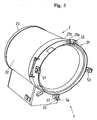
- FIG. 5 shows a headlamp 1, the light-generating and light-shaping elements, in particular a lamp, a Lamp holder, a reflector and a lens system (each not shown) arranged in a housing 2 are.
- the housing 2 consists of a front part 21, a Middle part 22 and a rear part 23.
- the front part 21st and the rear part 23 is preferably an aluminum casting, while the middle part 22 is preferably an aluminum extruded profile is.
- a bracket connected to the housing 2 is about the bracket of the headlight example put on a tripod.
- the front side 21 of the housing 1 consists of an annular Front ring 21a and a fixed lens frame 21b, in which the lenses of the headlamp used are. At the front ring 21a are evenly spaced four opposite the front part 21 projecting retaining claws 51, 52, 53, 54 arranged. The lateral retaining claws 51, 53 and the lower retaining claw 54 are fixed to the front ring 21a attached.
- the upper retaining claw 52 is with a Opening mechanism provided and can from the illustrated Tilted upwards.
- Each retaining claw 51, 52, 53, 54 has two grooves 61, 62, which serve to accommodate additional equipment. there can in a retaining claw 51, 52, 53, 54 instead of two grooves also only one receiving groove or three and more grooves are formed.
- retaining claws 51, 52, 52, 53, 54 instead of in a front ring 21a also directly at the Lens mount 21b may be formed, or at an in the lens mount used, superior or patch Part.
- the holding claws 51, 52, 53, 54 serve the inclusion of additional equipment such as diffusers, color foil filters and swing gate, in the retaining claws or the Receiving grooves 61, 62 of the retaining claws are mounted.
- the Accessories are included because of the heat development, the one Headlight causes, usually in metal frames taken, which then in the grooves 61, 62 of the retaining claws be used.
- the metal frames used for the accessory also show like the holding claws on a certain game. Especially The game of metal frames is sometimes very spectacular. This leads to the accessories or the metal frame of the Accessories for a movable headlight insert, for example in reports or when shooting in the car or other moving recordings, rattling noises in caused the retaining claws. Such a rattling sound is especially in a simultaneous sound recording however undesirable.
- From DE 196 12 048 A1 discloses a lamp housing with a releasable luminaire cover known in two opposite, held parallel grooves. In at least one of the grooves is a resilient element introduced to the lamp cover is resiliently applied.
- US 5 091 835 A describes a headlight in which a spring clip on a front lens support ring is provided, the recesses for receiving a lens or the like.
- the present invention is based on the object to provide a headlight that is safe prevents that arranged in retaining claws of the headlamp Additional equipment such as diffusers, color foil filters and Swing gates with a movable use of the headlamp Cause rattling noises.
- the retaining claws each having an elastic element or form, on which an additional device held by the retaining claws is applied.
- the elastic Element one consisting of an elastic material Pen or one made of an elastic material Hose segment, with respect to the headlight inserted in the axial direction in a bore of the retaining claw is.
- the elastic element has an elasticity on, which is greater than the elasticity of the associated retaining claw.
- the elastic element is dimensioned in such a way that there are tolerances of the accessories and the retaining claws compensated.
- the retaining claws preferably each have at least one Recess for receiving additional devices, wherein the elastic element respectively in the recess of the retaining claws is arranged. This will be a secure attachment an accessory on the retaining jaws allows.
- the elastic element is in each case in the recess arranged a retaining claw that it radially to one in the
- the elastic element is preferably about a pin which is cylindrical.
- An elastic Pen has the advantage that he at least in Radial direction is relatively strong deformed and therefore even with strong tolerances between additional device and Holding claw a secure and rattle-free holding the attachment guaranteed.
- the elastic element instead of a solid pin is the elastic element alternatively a hollow pin or one of an elastic Material existing hose segment.
- the training of the elastic element or pin as a hose segment provides an easy to implement variant About the material and the thickness of the wall of the Hose segment can determine its elasticity.
- At the (at least one) recess of the retaining claw acts it is preferably a groove, the one from a elastic material existing pin or the elastic Hose segment is transversely inserted through the groove through this while projecting at least partially opposite the groove bottom, such that an auxiliary device inserted into the groove at its radial end not the groove bottom, but the elastic pin or the hose segment contacted.
- the bore for receiving the elastic element is in Area of the groove bottom preferably designed as a half-hole, so that part of the elastic element from the groove bottom projects. This will be a safe and solid Connection of the elastic element with the retaining claw provided. It can also be provided that the elastic element in addition with an adhesive on the Retaining claw is secured. Generally this is elastic Element preferably by gluing or by gluing in conjunction with a positive connection to the retaining claw attached.
- the elastic element axially in front of the retaining claw. This ensures a silencing in the axial direction opposite on the outside of the retaining claw elements, such as parts a wing gate.
- the axially projecting portion of the elastic Elements is preferably rounded, in particular crowned.
- the inserted into the retaining claws elastic element has prefers a very opposite to the material of the retaining claws high elasticity, allowing a rattling of the attachment is reliably prevented and these springy on the headlight is held.
- the elastic element is preferred an elastic and heat-resistant plastic material, in particular a rubber-elastic material, such as an elastomer or rubber.
- FIG. 1 shows a front part 210 of a lamp housing four retaining claws 510 according to the invention arranged thereon, 520, 530, 540.
- Each retaining claw has an elongated receiving groove 600 for receiving a suspended in the retaining claws Recording device on.
- a Metal frame of a receiving device in the grooves 600th used.
- the front part 210 is in the illustrated embodiment around a so-called lens gate, which is the Recording the lens system of the headlight is used.
- the retaining claws 510, 520, 530, 540 can, however, also on a another front part, in particular a surrounding the lens gate Essay or an intent set in front of the lens gate (Compare intent 21a of Figure 5) may be arranged. It can also be provided that the retaining claws not only one receiving groove 600, but several in the axial direction have receiving grooves arranged one behind the other (compare grooves 61, 62 of FIG. 5).
- the retaining claws 510, 520, 530, 540 are preferred as Casting, in particular designed as an aluminum casting and firmly bolted or riveted to the front part 210.
- the retaining claws are integral, in particular as a one-piece casting together with the front part 210 educated. It can also be provided that it is at the retaining claws to profiled sheet metal parts or a hard Plastic acts.
- the retaining claws 510, 520, 530, 540 have a relatively low elasticity to relatively even heavy additional equipment rigidly on the headlight to be able to hold.
- FIG. 1 and 2 have the upper and lower retaining claws 520, 540 a rearwardly extending temple hanger 300 for Attachment of a bracket, not shown.
- These Temple hanger 300 can basically also on others Be part of the housing formed.
- the upper retaining claw 520 corresponding to the retaining claw 52 of Figure 5 with an opening mechanism (not shown), with the retaining claw can be tilted upwards to an insertion or removal of an accessory in the To allow retaining claws 510, 520, 530, 540 in a simple manner.
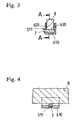
- the retaining claws 510, 520, 530, 540 each have a bore 511, in which one from a elastic material (for example an elastomer) existing cylindrical pin 7 is inserted.
- the Bore 511 extends transversely to the groove 600 and is, As shown in Figure 4, partially in the groove bottom 610th embedded.
- the bore 511 extends from the outer Leg 620 of the groove 600 in the direction of the inner leg 630 of the groove 600.
- the Bore 511 is designed as a half-hole, so that a part of the pin 7 protrudes from the groove bottom.
- An auxiliary device 8 inserted in the groove 600 (in FIG Figures 3 and 4 shown schematically) is accordingly the elastic pin 7, but not on the groove bottom 610.
- the elastic pin 7 has a diameter in this case on that, even taking into account manufacturing tolerances and due to heat differences resulting tolerances both the loading device 8 and the retaining claws the insertion device 8 resiliently against the elastic Element 7 presses and abuts against it. This will a firm, rattle-free fit of the accessory 8 in the receiving groove 600 is provided.
- the elastic pin 7 is preferably slightly in the opening 511 in the leg 620 of the groove pressed so that he a has a firm seat. Alternatively or additionally, the elastic Pin glued into the hole 511 to secure in the Retaining claw to sit.
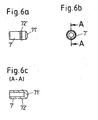
- Figs. 6a-c is another embodiment of a elastic element shown.
- the elastic element is formed as a hose segment 7 ', which as well as in 2-4 described in the groove 600 of the corresponding Holding claw is used.
- the hose segment 7 ' is for example a silicone rubber part with a hardness of 60 Shore.
- the hose segment 7 ' is at its out of the bore 511 (see Fig. 3) outstanding area 71 'closed and crowned. On the circumference formed locking hooks 72 ' prevent accidental falling out of the hole 511.
- the hose segment 7 ' is preferably through secured a suitable adhesive in the bore 511 (see Fig. 3).
- Fig. 7 shows a variant embodiment is shown, the except for the feature of the embodiment of FIG. 2 corresponds to that of the holding jaw 520, 540 or the groove 600 and the legs 620 in the axial direction protruding portion 71 of the pin 7 each formed crowned is. This advantageously allows one Noise damping also in the axial direction.
- the invention is not limited in their execution the embodiment shown above. It lies for example, also within the scope of the invention, as elastic element instead of an elastic pin or a hose segment to a groove-shaped insert use that is inserted into the groove of a retaining claw and radially and axially on an auxiliary device inserted in the groove is applied. It can also be provided that the Groove bottom is coated with a rubber layer.
- the retaining claw has or forms an elastic element the one held by the holding claw accessory a headlight is applied.
Landscapes
- Engineering & Computer Science (AREA)
- General Engineering & Computer Science (AREA)
- Lighting Device Outwards From Vehicle And Optical Signal (AREA)
- Non-Portable Lighting Devices Or Systems Thereof (AREA)
Abstract
Claims (12)
- Projeteur comportant un boítier, dans lequel sont disposés des éléments produisant et mettant en forme une lumière, dans lequel la partie avant (210) du boítier ou un élément d'application, d'insertion ou rapporté relié à la partie avant (210) du boítier comporte au moins deux griffes de retenue (510, 520, 530, 540) pour retenir des dispositifs supplémentaires tels que des diffuseurs, des filtres à feuilles colorées ou des portes d'avion, qui peuvent être montés au moyen des griffes de retenue sur la sortie pour la lumière du projecteur, les griffes de retenue (510, 520, 530, 540) comportant ou formant respectivement un élément élastique (7, 7'), sur lequel s'applique un dispositif supplémentaire retenu par la griffe de retenue,
caractérisé en ce que l'élément élastique est une tige (7) formée d'un matériau élastique ou un segment de tuyau (7') réalisé en un matériau élastique et est enfichée par rapport au projecteur dans une direction axiale, dans un perçage (511) de la griffe de retenue (510, 520, 530, 540). - Projecteur selon la revendication 1,
caractérisé en ce que les griffes de retenue (510, 520, 530, 540) possèdent respectivement au moins un évidement (600) servant à loger des dispositifs supplémentaires, et en ce que l'élément élastique (7, 7') est disposé dans l'évidement (600). - Projecteur selon la revendication 2,
caractérisé en ce que l'évidement est une rainure (600), et que l'élément élastique (7, 7') est enfiché dans cette rainure (600) transversalement par rapport à cette dernière et fait saillie au moins partiellement par rapport au fond (610) de la rainure. - Projecteur selon la revendication 3,
caractérisé en ce que le perçage (511) est agencé de manière à recevoir l'élément élastique (7, 7') dans la zone du fond (610) de la rainure en tant que demi-perçage. - Projecteur selon au moins l'une des revendications précédentes, caractérisé en ce que l'élément élastique (7, 7') fait saillie axialement par rapport à la griffe de retenue (510, 520, 530, 540).
- Projecteur selon la revendication 5,
caractérisé en ce que la partie axialement en saillie de l'élément élastique (7') est agencée avec une forme arrondie. - Projecteur selon au moins l'une des revendications précédentes, caractérisé en ce que l'élément élastique est fixé en supplément avec un adhésif à la griffe de retenue.
- Projecteur selon au moins l'une des revendications précédentes, caractérisé en ce que l'élément élastique (7, 7') est réalisé avec une forme cylindrique.
- Projecteur selon au moins l'une des revendications 2 à 8, caractérisé en ce que l'élément élastique est une pièce d'insertion, qui est insérée dans l'évidement.
- Projecteur selon au moins l'une des revendications précédentes, caractérisé en ce que l'élément élastique (7, 7') présente une élasticité par rapport à la griffe de retenue (510, 520, 530, 540).
- Projecteur selon au moins l'une des revendications précédentes, caractérisé en ce que quatre griffes de retenue (510, 520, 530, 540) sont disposées en étant réparties d'une manière uniforme sur la partie avant (21a, 210) du boítier et/ou d'un élément d'application, d'insertion ou rapporté à la partie avant du boítier.
- Projecteur selon la revendication 11,
caractérisé en ce que l'une des griffes (520) est fixée de manière à pouvoir basculer sur la partie avant (210) ou sur l'élément d'application, d'insertion ou rapporté.
Applications Claiming Priority (3)
| Application Number | Priority Date | Filing Date | Title |
|---|---|---|---|
| DE20107299U DE20107299U1 (de) | 2001-04-23 | 2001-04-23 | Scheinwerfer mit einem Gehäuse mit Halteklauen |
| DE20107299U | 2001-04-23 | ||
| PCT/DE2002/001529 WO2002086383A1 (fr) | 2001-04-23 | 2002-04-23 | Projecteur comportant un boitier pourvu de griffes de retenue |
Publications (2)
| Publication Number | Publication Date |
|---|---|
| EP1381809A1 EP1381809A1 (fr) | 2004-01-21 |
| EP1381809B1 true EP1381809B1 (fr) | 2005-10-12 |
Family
ID=7956301
Family Applications (1)
| Application Number | Title | Priority Date | Filing Date |
|---|---|---|---|
| EP02732408A Expired - Lifetime EP1381809B1 (fr) | 2001-04-23 | 2002-04-23 | Projecteur comportant un boitier pourvu de griffes de retenue |
Country Status (4)
| Country | Link |
|---|---|
| US (1) | US7040785B2 (fr) |
| EP (1) | EP1381809B1 (fr) |
| DE (2) | DE20107299U1 (fr) |
| WO (1) | WO2002086383A1 (fr) |
Families Citing this family (9)
| Publication number | Priority date | Publication date | Assignee | Title |
|---|---|---|---|---|
| DE20107299U1 (de) * | 2001-04-23 | 2001-08-09 | Arnold & Richter Cine Technik GmbH & Co Betriebs KG, 80799 München | Scheinwerfer mit einem Gehäuse mit Halteklauen |
| DE10151841B4 (de) * | 2001-10-24 | 2007-02-08 | Heraeus Noblelight Gmbh | Rechteckige Rahmenanordnung mit ein bis zwei scheibenförmigen Strahlungsfiltern und Bräunungsmodul |
| DE20207639U1 (de) * | 2002-05-14 | 2003-09-25 | Sonlux Licht- und Elektroinstallation GmbH & Co KG, 99706 Sondershausen | Optisches Element zur Beeinflussung der mit einer Leuchte bewirkten Beleuchtung sowie Leuchte und Gußform zur Herstellung eines optischen Elementes |
| DE20217193U1 (de) | 2002-11-07 | 2003-02-27 | Sachtler GmbH & Co. KG, 85716 Unterschleißheim | Halterung für einen Scheinwerferaufsatz |
| TWI260694B (en) * | 2005-08-19 | 2006-08-21 | Eric C H Chen | Structure for lighting element |
| WO2007128070A1 (fr) * | 2006-05-10 | 2007-11-15 | Spa Electrics Pty Ltd | Ensemble comprenant un dispositif de fixation |
| DE202006017131U1 (de) | 2006-10-12 | 2007-01-25 | Arnold & Richter Cine Technik Gmbh & Co. Betriebs Kg | Scheinwerfer zur Beleuchtung in Film-, Studio-, Event- oder Theaterumgebungen |
| ITGE20060020U1 (it) * | 2006-10-27 | 2008-04-28 | Tecnova Di Ciccarello Spitaler | Dispositivo per il supporto dei filtri per lampade solari |
| CN101793350B (zh) * | 2010-03-16 | 2012-06-27 | 海洋王照明科技股份有限公司 | 一种聚泛光的轻便移动灯 |
Family Cites Families (17)
| Publication number | Priority date | Publication date | Assignee | Title |
|---|---|---|---|---|
| US1303898A (en) * | 1919-05-20 | Shadb-holdeb | ||
| US1344695A (en) * | 1919-09-18 | 1920-06-29 | Thompson Alexander | Lens-holder for headlights |
| US1714289A (en) * | 1928-01-14 | 1929-05-21 | Indiana Lamp Corp | Lamp construction |
| US1761511A (en) * | 1929-03-02 | 1930-06-03 | Wolarsky Isidore | Lighting-fixture shade holder |
| US2291495A (en) * | 1941-02-21 | 1942-07-28 | Miller Co | Lighting fixture |
| US4187534A (en) * | 1976-11-08 | 1980-02-05 | Berkey-Colortran, Inc. | Universal lens mounting for selective spotlight beam spread |
| IT1178878B (it) * | 1984-03-13 | 1987-09-16 | Carello Ind Spa | Metodo per l assemblaggio di un proiettore di autoveicolo e proiettore ottenuto con tale metodo |
| DE3827594A1 (de) * | 1988-08-13 | 1990-02-15 | Hella Kg Hueck & Co | Verfahren zur herstellung und nach dem verfahren hergestelltes gestell fuer einen fahrzeugscheinwerfer nach dem projektionsverfahren |
| US5091835A (en) | 1991-02-25 | 1992-02-25 | Leonetti Company | High intensity lamp with improved air flow ventilation |
| DE4127128C2 (de) * | 1991-08-16 | 1994-07-14 | Huelsta Werke Huels Kg | Halterung von Vorsatzelementen an einem Beleuchtungskörper |
| DE4210439C2 (de) * | 1992-03-30 | 2003-06-12 | Hartmut S Engel | Vorsatzsystem für eine Strahlerleuchte |
| EP0620400B1 (fr) * | 1993-04-16 | 1996-03-20 | Siemens Aktiengesellschaft | Dispositif de fixation d'accessoires sur one armature lumineuse de plafond |
| DE4443682A1 (de) * | 1994-12-08 | 1996-06-13 | Bosch Gmbh Robert | Scheinwerfer für Fahrzeuge |
| DE19612048C2 (de) * | 1996-03-27 | 2001-03-22 | Gaz Grubenlampen Ind Und Gerae | Halterungsvorrichtung zur lösbaren Befestigung einer Leuchtenabdeckung |
| DE29621615U1 (de) * | 1996-12-12 | 1997-02-27 | Siemens AG, 80333 München | Halterung für eine Linse einer Beleuchtungsoptik |
| US6033095A (en) * | 1998-03-04 | 2000-03-07 | North American Lighting, Inc. | Vehicle headlamp housing with connector receiving breakaway portions |
| DE20107299U1 (de) * | 2001-04-23 | 2001-08-09 | Arnold & Richter Cine Technik GmbH & Co Betriebs KG, 80799 München | Scheinwerfer mit einem Gehäuse mit Halteklauen |
-
2001
- 2001-04-23 DE DE20107299U patent/DE20107299U1/de not_active Expired - Lifetime
-
2002
- 2002-04-23 WO PCT/DE2002/001529 patent/WO2002086383A1/fr not_active Ceased
- 2002-04-23 US US10/475,820 patent/US7040785B2/en not_active Expired - Fee Related
- 2002-04-23 EP EP02732408A patent/EP1381809B1/fr not_active Expired - Lifetime
- 2002-04-23 DE DE50204534T patent/DE50204534D1/de not_active Expired - Lifetime
Also Published As
| Publication number | Publication date |
|---|---|
| HK1057917A1 (en) | 2004-04-23 |
| DE20107299U1 (de) | 2001-08-09 |
| EP1381809A1 (fr) | 2004-01-21 |
| WO2002086383A1 (fr) | 2002-10-31 |
| US7040785B2 (en) | 2006-05-09 |
| DE50204534D1 (de) | 2006-02-23 |
| US20040170023A1 (en) | 2004-09-02 |
Similar Documents
| Publication | Publication Date | Title |
|---|---|---|
| DE10051805B4 (de) | WC-Sitzgelenk | |
| DE60012242T2 (de) | Mittel zum Verankern eines langgestreckten Gegenstandes | |
| EP1381809B1 (fr) | Projecteur comportant un boitier pourvu de griffes de retenue | |
| DE29611674U1 (de) | Mit einem aushängbaren Türscharnier baulich vereinigter Türfeststeller | |
| DE102015007784A1 (de) | Lenksäule mit elektro-mechanischer Fixiervorrichtung | |
| WO2003004901A1 (fr) | Palier caoutchoute, de preference palier de stabilisation et procede pour monter ledit palier | |
| DE202006000381U1 (de) | Haltevorrichtung für aufklappbare Autositze | |
| DE19707949C1 (de) | Befestigungsvorrichtung für ein Fahrzeugteil | |
| DE4228891A1 (de) | Einrichtung mit wenigstens zwei über eine Verstellschraube zueinander verstellbaren Bauteilen | |
| DE19546271B4 (de) | Scheinwerfer für Fahrzeuge mit einem verschwenkbaren Reflektor | |
| EP2006154B1 (fr) | Phare pour véhicules | |
| DE10115243A1 (de) | Fahrzeugsitz mit Lagervorrichtung | |
| EP2192003A1 (fr) | Dispositif d'éclairage pour un véhicule automobile | |
| DE19507586A1 (de) | Scheinwerfer für Fahrzeuge | |
| DE10337613B4 (de) | Puffervorrichtung für zwei relativ zueinander bewegbare Bauteile, wobei ein Bauteil eine Heckklappe und das andere Bauteil ein feststehendes Karosserieteil eines Kraftfahrzeugs ist | |
| DE3533118C2 (de) | Schraubanordnung für Einstelleinrichtungen von Kraftfahrzeug-Scheinwerfern | |
| DE102011000360A1 (de) | Beleuchtungsvorrichtung für Fahrzeuge und Befestigungsverfahren für die Beleuchtungsvorrichtung | |
| EP3574813B1 (fr) | Charnière pour un ensemble d'un siège de toilettes | |
| DE102021116803A1 (de) | Halter, Baukasten und Verfahren zum Montieren eines Halters | |
| DE202007007032U1 (de) | Befestigungsanordnung zur Befestigung einer Antriebseinheit eines Seil-Fensterhebers für Kraftfahrzeuge an einem plattenförmigen Träger sowie Kraftfahrzeugtür mit selbiger | |
| DE102015001605B3 (de) | Kraftfahrzeug | |
| DE69800004T2 (de) | Befestigungsvorrichtung für einen Aussenrückblickspiegel auf einem Kraftfahrzeug | |
| EP1747941A2 (fr) | Support de capteur pour fixer un capteur sur une partie de véhicule automobile | |
| DE2006383C3 (de) | Einstellvorrichtung für den Leuchteneinsatz von Scheinwerfern | |
| DE69711318T2 (de) | Vorrichtung zur schnellen Befestigung und Demontierung von Platten |
Legal Events
| Date | Code | Title | Description |
|---|---|---|---|
| PUAI | Public reference made under article 153(3) epc to a published international application that has entered the european phase |
Free format text: ORIGINAL CODE: 0009012 |
|
| 17P | Request for examination filed |
Effective date: 20031024 |
|
| AK | Designated contracting states |
Kind code of ref document: A1 Designated state(s): AT BE CH CY DE DK ES FI FR GB GR IE IT LI LU MC NL PT SE TR |
|
| GRAP | Despatch of communication of intention to grant a patent |
Free format text: ORIGINAL CODE: EPIDOSNIGR1 |
|
| RBV | Designated contracting states (corrected) |
Designated state(s): DE FR GB IT |
|
| GRAS | Grant fee paid |
Free format text: ORIGINAL CODE: EPIDOSNIGR3 |
|
| GRAA | (expected) grant |
Free format text: ORIGINAL CODE: 0009210 |
|
| AK | Designated contracting states |
Kind code of ref document: B1 Designated state(s): DE FR GB IT |
|
| REG | Reference to a national code |
Ref country code: GB Ref legal event code: FG4D Free format text: NOT ENGLISH |
|
| GBT | Gb: translation of ep patent filed (gb section 77(6)(a)/1977) |
Effective date: 20051128 |
|
| REG | Reference to a national code |
Ref country code: HK Ref legal event code: GR Ref document number: 1057917 Country of ref document: HK |
|
| REF | Corresponds to: |
Ref document number: 50204534 Country of ref document: DE Date of ref document: 20060223 Kind code of ref document: P |
|
| ET | Fr: translation filed | ||
| PLBE | No opposition filed within time limit |
Free format text: ORIGINAL CODE: 0009261 |
|
| STAA | Information on the status of an ep patent application or granted ep patent |
Free format text: STATUS: NO OPPOSITION FILED WITHIN TIME LIMIT |
|
| 26N | No opposition filed |
Effective date: 20060713 |
|
| PGFP | Annual fee paid to national office [announced via postgrant information from national office to epo] |
Ref country code: FR Payment date: 20110427 Year of fee payment: 10 Ref country code: DE Payment date: 20110318 Year of fee payment: 10 |
|
| PGFP | Annual fee paid to national office [announced via postgrant information from national office to epo] |
Ref country code: GB Payment date: 20110419 Year of fee payment: 10 |
|
| PGFP | Annual fee paid to national office [announced via postgrant information from national office to epo] |
Ref country code: IT Payment date: 20110422 Year of fee payment: 10 |
|
| GBPC | Gb: european patent ceased through non-payment of renewal fee |
Effective date: 20120423 |
|
| REG | Reference to a national code |
Ref country code: FR Ref legal event code: ST Effective date: 20121228 |
|
| PG25 | Lapsed in a contracting state [announced via postgrant information from national office to epo] |
Ref country code: GB Free format text: LAPSE BECAUSE OF NON-PAYMENT OF DUE FEES Effective date: 20120423 |
|
| REG | Reference to a national code |
Ref country code: DE Ref legal event code: R119 Ref document number: 50204534 Country of ref document: DE Effective date: 20121101 |
|
| PG25 | Lapsed in a contracting state [announced via postgrant information from national office to epo] |
Ref country code: FR Free format text: LAPSE BECAUSE OF NON-PAYMENT OF DUE FEES Effective date: 20120430 Ref country code: IT Free format text: LAPSE BECAUSE OF NON-PAYMENT OF DUE FEES Effective date: 20120423 |
|
| PG25 | Lapsed in a contracting state [announced via postgrant information from national office to epo] |
Ref country code: DE Free format text: LAPSE BECAUSE OF NON-PAYMENT OF DUE FEES Effective date: 20121101 |