EP1382468A2 - Aufhängungssystem - Google Patents
Aufhängungssystem Download PDFInfo
- Publication number
- EP1382468A2 EP1382468A2 EP03254524A EP03254524A EP1382468A2 EP 1382468 A2 EP1382468 A2 EP 1382468A2 EP 03254524 A EP03254524 A EP 03254524A EP 03254524 A EP03254524 A EP 03254524A EP 1382468 A2 EP1382468 A2 EP 1382468A2
- Authority
- EP
- European Patent Office
- Prior art keywords
- damping device
- magnetic
- suspension system
- vehicle suspension
- portions
- Prior art date
- Legal status (The legal status is an assumption and is not a legal conclusion. Google has not performed a legal analysis and makes no representation as to the accuracy of the status listed.)
- Granted
Links
- 239000000725 suspension Substances 0.000 title claims abstract description 58
- 238000013016 damping Methods 0.000 claims abstract description 61
- 230000035939 shock Effects 0.000 claims abstract description 9
- 239000006096 absorbing agent Substances 0.000 claims abstract description 8
- 230000003044 adaptive effect Effects 0.000 description 3
- 208000031872 Body Remains Diseases 0.000 description 1
- 238000007792 addition Methods 0.000 description 1
- 239000000853 adhesive Substances 0.000 description 1
- 230000001070 adhesive effect Effects 0.000 description 1
- 230000004075 alteration Effects 0.000 description 1
- 238000006243 chemical reaction Methods 0.000 description 1
- 238000006073 displacement reaction Methods 0.000 description 1
- 238000009434 installation Methods 0.000 description 1
- 238000005461 lubrication Methods 0.000 description 1
- 239000000696 magnetic material Substances 0.000 description 1
- 238000004519 manufacturing process Methods 0.000 description 1
- 238000012986 modification Methods 0.000 description 1
- 230000004048 modification Effects 0.000 description 1
- 239000002245 particle Substances 0.000 description 1
- 239000011435 rock Substances 0.000 description 1
- 238000007789 sealing Methods 0.000 description 1
Images
Classifications
-
- B—PERFORMING OPERATIONS; TRANSPORTING
- B60—VEHICLES IN GENERAL
- B60G—VEHICLE SUSPENSION ARRANGEMENTS
- B60G13/00—Resilient suspensions characterised by arrangement, location or type of vibration dampers
-
- F—MECHANICAL ENGINEERING; LIGHTING; HEATING; WEAPONS; BLASTING
- F16—ENGINEERING ELEMENTS AND UNITS; GENERAL MEASURES FOR PRODUCING AND MAINTAINING EFFECTIVE FUNCTIONING OF MACHINES OR INSTALLATIONS; THERMAL INSULATION IN GENERAL
- F16F—SPRINGS; SHOCK-ABSORBERS; MEANS FOR DAMPING VIBRATION
- F16F13/00—Units comprising springs of the non-fluid type as well as vibration-dampers, shock-absorbers, or fluid springs
-
- F—MECHANICAL ENGINEERING; LIGHTING; HEATING; WEAPONS; BLASTING
- F16—ENGINEERING ELEMENTS AND UNITS; GENERAL MEASURES FOR PRODUCING AND MAINTAINING EFFECTIVE FUNCTIONING OF MACHINES OR INSTALLATIONS; THERMAL INSULATION IN GENERAL
- F16F—SPRINGS; SHOCK-ABSORBERS; MEANS FOR DAMPING VIBRATION
- F16F6/00—Magnetic springs; Fluid magnetic springs, i.e. magnetic spring combined with a fluid
- F16F6/005—Magnetic springs; Fluid magnetic springs, i.e. magnetic spring combined with a fluid using permanent magnets only
Definitions
- the invention relates to suspension systems in general, and more particularly, to suspension systems for motor vehicles.
- Motor vehicle suspension systems are designed to absorb vibrational forces using a resilient member, such as a coil spring, and then dissipate those forces using a damping device, such as a shock absorber.
- a resilient member such as a coil spring
- the coil spring, or other resilient member also biases the vehicle tires to maintain firm contact with the road.
- a typical type of vehicle suspension system includes an assembly in which a shock absorber is coaxially mounted within a coil spring, such that the coil spring and the shock absorber act in parallel against the reaction forces of the vehicle tires against the road.
- the coil spring may be either a cylindrical coil spring, so as to provide an essentially constant compliance, or barrel shaped, so as to provide a compliance that varies with the displacement of the spring.
- one spring/coil assembly is coupled to each wheel.
- the design of the suspension system is a compromise between passenger comfort and vehicle handling concerns, as well as overall vehicle design constraints.
- the use of softer, more compliant springs adds to passenger comfort, but compliant springs are typically longer in length, which may raise the vehicle body height. Therefore, in some designs, auxiliary air or hydropneumatic springs are used in addition to a relatively compliant primary coil spring.
- the use of the auxiliary air or hydropneumatic spring allows the suspension system to be designed such that the vehicle body remains relatively close to the ground, despite the longer length of the more compliant spring.
- the use of an auxiliary spring in addition to the primary coil spring and a shock absorber, makes the suspension system more complex and more costly. Additionally, a more compliant spring may be more susceptible to damage under harsh driving conditions.
- adaptive suspension systems are sometimes installed in racing vehicles and high-end mass-market motor vehicles, such as luxury sedans.
- These adaptive motor vehicle suspension systems may include means to adaptively control the damping level and the resiliency of the suspension system by using a hydraulic or electromechanical actuator to replace the typical coil spring and shock absorber.
- Adaptive systems while allowing more control over the vehicle, are typically more expensive.
- U.S. Patent No. 3,770,290 to Bottalico discloses an alternative suspension system more suitable for lower-end mass-market motor vehicles.
- a set of permanent magnets or electromagnets serves as the resilient member and/or the damping member.
- the magnets of this suspension system are mounted in housings that are spaced vertically from one another and are maintained in coaxial relationship by a central guide or post. Like magnetic poles of the two magnets are positioned opposite each other such that they create magnetic forces of repulsion.
- the reference does not disclose how such a magnetic suspension system might be combined with other conventional suspension components, such as shocks and struts.
- the present invention provides a vehicle suspension system.
- the vehicle suspension system includes a damping device and first and second magnetic structures.
- the damping device has first and second opposite portions moveable in opposite directions toward and away from one another.
- the first portion of the damping device is adapted to be coupled to a motor vehicle frame and the second portion of the damping device is adapted to be coupled to a motor vehicle wheel mount structure such that the damping device is adapted to dampen movement of the first and second portions toward or away from one another.
- the first and second magnetic structures of the vehicle suspension system are connected to the first portion and second portion, respectively.
- the arrangement of like magnetic poles of the two magnetic structures creates a resilient magnetic bias sufficient to repel the first and second opposite portions during a relative movement of the portions toward one another.
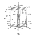
- FIGURE 1 An embodiment of a suspension system with magnetic resiliency is illustrated in the schematic sectional view of FIGURE 1.
- the suspension system generally indicated at reference numeral 10, includes a damping device 12, first and second magnetic structures 14, 16 and a sleeve 32.
- certain directional references e.g., "vertical,” “horizontal,” “top,” “bottom,” “upper,” “lower” are made with respect to the coordinate system of FIGURE 1, and may vary in an actual installation or use of suspension system 10.
- the damping device 12 is a conventional shock absorber, which may be of single-tube or twin-tube design. However, the damping device 12 may also be a strut or another conventionally known suspension damping member.
- the upper mount structure 20 on the first portion 18 of the damping device 12 may be adapted for connection to the upper control arm of the motor vehicle if the suspension system 10 is mounted between upper and lower control arms, or it may be adapted for connection to the vehicle frame if the suspension system 10 is mounted between the upper control arm and the vehicle frame.
- the lower mount structure 24 on the second portion 20 of the damping device 12 may be adapted for connection to the lower control arm of the motor vehicle if the suspension system 10 is mounted between upper and lower control arms, or it may be adapted for connection to the upper control arm if the suspension system 10 is mounted between the upper control arm and the vehicle frame.
- the motor vehicle is not shown in FIGURE 1.
- the damping device 12 is arranged to dissipate at least a portion of a force applied to the damping device 12 along a line of action L that extends between the first portion 18 and the second portion 22. More generally, the damping device 12 dampens movement of the first portion 18 and the second portion 22. For example, to dissipate or dampen a compressive force applied to the damping device 12 along the line of action L, the first and second portions 18, 22 of the damping device 12 would move toward one another.
- the two magnetic structures 14, 16 are arranged on the damping device 12 such that surfaces having like magnetic poles (e.g., surfaces 28 and 30 in FIGURE 1) are adjacent to and oppose one another, creating magnetic forces of repulsion, and thus, causing a resilient magnetic bias.
- the resilient magnetic bias acts to move the first and second portions 18, 22 of the damping device 12 away from one another.
- the resilient magnetic bias created by the first and second magnetic structures 14, 16 allows the suspension system 10 to absorb at least a portion of a force applied along line of action L and dampen movement of the suspension system.
- first and second magnetic structures 14, 16 illustrated in FIGURE 1 are annular in shape
- magnetic structures according to the invention need not be annular in shape.
- the two magnetic structures 14, 16 need not be contiguous over the outer circumference of the damping device 12.
- the two magnetic structures 14, 16 could be rectangular in shape, or given any other polygonal shape (e.g., rectangular, pentagonal, hexagonal) of sufficient size to receive the damping device 12 (e.g., using hole 26 as illustrated in FIGURE 1).
- the damping device 12 with attached first and second magnetic structures 14, 16 is received in an outer structure such as sleeve 32.
- the outer surfaces 36, 38 of the first and second magnetic structures 14, 16 are adapted to slidingly engage an interior bearing surface 34 of the sleeve 32 so as to provide a fluid-tight seal between the outer surfaces 36, 38 of the magnetic structures 14, 16 and the interior bearing surface 34 of the sleeve 32 (i.e., as in a piston-cylinder relationship).
- the bearing surfaces 34, 36, 38 may be provided with appropriate lubrication to prevent wear, or additional sealing structure (e.g., gaskets or O-rings) to facilitate the seal.
- the sleeve 32 also isolates the first and second magnetic structures 14, 16 and damper 12 and protects them from the road conditions to which the vehicle is exposed. In particular, the sleeve 32 may prevent the components from being damaged by small rocks, stones or other road particles that might be propelled into the suspension during driving.
- the sleeve 32 includes rubber boots 42 to assist in mounting the suspension system 10 to a motor vehicle and to absorb minor vibrations. Depending on the mounting of suspension system 10, rubber boots 42 may also be provided at the upper end to absorb minor vibrations.
- the sleeve 32 may not slidingly engage the two magnetic structures 14, 16, and instead, may merely contain the damping device 12 and magnetic structures 14, 16 and protect those components, as described above.
- the sleeve 32 and damping device 12 may be made of any non-magnetic material.
Landscapes
- Engineering & Computer Science (AREA)
- General Engineering & Computer Science (AREA)
- Mechanical Engineering (AREA)
- Vehicle Body Suspensions (AREA)
- Vibration Prevention Devices (AREA)
Applications Claiming Priority (2)
| Application Number | Priority Date | Filing Date | Title |
|---|---|---|---|
| US39663402P | 2002-07-19 | 2002-07-19 | |
| US396634P | 2002-07-19 |
Publications (3)
| Publication Number | Publication Date |
|---|---|
| EP1382468A2 true EP1382468A2 (de) | 2004-01-21 |
| EP1382468A3 EP1382468A3 (de) | 2004-02-04 |
| EP1382468B1 EP1382468B1 (de) | 2006-03-01 |
Family
ID=29780539
Family Applications (1)
| Application Number | Title | Priority Date | Filing Date |
|---|---|---|---|
| EP03254524A Expired - Lifetime EP1382468B1 (de) | 2002-07-19 | 2003-07-18 | Aufhängungssystem |
Country Status (6)
| Country | Link |
|---|---|
| US (1) | US20040012168A1 (de) |
| EP (1) | EP1382468B1 (de) |
| AT (1) | ATE318724T1 (de) |
| CA (1) | CA2435436A1 (de) |
| DE (1) | DE60303744T2 (de) |
| MX (1) | MXPA03006474A (de) |
Cited By (1)
| Publication number | Priority date | Publication date | Assignee | Title |
|---|---|---|---|---|
| US20100236872A1 (en) * | 2007-11-30 | 2010-09-23 | Otis Elevator Company | Passive magnetic elevator car steadier |
Families Citing this family (9)
| Publication number | Priority date | Publication date | Assignee | Title |
|---|---|---|---|---|
| DE102009018467A1 (de) * | 2009-04-22 | 2010-12-09 | Audi Ag | Modell- oder Spielauto |
| FI9958U1 (fi) * | 2012-09-14 | 2013-01-22 | Joakim Janson | Radio-ohjattavan auton etuakseliston kallistuksenvaimennus ja jousitus |
| MX2016007516A (es) * | 2013-12-20 | 2016-09-13 | Kimberly Clark Co | Compuestos termoadheridos por alargamiento basados en filamentos elasticos hidroenredados y metodos para fabricarlos. |
| US9556927B2 (en) * | 2014-03-17 | 2017-01-31 | Kyle Smith | Magnetic vibration isolation mount and method |
| US10208824B2 (en) * | 2015-06-03 | 2019-02-19 | Zachary Stein | Suspension assembly |
| WO2017068601A1 (en) * | 2015-10-20 | 2017-04-27 | Goduguchinta Vijaykumar Vaideeshwar | Magnetic suspension system for automobiles |
| CN106198523A (zh) * | 2016-07-06 | 2016-12-07 | 哈尔滨贝贝凯尔科技发展有限公司 | 微量元素检测试纸及其制备方法 |
| AR112542A1 (es) * | 2018-09-20 | 2019-11-06 | Luis Alberto Agra | Estabilizador magnético de suspensión inercial |
| CN113085466B (zh) * | 2021-05-08 | 2022-05-27 | 淄博职业学院 | 一种车辆磁悬减震系统 |
Citations (1)
| Publication number | Priority date | Publication date | Assignee | Title |
|---|---|---|---|---|
| US3770290A (en) | 1972-01-24 | 1973-11-06 | F Bottalico | Vehicle shock absorber |
Family Cites Families (21)
| Publication number | Priority date | Publication date | Assignee | Title |
|---|---|---|---|---|
| NL6712499A (de) * | 1967-09-13 | 1969-03-17 | ||
| US3939778A (en) * | 1972-05-08 | 1976-02-24 | Rohr Industries, Inc. | Railway truck magnetic suspension method |
| US3899979A (en) * | 1973-02-22 | 1975-08-19 | Buryan Associates | Magnetic suspension systems for vehicles |
| US3941402A (en) * | 1975-03-03 | 1976-03-02 | Yankowski Anthony P | Electromagnetic shock absorber |
| DE2554686A1 (de) * | 1975-12-05 | 1977-06-08 | Maschf Augsburg Nuernberg Ag | Vorrichtung zur abfederung einer achse |
| JPS5918182Y2 (ja) * | 1979-02-02 | 1984-05-26 | 「国」華工業株式会社 | 磁石の反発力を利用した磁気スプリング |
| JPS57169212A (en) * | 1981-04-13 | 1982-10-18 | Kokka Kogyo Kk | Vibration suppressing device |
| DE3410473C2 (de) * | 1983-04-11 | 1986-02-06 | Deutsche Forschungs- und Versuchsanstalt für Luft- und Raumfahrt e.V., 5000 Köln | Federungssystem für ein Kraftfahrzeug |
| JPS61215826A (ja) * | 1985-03-19 | 1986-09-25 | Sanai Kogyo Kk | 防振テ−ブル水平保持装置 |
| DE3347635A1 (de) * | 1985-04-25 | 1985-07-18 | Special'noe konstruktorskoe bjuro "Transprogress", Moskau/Moskva | Magnetisches gehaenge von transportmitteln |
| US4924778A (en) * | 1988-03-30 | 1990-05-15 | Kabushiki Kaisha Toshiba | Attraction type magnetic levitating apparatus |
| DE3935909A1 (de) * | 1989-11-01 | 1991-05-02 | Vnii Ochrany Truda I Techniki | Aufhaengung des sitzes von fahrzeugen |
| US5293969A (en) * | 1991-02-14 | 1994-03-15 | Atsugi Unisia Corporation | Electromagnetic suspension device |
| US5120030A (en) * | 1991-05-28 | 1992-06-09 | General Motors Corporation | Magnet assisted liftgate strut |
| US5431109A (en) * | 1993-04-14 | 1995-07-11 | Berdut; Elberto | Levitation and linear propulsion system using ceramic permanent magnets and interleaved malleable steel |
| US5452663A (en) * | 1993-04-14 | 1995-09-26 | Berdut; Elberto | Levitation and propulsion system using permanent magnets and interleaved iron or steel |
| US5440997A (en) * | 1993-09-27 | 1995-08-15 | Crowley; Walter A. | Magnetic suspension transportation system and method |
| US5652472A (en) * | 1995-12-19 | 1997-07-29 | Tozoni; Oleg V. | Magnetodynamic levitation and stabilizing selfregulating system |
| DE69729615T2 (de) * | 1996-04-08 | 2005-06-23 | Delta Tooling Co. Ltd. | Magnetische feder mit dämpfungseigenschaften und mit dieser befasstem schwingungsmechanismus |
| DE19840244A1 (de) * | 1998-09-03 | 2000-03-30 | Burgmann Dichtungswerk Feodor | Stoß- und Schwingungsdämpfer, insbesondere zur Aufhängung von Abgasanlagen von Kraftfahrzeugen |
| JP3115864B2 (ja) * | 1998-10-21 | 2000-12-11 | 株式会社デルタツーリング | 救急車用除振架台 |
-
2003
- 2003-07-09 US US10/614,991 patent/US20040012168A1/en not_active Abandoned
- 2003-07-16 CA CA002435436A patent/CA2435436A1/en not_active Abandoned
- 2003-07-18 DE DE60303744T patent/DE60303744T2/de not_active Expired - Lifetime
- 2003-07-18 MX MXPA03006474A patent/MXPA03006474A/es active IP Right Grant
- 2003-07-18 AT AT03254524T patent/ATE318724T1/de active
- 2003-07-18 EP EP03254524A patent/EP1382468B1/de not_active Expired - Lifetime
Patent Citations (1)
| Publication number | Priority date | Publication date | Assignee | Title |
|---|---|---|---|---|
| US3770290A (en) | 1972-01-24 | 1973-11-06 | F Bottalico | Vehicle shock absorber |
Cited By (2)
| Publication number | Priority date | Publication date | Assignee | Title |
|---|---|---|---|---|
| US20100236872A1 (en) * | 2007-11-30 | 2010-09-23 | Otis Elevator Company | Passive magnetic elevator car steadier |
| US8905197B2 (en) * | 2007-11-30 | 2014-12-09 | Otis Elevator Company | Passive magnetic elevator car steadier |
Also Published As
| Publication number | Publication date |
|---|---|
| MXPA03006474A (es) | 2004-10-15 |
| EP1382468A3 (de) | 2004-02-04 |
| DE60303744T2 (de) | 2006-11-30 |
| ATE318724T1 (de) | 2006-03-15 |
| US20040012168A1 (en) | 2004-01-22 |
| DE60303744D1 (de) | 2006-04-27 |
| CA2435436A1 (en) | 2004-01-19 |
| EP1382468B1 (de) | 2006-03-01 |
Similar Documents
| Publication | Publication Date | Title |
|---|---|---|
| US5263694A (en) | Upper mount assembly for a suspension damper | |
| CN102844206B (zh) | 用于具有倾斜功能的驾驶室悬架的双路径支架 | |
| US7287611B2 (en) | In-wheel motor system | |
| CN102085787B (zh) | 车轮悬挂 | |
| US20100327548A1 (en) | Structures, assemblies, and methods for controlling vehicle suspension | |
| JPH01172007A (ja) | 二重経路防振を有する空気ばね懸架装置 | |
| EP1382468B1 (de) | Aufhängungssystem | |
| US10843521B2 (en) | Method and apparatus for mitigating static loads in components connecting multiple structures | |
| US9200695B2 (en) | Spring and damper system, in particular for an assembly mount in a motor vehicle | |
| CN107627802B (zh) | 用于车辆的悬架系统缓冲装置及具有其的车辆 | |
| US10704634B2 (en) | Lower-side spring-receiving member | |
| US20130069293A1 (en) | Suspension device | |
| US20190257381A1 (en) | Damper assembly for a vehicle | |
| US11548342B2 (en) | Coilover shock absorber | |
| US11383571B2 (en) | Shock absorbers having internal jounce control | |
| US20090194920A1 (en) | Integrated Suspension Control Device | |
| US20040173984A1 (en) | Vehicle suspension apparatus | |
| US5186439A (en) | Friction compensating automotive suspension strut | |
| US5005855A (en) | Insulator device for strut type suspension system of automobile | |
| US11685212B2 (en) | Hydraulic jounce bumper with improved installation | |
| US20060049605A1 (en) | McPherson front corner module assembly with banana or s-shaped spring | |
| KR101880568B1 (ko) | 탈부착이 용이한 차량 시트용 완충장치 | |
| KR102750740B1 (ko) | 자동차 현가장치용 스프링 로어 패드 | |
| EP1375204B1 (de) | Kolbenstangendichtung für Stossdämpfer mit pneumatischer Niveauregulierung | |
| CN221075083U (zh) | 一种带限位弹簧垫的减震器 |
Legal Events
| Date | Code | Title | Description |
|---|---|---|---|
| PUAI | Public reference made under article 153(3) epc to a published international application that has entered the european phase |
Free format text: ORIGINAL CODE: 0009012 |
|
| PUAL | Search report despatched |
Free format text: ORIGINAL CODE: 0009013 |
|
| AK | Designated contracting states |
Kind code of ref document: A2 Designated state(s): AT BE BG CH CY CZ DE DK EE ES FI FR GB GR HU IE IT LI LU MC NL PT RO SE SI SK TR |
|
| AX | Request for extension of the european patent |
Extension state: AL LT LV MK |
|
| AK | Designated contracting states |
Kind code of ref document: A3 Designated state(s): AT BE BG CH CY CZ DE DK EE ES FI FR GB GR HU IE IT LI LU MC NL PT RO SE SI SK TR |
|
| AX | Request for extension of the european patent |
Extension state: AL LT LV MK |
|
| 17P | Request for examination filed |
Effective date: 20040521 |
|
| 17Q | First examination report despatched |
Effective date: 20040707 |
|
| AKX | Designation fees paid |
Designated state(s): AT BE BG CH CY CZ DE DK EE ES FI FR GB GR HU IE IT LI LU MC NL PT RO SE SI SK TR |
|
| GRAP | Despatch of communication of intention to grant a patent |
Free format text: ORIGINAL CODE: EPIDOSNIGR1 |
|
| GRAS | Grant fee paid |
Free format text: ORIGINAL CODE: EPIDOSNIGR3 |
|
| GRAA | (expected) grant |
Free format text: ORIGINAL CODE: 0009210 |
|
| AK | Designated contracting states |
Kind code of ref document: B1 Designated state(s): AT BE BG CH CY CZ DE DK EE ES FI FR GB GR HU IE IT LI LU MC NL PT RO SE SI SK TR |
|
| PG25 | Lapsed in a contracting state [announced via postgrant information from national office to epo] |
Ref country code: FI Free format text: LAPSE BECAUSE OF FAILURE TO SUBMIT A TRANSLATION OF THE DESCRIPTION OR TO PAY THE FEE WITHIN THE PRESCRIBED TIME-LIMIT Effective date: 20060301 Ref country code: SI Free format text: LAPSE BECAUSE OF FAILURE TO SUBMIT A TRANSLATION OF THE DESCRIPTION OR TO PAY THE FEE WITHIN THE PRESCRIBED TIME-LIMIT Effective date: 20060301 Ref country code: CH Free format text: LAPSE BECAUSE OF FAILURE TO SUBMIT A TRANSLATION OF THE DESCRIPTION OR TO PAY THE FEE WITHIN THE PRESCRIBED TIME-LIMIT Effective date: 20060301 Ref country code: SK Free format text: LAPSE BECAUSE OF FAILURE TO SUBMIT A TRANSLATION OF THE DESCRIPTION OR TO PAY THE FEE WITHIN THE PRESCRIBED TIME-LIMIT Effective date: 20060301 Ref country code: RO Free format text: LAPSE BECAUSE OF FAILURE TO SUBMIT A TRANSLATION OF THE DESCRIPTION OR TO PAY THE FEE WITHIN THE PRESCRIBED TIME-LIMIT Effective date: 20060301 Ref country code: LI Free format text: LAPSE BECAUSE OF FAILURE TO SUBMIT A TRANSLATION OF THE DESCRIPTION OR TO PAY THE FEE WITHIN THE PRESCRIBED TIME-LIMIT Effective date: 20060301 |
|
| REG | Reference to a national code |
Ref country code: GB Ref legal event code: FG4D |
|
| REG | Reference to a national code |
Ref country code: CH Ref legal event code: EP |
|
| REG | Reference to a national code |
Ref country code: IE Ref legal event code: FG4D |
|
| REF | Corresponds to: |
Ref document number: 60303744 Country of ref document: DE Date of ref document: 20060427 Kind code of ref document: P |
|
| PG25 | Lapsed in a contracting state [announced via postgrant information from national office to epo] |
Ref country code: DK Free format text: LAPSE BECAUSE OF FAILURE TO SUBMIT A TRANSLATION OF THE DESCRIPTION OR TO PAY THE FEE WITHIN THE PRESCRIBED TIME-LIMIT Effective date: 20060601 Ref country code: BG Free format text: LAPSE BECAUSE OF FAILURE TO SUBMIT A TRANSLATION OF THE DESCRIPTION OR TO PAY THE FEE WITHIN THE PRESCRIBED TIME-LIMIT Effective date: 20060601 Ref country code: SE Free format text: LAPSE BECAUSE OF FAILURE TO SUBMIT A TRANSLATION OF THE DESCRIPTION OR TO PAY THE FEE WITHIN THE PRESCRIBED TIME-LIMIT Effective date: 20060601 |
|
| PG25 | Lapsed in a contracting state [announced via postgrant information from national office to epo] |
Ref country code: ES Free format text: LAPSE BECAUSE OF FAILURE TO SUBMIT A TRANSLATION OF THE DESCRIPTION OR TO PAY THE FEE WITHIN THE PRESCRIBED TIME-LIMIT Effective date: 20060612 |
|
| PG25 | Lapsed in a contracting state [announced via postgrant information from national office to epo] |
Ref country code: IE Free format text: LAPSE BECAUSE OF NON-PAYMENT OF DUE FEES Effective date: 20060718 |
|
| PG25 | Lapsed in a contracting state [announced via postgrant information from national office to epo] |
Ref country code: MC Free format text: LAPSE BECAUSE OF NON-PAYMENT OF DUE FEES Effective date: 20060731 |
|
| PGFP | Annual fee paid to national office [announced via postgrant information from national office to epo] |
Ref country code: IT Payment date: 20060731 Year of fee payment: 4 |
|
| PG25 | Lapsed in a contracting state [announced via postgrant information from national office to epo] |
Ref country code: PT Free format text: LAPSE BECAUSE OF FAILURE TO SUBMIT A TRANSLATION OF THE DESCRIPTION OR TO PAY THE FEE WITHIN THE PRESCRIBED TIME-LIMIT Effective date: 20060801 |
|
| ET | Fr: translation filed | ||
| REG | Reference to a national code |
Ref country code: CH Ref legal event code: PL |
|
| PLBE | No opposition filed within time limit |
Free format text: ORIGINAL CODE: 0009261 |
|
| STAA | Information on the status of an ep patent application or granted ep patent |
Free format text: STATUS: NO OPPOSITION FILED WITHIN TIME LIMIT |
|
| 26N | No opposition filed |
Effective date: 20061204 |
|
| GBPC | Gb: european patent ceased through non-payment of renewal fee |
Effective date: 20070718 |
|
| PG25 | Lapsed in a contracting state [announced via postgrant information from national office to epo] |
Ref country code: GR Free format text: LAPSE BECAUSE OF FAILURE TO SUBMIT A TRANSLATION OF THE DESCRIPTION OR TO PAY THE FEE WITHIN THE PRESCRIBED TIME-LIMIT Effective date: 20060602 Ref country code: CZ Free format text: LAPSE BECAUSE OF FAILURE TO SUBMIT A TRANSLATION OF THE DESCRIPTION OR TO PAY THE FEE WITHIN THE PRESCRIBED TIME-LIMIT Effective date: 20060301 |
|
| PG25 | Lapsed in a contracting state [announced via postgrant information from national office to epo] |
Ref country code: GB Free format text: LAPSE BECAUSE OF NON-PAYMENT OF DUE FEES Effective date: 20070718 |
|
| PG25 | Lapsed in a contracting state [announced via postgrant information from national office to epo] |
Ref country code: EE Free format text: LAPSE BECAUSE OF FAILURE TO SUBMIT A TRANSLATION OF THE DESCRIPTION OR TO PAY THE FEE WITHIN THE PRESCRIBED TIME-LIMIT Effective date: 20060301 |
|
| PG25 | Lapsed in a contracting state [announced via postgrant information from national office to epo] |
Ref country code: TR Free format text: LAPSE BECAUSE OF FAILURE TO SUBMIT A TRANSLATION OF THE DESCRIPTION OR TO PAY THE FEE WITHIN THE PRESCRIBED TIME-LIMIT Effective date: 20060301 Ref country code: LU Free format text: LAPSE BECAUSE OF NON-PAYMENT OF DUE FEES Effective date: 20060718 Ref country code: HU Free format text: LAPSE BECAUSE OF FAILURE TO SUBMIT A TRANSLATION OF THE DESCRIPTION OR TO PAY THE FEE WITHIN THE PRESCRIBED TIME-LIMIT Effective date: 20060902 |
|
| PG25 | Lapsed in a contracting state [announced via postgrant information from national office to epo] |
Ref country code: CY Free format text: LAPSE BECAUSE OF FAILURE TO SUBMIT A TRANSLATION OF THE DESCRIPTION OR TO PAY THE FEE WITHIN THE PRESCRIBED TIME-LIMIT Effective date: 20060301 |
|
| PG25 | Lapsed in a contracting state [announced via postgrant information from national office to epo] |
Ref country code: IT Free format text: LAPSE BECAUSE OF NON-PAYMENT OF DUE FEES Effective date: 20070718 |
|
| PGFP | Annual fee paid to national office [announced via postgrant information from national office to epo] |
Ref country code: FR Payment date: 20110727 Year of fee payment: 9 |
|
| PGFP | Annual fee paid to national office [announced via postgrant information from national office to epo] |
Ref country code: DE Payment date: 20110713 Year of fee payment: 9 Ref country code: AT Payment date: 20110628 Year of fee payment: 9 |
|
| PGFP | Annual fee paid to national office [announced via postgrant information from national office to epo] |
Ref country code: BE Payment date: 20110712 Year of fee payment: 9 Ref country code: NL Payment date: 20110715 Year of fee payment: 9 |
|
| BERE | Be: lapsed |
Owner name: *MARTINREA INTERNATIONAL INC. Effective date: 20120731 |
|
| REG | Reference to a national code |
Ref country code: NL Ref legal event code: V1 Effective date: 20130201 |
|
| REG | Reference to a national code |
Ref country code: AT Ref legal event code: MM01 Ref document number: 318724 Country of ref document: AT Kind code of ref document: T Effective date: 20120718 |
|
| REG | Reference to a national code |
Ref country code: FR Ref legal event code: ST Effective date: 20130329 |
|
| PG25 | Lapsed in a contracting state [announced via postgrant information from national office to epo] |
Ref country code: DE Free format text: LAPSE BECAUSE OF NON-PAYMENT OF DUE FEES Effective date: 20130201 Ref country code: FR Free format text: LAPSE BECAUSE OF NON-PAYMENT OF DUE FEES Effective date: 20120731 Ref country code: NL Free format text: LAPSE BECAUSE OF NON-PAYMENT OF DUE FEES Effective date: 20130201 |
|
| PG25 | Lapsed in a contracting state [announced via postgrant information from national office to epo] |
Ref country code: BE Free format text: LAPSE BECAUSE OF NON-PAYMENT OF DUE FEES Effective date: 20120731 |
|
| PG25 | Lapsed in a contracting state [announced via postgrant information from national office to epo] |
Ref country code: AT Free format text: LAPSE BECAUSE OF NON-PAYMENT OF DUE FEES Effective date: 20120718 |
|
| REG | Reference to a national code |
Ref country code: DE Ref legal event code: R119 Ref document number: 60303744 Country of ref document: DE Effective date: 20130201 |