EP1382579A2 - Antriebseinrichtung zum Verschwenken eines Mündungsmechanismus zwischen einer Vor- und einer Fertigform einer Station eines Glasproduktionsmaschine - Google Patents
Antriebseinrichtung zum Verschwenken eines Mündungsmechanismus zwischen einer Vor- und einer Fertigform einer Station eines Glasproduktionsmaschine Download PDFInfo
- Publication number
- EP1382579A2 EP1382579A2 EP03010723A EP03010723A EP1382579A2 EP 1382579 A2 EP1382579 A2 EP 1382579A2 EP 03010723 A EP03010723 A EP 03010723A EP 03010723 A EP03010723 A EP 03010723A EP 1382579 A2 EP1382579 A2 EP 1382579A2
- Authority
- EP
- European Patent Office
- Prior art keywords
- drive device
- muzzle
- motor part
- muzzle mechanism
- drive
- Prior art date
- Legal status (The legal status is an assumption and is not a legal conclusion. Google has not performed a legal analysis and makes no representation as to the accuracy of the status listed.)
- Granted
Links
- 230000007246 mechanism Effects 0.000 title claims abstract description 48
- 238000007496 glass forming Methods 0.000 title 1
- 230000007306 turnover Effects 0.000 title 1
- 230000005540 biological transmission Effects 0.000 claims description 12
- 239000011521 glass Substances 0.000 claims description 11
- 238000006243 chemical reaction Methods 0.000 description 1
Images
Classifications
-
- C—CHEMISTRY; METALLURGY
- C03—GLASS; MINERAL OR SLAG WOOL
- C03B—MANUFACTURE, SHAPING, OR SUPPLEMENTARY PROCESSES
- C03B9/00—Blowing glass; Production of hollow glass articles
- C03B9/13—Blowing glass; Production of hollow glass articles in gob feeder machines
- C03B9/14—Blowing glass; Production of hollow glass articles in gob feeder machines in "blow" machines or in "blow-and-blow" machines
- C03B9/16—Blowing glass; Production of hollow glass articles in gob feeder machines in "blow" machines or in "blow-and-blow" machines in machines with turn-over moulds
- C03B9/165—Details of such machines, e.g. guide funnels, turn-over mechanisms
-
- F—MECHANICAL ENGINEERING; LIGHTING; HEATING; WEAPONS; BLASTING
- F16—ENGINEERING ELEMENTS AND UNITS; GENERAL MEASURES FOR PRODUCING AND MAINTAINING EFFECTIVE FUNCTIONING OF MACHINES OR INSTALLATIONS; THERMAL INSULATION IN GENERAL
- F16M—FRAMES, CASINGS OR BEDS OF ENGINES, MACHINES OR APPARATUS, NOT SPECIFIC TO ENGINES, MACHINES OR APPARATUS PROVIDED FOR ELSEWHERE; STANDS; SUPPORTS
- F16M11/00—Stands or trestles as supports for apparatus or articles placed thereon ; Stands for scientific apparatus such as gravitational force meters
- F16M11/02—Heads
- F16M11/04—Means for attachment of apparatus; Means allowing adjustment of the apparatus relatively to the stand
- F16M11/06—Means for attachment of apparatus; Means allowing adjustment of the apparatus relatively to the stand allowing pivoting
- F16M11/10—Means for attachment of apparatus; Means allowing adjustment of the apparatus relatively to the stand allowing pivoting around a horizontal axis
-
- F—MECHANICAL ENGINEERING; LIGHTING; HEATING; WEAPONS; BLASTING
- F16—ENGINEERING ELEMENTS AND UNITS; GENERAL MEASURES FOR PRODUCING AND MAINTAINING EFFECTIVE FUNCTIONING OF MACHINES OR INSTALLATIONS; THERMAL INSULATION IN GENERAL
- F16M—FRAMES, CASINGS OR BEDS OF ENGINES, MACHINES OR APPARATUS, NOT SPECIFIC TO ENGINES, MACHINES OR APPARATUS PROVIDED FOR ELSEWHERE; STANDS; SUPPORTS
- F16M11/00—Stands or trestles as supports for apparatus or articles placed thereon ; Stands for scientific apparatus such as gravitational force meters
- F16M11/02—Heads
- F16M11/18—Heads with mechanism for moving the apparatus relatively to the stand
Definitions
- the invention relates to a drive device for Swiveling a muzzle mechanism between a preliminary and a finished form of a station of a glass production machine with a motor part, by means of which the drive energy can be generated for pivoting the muzzle mechanism, and a power transmission member arranged on the muzzle mechanism and by means of which the drive energy generated by the motor part convertible into the pivoting movement of the muzzle mechanism is.
- the invention has for its object a drive device for pivoting a muzzle mechanism between a pre and a finished form of a station of a glass production machine available with the help of an engine part by means of the pivotal movement of the muzzle mechanism is more controllable and controllable.
- the drive device is the output part on the engine part side designed as a drive gear, which meshes with one another with the muzzle mechanism side designed as a gear or ring Power transmission link is. In this way, the drive energy generated by the motor part can be transferred exactly to the muzzle mechanism.
- the motor part is expediently used as a servo geared motor educated.
- the drive device according to the invention can also muzzle mechanisms previously driven in a different way become, i.e. the drive device according to the invention can be adapted to existing muzzle mechanisms. It is practically universally applicable.
- a control unit of the motor part or the servo geared motor can be placed both externally and in a machine control be integrated into the glass production machine.
- control unit of the motor part or the servo geared motor a PC with visualization software is advantageously assigned, so the pivotal movement of the muzzle mechanism accordingly exactly in the control unit and can be visualized using the PC.
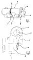
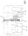
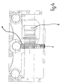
- a drive device shown in more detail with reference to FIGS. 1 to 4 1 for pivoting a muzzle mechanism 2 includes a servo geared motor 3.
- a servo geared motor 3 By means of the servo geared motor 3 becomes the driving energy for pivoting the muzzle mechanism 2 generated.
- the servo geared motor 3 has an output member attached to it Drive gear 4.
- the servo geared motor 3 is held on a mounting bracket 5, which in turn attached to a pre-form console 6 is.
- the arrangement of the servo geared motor 3 is selected so that that this is just below in the vertical direction the muzzle mechanism 2 sits.
- the servo gear motor side Drive gear 4 meshes with a firmly on the muzzle mechanism 2 seated gear or ring gear 7, so that the rotational movement generated by the servo geared motor 3 due to the direct meshing between the servo gear motor side Drive gear 4 and the muzzle mechanism side Gear or ring gear 7 directly in the Pivotal movement of the muzzle mechanism 2 is implemented.
- the muzzle mechanism 2 is that in FIGS. 1 to 4 shown embodiment by means of two journal bearings 8 or pivotable on side supports 9 of the preforming console 6 stored.
- a control unit is assigned to the servo geared motor 3, which are either designed as an external control unit or in a machine control of the glass machine can be integrated can.
- the control unit of the servo geared motor 3 can be a PC be assigned with visualization software.
- Control unit including cabling and PC with visualization software, the latter only being optionally provided can be, on previously differently driven muzzle mechanisms 2 can be installed.
Landscapes
- Engineering & Computer Science (AREA)
- General Engineering & Computer Science (AREA)
- Mechanical Engineering (AREA)
- Chemical & Material Sciences (AREA)
- Materials Engineering (AREA)
- Organic Chemistry (AREA)
- Manufacturing & Machinery (AREA)
- Transmission Devices (AREA)
- Re-Forming, After-Treatment, Cutting And Transporting Of Glass Products (AREA)
- Moulding By Coating Moulds (AREA)
- Processing And Handling Of Plastics And Other Materials For Molding In General (AREA)
- Blow-Moulding Or Thermoforming Of Plastics Or The Like (AREA)
- Glass Compositions (AREA)
Abstract
Description
- Figur 1
- eine perspektivische Ansicht einer Ausführungsform einer erfindungsgemäßen Antriebseinrichtung zum Verschwenken eines Mündungsmechanismus zwischen einer Vor- und einer Fertigform einer Station einer Glasproduktionsmaschine;
- Figur 2
- eine Seitenansicht der in Figur 1 gezeigten Ausführungsform der erfindungsgemäßen Antriebseinrichtung;
- Figur 3
- eine Vorderansicht der in Figur 1 gezeigten Ausführungform der erfindungsgemäßen Antriebseinrichtung; und
- Figur 4
- eine Draufsicht der in Figur 1 gezeigten Ausführungsform der erfindungsgemäßen Antriebseinrichtung.
Claims (8)
- Antriebseinrichtung zum Verschwenken eines Mündungsmechanismus (2) zwischen einer Vor- und einer Fertigform einer Station einer Glasproduktionsmaschine, mit einem Motorteil (3), mittels dem die Antriebsenergie zum Verschwenken des Mündungsmechanismus (2) erzeugbar ist, und einem Kraftübertragungsglied (7), das am Mündungsmechanismus (2) angeordnet und mittels dem die vom Motorteil (3) erzeugte Antriebsenergie in die Schwenkbewegung des Mündungsmechanismus (2) umwandelbar ist, dadurch gekennzeichnet, dass ein Ausgangsglied (4) des Motorteils (3) in unmittelbarem Eingriff mit dem Kraftübertragungsglied (7) des Mündungsmechanismus (2) ist.
- Antriebseinrichtung nach Anspruch 1, bei der das motorteilseitige Ausgangsglied als Antriebszahn (4) ausgebildet ist, das in Kämmeingriff mit dem als Zahnrad bzw. - kranz (7) ausgebildeten mündungsmechanismusseitigen Kraftübertragungsglied ist.
- Antriebseinrichtung nach Anspruch 1 oder 2, deren Motorteil als Servogetriebemotor (3) ausgebildet ist.
- Antriebseinrichtung nach einem der Ansprüche 1 bis 3, bei der das Motorteil (3) direkt unterhalb des Mündungsmechanismus (2) an einer Fertigformkonsole (6) der Glasproduktionsmaschine angeordnet ist.
- Antriebseinrichtung nach einem der Ansprüche 1 bis 4, bei der das Motorteil (3) mittels einer Aufnahmekonsole (5) an der Fertigformkonsole (6) der Glasproduktionsmaschine gehaltert ist.
- Antriebseinrichtung nach einem der Ansprüche 1 bis 5, bei der eine Steuereinheit des Motorteils (3) extern angeordnet ist.
- Antriebseinrichtung nach einem der Ansprüche 1 bis 5, bei der eine Steuereinheit des Motorteils (3) in eine Maschinensteuerung der Glasproduktionsmaschine integriert ist.
- Antriebseinrichtung nach Anspruch 6 oder 7, bei der der Steuereinheit des Motorteils (3) ein PC mit Visualisierungssoftware zugeordnet ist.
Applications Claiming Priority (2)
| Application Number | Priority Date | Filing Date | Title |
|---|---|---|---|
| DE10232241 | 2002-07-17 | ||
| DE10232241A DE10232241B4 (de) | 2002-07-17 | 2002-07-17 | Antriebseinrichtung zum Verschwenken eines Mündungsmechanismus zwischen einer Vor- und einer Fertigform einer Station einer Glasproduktionsmaschine |
Publications (4)
| Publication Number | Publication Date |
|---|---|
| EP1382579A2 true EP1382579A2 (de) | 2004-01-21 |
| EP1382579A3 EP1382579A3 (de) | 2006-07-26 |
| EP1382579B1 EP1382579B1 (de) | 2009-12-23 |
| EP1382579B8 EP1382579B8 (de) | 2010-03-10 |
Family
ID=29762008
Family Applications (1)
| Application Number | Title | Priority Date | Filing Date |
|---|---|---|---|
| EP03010723A Expired - Lifetime EP1382579B8 (de) | 2002-07-17 | 2003-05-14 | Antriebseinrichtung zum Verschwenken eines Mündungsmechanismus zwischen einer Vor- und einer Fertigform einer Station einer Glasproduktionsmaschine |
Country Status (3)
| Country | Link |
|---|---|
| EP (1) | EP1382579B8 (de) |
| AT (1) | ATE452860T1 (de) |
| DE (2) | DE10232241B4 (de) |
Citations (8)
| Publication number | Priority date | Publication date | Assignee | Title |
|---|---|---|---|---|
| US4548637A (en) | 1984-08-30 | 1985-10-22 | Owens-Illinois, Inc. | Servo-control of machine motions in manufacture of glass containers |
| EP0365718A1 (de) | 1987-10-02 | 1990-05-02 | Vhc Limited | Hydraulischer Umsetzmechanismus für Neckform |
| US4986844A (en) | 1988-05-27 | 1991-01-22 | Emhart Industries, Inc. | Glassware forming machine of the individual section type |
| EP0790218A2 (de) | 1996-02-15 | 1997-08-20 | Emhart Glass Machinery Investments Inc. | Übertragungsmechanismus |
| DE19851049A1 (de) | 1997-11-06 | 1999-05-12 | Emhart Glass Sa | IS-Maschine |
| EP1127852A2 (de) | 2000-02-22 | 2001-08-29 | BOTTERO S.p.A. | Umdrehmechnismus für eine Maschine zur Herstellung von Glaswaren |
| EP1151970A2 (de) | 2000-05-03 | 2001-11-07 | BOTTERO S.p.A. | Umdrehmechanismus für eine Maschine zur Herstellung von Hohlglasgegenstände |
| WO2002018283A1 (de) | 2000-08-26 | 2002-03-07 | Firma Hermann Heye | Invertmechanismus für eine glasformmaschine |
Family Cites Families (1)
| Publication number | Priority date | Publication date | Assignee | Title |
|---|---|---|---|---|
| CA1192406A (en) * | 1981-03-30 | 1985-08-27 | Eustace H. Mumford | Electronic control glass forming machine |
-
2002
- 2002-07-17 DE DE10232241A patent/DE10232241B4/de not_active Expired - Fee Related
-
2003
- 2003-05-14 DE DE50312254T patent/DE50312254D1/de not_active Expired - Lifetime
- 2003-05-14 EP EP03010723A patent/EP1382579B8/de not_active Expired - Lifetime
- 2003-05-14 AT AT03010723T patent/ATE452860T1/de not_active IP Right Cessation
Patent Citations (8)
| Publication number | Priority date | Publication date | Assignee | Title |
|---|---|---|---|---|
| US4548637A (en) | 1984-08-30 | 1985-10-22 | Owens-Illinois, Inc. | Servo-control of machine motions in manufacture of glass containers |
| EP0365718A1 (de) | 1987-10-02 | 1990-05-02 | Vhc Limited | Hydraulischer Umsetzmechanismus für Neckform |
| US4986844A (en) | 1988-05-27 | 1991-01-22 | Emhart Industries, Inc. | Glassware forming machine of the individual section type |
| EP0790218A2 (de) | 1996-02-15 | 1997-08-20 | Emhart Glass Machinery Investments Inc. | Übertragungsmechanismus |
| DE19851049A1 (de) | 1997-11-06 | 1999-05-12 | Emhart Glass Sa | IS-Maschine |
| EP1127852A2 (de) | 2000-02-22 | 2001-08-29 | BOTTERO S.p.A. | Umdrehmechnismus für eine Maschine zur Herstellung von Glaswaren |
| EP1151970A2 (de) | 2000-05-03 | 2001-11-07 | BOTTERO S.p.A. | Umdrehmechanismus für eine Maschine zur Herstellung von Hohlglasgegenstände |
| WO2002018283A1 (de) | 2000-08-26 | 2002-03-07 | Firma Hermann Heye | Invertmechanismus für eine glasformmaschine |
Also Published As
| Publication number | Publication date |
|---|---|
| ATE452860T1 (de) | 2010-01-15 |
| EP1382579B1 (de) | 2009-12-23 |
| EP1382579B8 (de) | 2010-03-10 |
| DE10232241A1 (de) | 2004-02-05 |
| EP1382579A3 (de) | 2006-07-26 |
| DE10232241B4 (de) | 2005-11-03 |
| DE50312254D1 (de) | 2010-02-04 |
Similar Documents
| Publication | Publication Date | Title |
|---|---|---|
| EP2271455B1 (de) | Bearbeitungskopf | |
| DE102008041190B4 (de) | Verfahren zur Positionierung von Stringern auf einer Flugzeughaut sowie eine Einrichtung zur Durchführung dieses Verfahrens | |
| DE3540001C2 (de) | ||
| DE19611661C2 (de) | Vorrichtung zum Formen von Draht, insbesondere Universal-Federwindemaschine | |
| DE102012004547A1 (de) | Vorrichtung zur Feinbearbeitung von optisch wirksamen Flächen an insbesondere Brillengläsern und flexible Fertigungszelle umfassend eine solche Vorrichtung | |
| DE112009004837B4 (de) | Schneidemaschine mit numerischer Steuerung | |
| DE112016005625T5 (de) | Vorrichtung zum Spritzgießen von Kunststoffmaterialien | |
| DE102020126189A1 (de) | Vorrichtung zur automatisierten Herstellung von Schraubverbindungen | |
| DE29916216U1 (de) | Vorrichtung zum Antrieb zweier Formhälftenhalter einer Glasformmaschine | |
| DE102012103957A1 (de) | Herstellung von Hohlkörpern aus einer Glasschmelze | |
| DE102012213421A1 (de) | Industrieroboter | |
| EP1382579B1 (de) | Antriebseinrichtung zum Verschwenken eines Mündungsmechanismus zwischen einer Vor- und einer Fertigform einer Station eines Glasproduktionsmaschine | |
| DE4223314A1 (de) | Einrichtung zum Schließen und Öffnen von Formen | |
| EP1093869A2 (de) | Vorrichtung zum Biegen und/oder Stanzen und/oder Stauchen von Draht-oder steifenartigen Blechteilen | |
| EP0979159B1 (de) | Erweiterungsaggregat für ein bearbeitungszentrum | |
| DE10249201B4 (de) | Verfahren und Vorrichtung zur Fixierung der Schweißposition | |
| DE19819277A1 (de) | Transfereinrichtung zum Transport von Werkstücken durch eine Stufenpresse, Transferpressenlinie oder dgl. Pressenanlage | |
| EP2490886B1 (de) | Arbeitsverfahren und einrichtung zum betreiben von pressen | |
| EP2473452A1 (de) | Vorformstation einer glasmaschine | |
| DE69904080T2 (de) | Vorrichtung zum umkippen von einem warmumformwerkzeug mit einer schraubenförmig bewegten nockenfolgeeinheit | |
| EP0855370B1 (de) | Antriebseinrichtung für einen Tropfenverteiler einer Glasmaschine | |
| DE9212648U1 (de) | Pegelmechanismus, Wendemechanismus und Greifermechanismus für eine IS-Glasverarbeitungsmaschine | |
| EP0603756B1 (de) | Verfahren und Anordnung zur spanabhebenden Herstellung einer torischen asphärischen konkaven Fläche an einem Kontaktlinsenrohling | |
| EP0896956A1 (de) | Pegelmechanismus für eine Vor- oder Fertigform einer Glasmaschine | |
| DE10122943A1 (de) | Blasform-Schließeinheit |
Legal Events
| Date | Code | Title | Description |
|---|---|---|---|
| PUAI | Public reference made under article 153(3) epc to a published international application that has entered the european phase |
Free format text: ORIGINAL CODE: 0009012 |
|
| AK | Designated contracting states |
Kind code of ref document: A2 Designated state(s): AT BE BG CH CY CZ DE DK EE ES FI FR GB GR HU IE IT LI LU MC NL PT RO SE SI SK TR |
|
| AX | Request for extension of the european patent |
Extension state: AL LT LV MK |
|
| PUAL | Search report despatched |
Free format text: ORIGINAL CODE: 0009013 |
|
| AK | Designated contracting states |
Kind code of ref document: A3 Designated state(s): AT BE BG CH CY CZ DE DK EE ES FI FR GB GR HU IE IT LI LU MC NL PT RO SE SI SK TR |
|
| AX | Request for extension of the european patent |
Extension state: AL LT LV MK |
|
| 17P | Request for examination filed |
Effective date: 20061227 |
|
| AKX | Designation fees paid |
Designated state(s): AT BE BG CH CY CZ DE DK EE ES FI FR GB GR HU IE IT LI LU MC NL PT RO SE SI SK TR |
|
| 17Q | First examination report despatched |
Effective date: 20070403 |
|
| GRAP | Despatch of communication of intention to grant a patent |
Free format text: ORIGINAL CODE: EPIDOSNIGR1 |
|
| GRAS | Grant fee paid |
Free format text: ORIGINAL CODE: EPIDOSNIGR3 |
|
| GRAA | (expected) grant |
Free format text: ORIGINAL CODE: 0009210 |
|
| AK | Designated contracting states |
Kind code of ref document: B1 Designated state(s): AT BE BG CH CY CZ DE DK EE ES FI FR GB GR HU IE IT LI LU MC NL PT RO SE SI SK TR |
|
| REG | Reference to a national code |
Ref country code: GB Ref legal event code: FG4D Free format text: NOT ENGLISH |
|
| REG | Reference to a national code |
Ref country code: CH Ref legal event code: EP |
|
| REG | Reference to a national code |
Ref country code: IE Ref legal event code: FG4D |
|
| REF | Corresponds to: |
Ref document number: 50312254 Country of ref document: DE Date of ref document: 20100204 Kind code of ref document: P |
|
| REG | Reference to a national code |
Ref country code: CH Ref legal event code: NV Representative=s name: E. BLUM & CO. AG PATENT- UND MARKENANWAELTE VSP |
|
| REG | Reference to a national code |
Ref country code: SE Ref legal event code: TRGR |
|
| REG | Reference to a national code |
Ref country code: NL Ref legal event code: VDEP Effective date: 20091223 |
|
| PG25 | Lapsed in a contracting state [announced via postgrant information from national office to epo] |
Ref country code: FI Free format text: LAPSE BECAUSE OF FAILURE TO SUBMIT A TRANSLATION OF THE DESCRIPTION OR TO PAY THE FEE WITHIN THE PRESCRIBED TIME-LIMIT Effective date: 20091223 |
|
| PG25 | Lapsed in a contracting state [announced via postgrant information from national office to epo] |
Ref country code: SI Free format text: LAPSE BECAUSE OF FAILURE TO SUBMIT A TRANSLATION OF THE DESCRIPTION OR TO PAY THE FEE WITHIN THE PRESCRIBED TIME-LIMIT Effective date: 20091223 |
|
| REG | Reference to a national code |
Ref country code: IE Ref legal event code: FD4D |
|
| PG25 | Lapsed in a contracting state [announced via postgrant information from national office to epo] |
Ref country code: RO Free format text: LAPSE BECAUSE OF FAILURE TO SUBMIT A TRANSLATION OF THE DESCRIPTION OR TO PAY THE FEE WITHIN THE PRESCRIBED TIME-LIMIT Effective date: 20091223 Ref country code: BG Free format text: LAPSE BECAUSE OF FAILURE TO SUBMIT A TRANSLATION OF THE DESCRIPTION OR TO PAY THE FEE WITHIN THE PRESCRIBED TIME-LIMIT Effective date: 20100323 Ref country code: ES Free format text: LAPSE BECAUSE OF FAILURE TO SUBMIT A TRANSLATION OF THE DESCRIPTION OR TO PAY THE FEE WITHIN THE PRESCRIBED TIME-LIMIT Effective date: 20100403 Ref country code: EE Free format text: LAPSE BECAUSE OF FAILURE TO SUBMIT A TRANSLATION OF THE DESCRIPTION OR TO PAY THE FEE WITHIN THE PRESCRIBED TIME-LIMIT Effective date: 20091223 Ref country code: NL Free format text: LAPSE BECAUSE OF FAILURE TO SUBMIT A TRANSLATION OF THE DESCRIPTION OR TO PAY THE FEE WITHIN THE PRESCRIBED TIME-LIMIT Effective date: 20091223 Ref country code: PT Free format text: LAPSE BECAUSE OF FAILURE TO SUBMIT A TRANSLATION OF THE DESCRIPTION OR TO PAY THE FEE WITHIN THE PRESCRIBED TIME-LIMIT Effective date: 20100423 |
|
| PG25 | Lapsed in a contracting state [announced via postgrant information from national office to epo] |
Ref country code: SK Free format text: LAPSE BECAUSE OF FAILURE TO SUBMIT A TRANSLATION OF THE DESCRIPTION OR TO PAY THE FEE WITHIN THE PRESCRIBED TIME-LIMIT Effective date: 20091223 |
|
| PG25 | Lapsed in a contracting state [announced via postgrant information from national office to epo] |
Ref country code: CY Free format text: LAPSE BECAUSE OF FAILURE TO SUBMIT A TRANSLATION OF THE DESCRIPTION OR TO PAY THE FEE WITHIN THE PRESCRIBED TIME-LIMIT Effective date: 20091223 Ref country code: IE Free format text: LAPSE BECAUSE OF FAILURE TO SUBMIT A TRANSLATION OF THE DESCRIPTION OR TO PAY THE FEE WITHIN THE PRESCRIBED TIME-LIMIT Effective date: 20091223 Ref country code: GR Free format text: LAPSE BECAUSE OF FAILURE TO SUBMIT A TRANSLATION OF THE DESCRIPTION OR TO PAY THE FEE WITHIN THE PRESCRIBED TIME-LIMIT Effective date: 20100324 |
|
| PLBE | No opposition filed within time limit |
Free format text: ORIGINAL CODE: 0009261 |
|
| STAA | Information on the status of an ep patent application or granted ep patent |
Free format text: STATUS: NO OPPOSITION FILED WITHIN TIME LIMIT |
|
| BERE | Be: lapsed |
Owner name: GPS GLASPRODUKTIONS-SERVICE G.M.B.H. Effective date: 20100531 |
|
| 26N | No opposition filed |
Effective date: 20100924 |
|
| PG25 | Lapsed in a contracting state [announced via postgrant information from national office to epo] |
Ref country code: MC Free format text: LAPSE BECAUSE OF NON-PAYMENT OF DUE FEES Effective date: 20100531 |
|
| GBPC | Gb: european patent ceased through non-payment of renewal fee |
Effective date: 20100514 |
|
| PG25 | Lapsed in a contracting state [announced via postgrant information from national office to epo] |
Ref country code: DK Free format text: LAPSE BECAUSE OF FAILURE TO SUBMIT A TRANSLATION OF THE DESCRIPTION OR TO PAY THE FEE WITHIN THE PRESCRIBED TIME-LIMIT Effective date: 20091223 |
|
| PG25 | Lapsed in a contracting state [announced via postgrant information from national office to epo] |
Ref country code: BE Free format text: LAPSE BECAUSE OF NON-PAYMENT OF DUE FEES Effective date: 20100531 |
|
| PG25 | Lapsed in a contracting state [announced via postgrant information from national office to epo] |
Ref country code: GB Free format text: LAPSE BECAUSE OF NON-PAYMENT OF DUE FEES Effective date: 20100514 |
|
| PG25 | Lapsed in a contracting state [announced via postgrant information from national office to epo] |
Ref country code: AT Free format text: LAPSE BECAUSE OF NON-PAYMENT OF DUE FEES Effective date: 20100514 |
|
| PGFP | Annual fee paid to national office [announced via postgrant information from national office to epo] |
Ref country code: FR Payment date: 20120608 Year of fee payment: 10 |
|
| PG25 | Lapsed in a contracting state [announced via postgrant information from national office to epo] |
Ref country code: HU Free format text: LAPSE BECAUSE OF FAILURE TO SUBMIT A TRANSLATION OF THE DESCRIPTION OR TO PAY THE FEE WITHIN THE PRESCRIBED TIME-LIMIT Effective date: 20100624 Ref country code: LU Free format text: LAPSE BECAUSE OF NON-PAYMENT OF DUE FEES Effective date: 20100514 |
|
| PG25 | Lapsed in a contracting state [announced via postgrant information from national office to epo] |
Ref country code: TR Free format text: LAPSE BECAUSE OF FAILURE TO SUBMIT A TRANSLATION OF THE DESCRIPTION OR TO PAY THE FEE WITHIN THE PRESCRIBED TIME-LIMIT Effective date: 20091223 |
|
| REG | Reference to a national code |
Ref country code: FR Ref legal event code: ST Effective date: 20140131 |
|
| PG25 | Lapsed in a contracting state [announced via postgrant information from national office to epo] |
Ref country code: FR Free format text: LAPSE BECAUSE OF NON-PAYMENT OF DUE FEES Effective date: 20130531 |
|
| REG | Reference to a national code |
Ref country code: DE Ref legal event code: R082 Ref document number: 50312254 Country of ref document: DE Representative=s name: PATENTANWAELTE SPALTHOFF UND LELGEMANN, DE Ref country code: DE Ref legal event code: R081 Ref document number: 50312254 Country of ref document: DE Owner name: ROLF THEMANN & PARTNER SA, LU Free format text: FORMER OWNER: GPS GLASPRODUKTIONS-SERVICE GMBH, 45329 ESSEN, DE |
|
| PGFP | Annual fee paid to national office [announced via postgrant information from national office to epo] |
Ref country code: DE Payment date: 20170721 Year of fee payment: 15 |
|
| REG | Reference to a national code |
Ref country code: DE Ref legal event code: R119 Ref document number: 50312254 Country of ref document: DE |
|
| PG25 | Lapsed in a contracting state [announced via postgrant information from national office to epo] |
Ref country code: DE Free format text: LAPSE BECAUSE OF NON-PAYMENT OF DUE FEES Effective date: 20181201 |
|
| PGFP | Annual fee paid to national office [announced via postgrant information from national office to epo] |
Ref country code: CZ Payment date: 20210507 Year of fee payment: 19 Ref country code: IT Payment date: 20210531 Year of fee payment: 19 |
|
| PGFP | Annual fee paid to national office [announced via postgrant information from national office to epo] |
Ref country code: SE Payment date: 20210521 Year of fee payment: 19 Ref country code: CH Payment date: 20210525 Year of fee payment: 19 |
|
| REG | Reference to a national code |
Ref country code: CH Ref legal event code: PL |
|
| REG | Reference to a national code |
Ref country code: SE Ref legal event code: EUG |
|
| PG25 | Lapsed in a contracting state [announced via postgrant information from national office to epo] |
Ref country code: SE Free format text: LAPSE BECAUSE OF NON-PAYMENT OF DUE FEES Effective date: 20220515 Ref country code: LI Free format text: LAPSE BECAUSE OF NON-PAYMENT OF DUE FEES Effective date: 20220531 Ref country code: CZ Free format text: LAPSE BECAUSE OF NON-PAYMENT OF DUE FEES Effective date: 20220514 Ref country code: CH Free format text: LAPSE BECAUSE OF NON-PAYMENT OF DUE FEES Effective date: 20220531 |
|
| PG25 | Lapsed in a contracting state [announced via postgrant information from national office to epo] |
Ref country code: IT Free format text: LAPSE BECAUSE OF NON-PAYMENT OF DUE FEES Effective date: 20220514 |