EP1382741A2 - Anlage zur Erteugung eines Papierbandes mit mindestens einemuber Trag-bzw. Fuhrungswalzen bewegten, in sich geschlossenen Siebband - Google Patents
Anlage zur Erteugung eines Papierbandes mit mindestens einemuber Trag-bzw. Fuhrungswalzen bewegten, in sich geschlossenen Siebband Download PDFInfo
- Publication number
- EP1382741A2 EP1382741A2 EP03450022A EP03450022A EP1382741A2 EP 1382741 A2 EP1382741 A2 EP 1382741A2 EP 03450022 A EP03450022 A EP 03450022A EP 03450022 A EP03450022 A EP 03450022A EP 1382741 A2 EP1382741 A2 EP 1382741A2
- Authority
- EP
- European Patent Office
- Prior art keywords
- control unit
- squeegees
- belt
- ceramic
- suction
- Prior art date
- Legal status (The legal status is an assumption and is not a legal conclusion. Google has not performed a legal analysis and makes no representation as to the accuracy of the status listed.)
- Withdrawn
Links
Images

Classifications
-
- D—TEXTILES; PAPER
- D21—PAPER-MAKING; PRODUCTION OF CELLULOSE
- D21G—CALENDERS; ACCESSORIES FOR PAPER-MAKING MACHINES
- D21G9/00—Other accessories for paper-making machines
- D21G9/0009—Paper-making control systems
- D21G9/0027—Paper-making control systems controlling the forming section
-
- D—TEXTILES; PAPER
- D21—PAPER-MAKING; PRODUCTION OF CELLULOSE
- D21F—PAPER-MAKING MACHINES; METHODS OF PRODUCING PAPER THEREON
- D21F1/00—Wet end of machines for making continuous webs of paper
- D21F1/48—Suction apparatus
-
- D—TEXTILES; PAPER
- D21—PAPER-MAKING; PRODUCTION OF CELLULOSE
- D21F—PAPER-MAKING MACHINES; METHODS OF PRODUCING PAPER THEREON
- D21F9/00—Complete machines for making continuous webs of paper
- D21F9/003—Complete machines for making continuous webs of paper of the twin-wire type
Definitions
- the subject invention relates to a system for producing a paper tape with at least one moving over support or guide rollers, self-contained screen belt, a device for applying a Pulp on the sieve belt, with suction devices arranged along the sieve belt and ceramic squeegees and, if necessary, with facilities for valve-controlled loading of the sieve belt or Squeegees with a coolant, especially with water.
- Known systems of this type have at least one self-contained sieve belt which is moved over support or guide rollers. On the sieve belt a pulp is applied over its entire width using nozzles, which contains about 1% solids and about 99% water. The sieve belt is at a speed of up to 2500 m / min over suction cheeses and Scraper led out, whereby water contained in the pulp drawn off becomes.
- the object of the invention is therefore based on the object, the known Plants for the production of a paper tape have inherent disadvantages avoid.
- This is achieved according to the invention in that at least part the squeegees are designed with at least one temperature sensor, the output of which is connected to a display device or to a control unit is.
- the outputs of the control unit are preferably to the control valves the devices for loading the sieve belt or the squeegees placed with the coolant.
- Outputs of the control unit are preferably connected to control valves which an output of the control unit is assigned to the suction devices placed on the device of the discharge for the pulp on the sieve belt.
- the suction devices are included at least one ceramic squeegee with at least one temperature sensor trained, the output via the control unit to the control valve the device assigned to the suction box in question for the application the sieve belt or the scraper strips is placed with the coolant.
- the temperature sensors are used in the squeegees Frictional heat generated temperatures displayed or measured, whereby depending on this, the necessary controls on the one hand of the facility to apply the coolant and on the other hand by the suction devices generated suction forces can be effected as well as also the discharge of the pulp on the at least one sieve belt can be controlled can.
- the plant shown in FIG. 1 for producing a paper tape 10 has two self-contained sieve belts 1 and 2, which over a plurality of support or guide rollers 11 and 21 is placed, of which the rollers 11a and 21a are driven, whereby these sieve belts 1 and 2 with a Speed up to 2500 m / min can be moved in circulation.
- the one in the direction of movement two first guide rollers 11 and 21 through which the two sieve belts 1 and 2 are guided towards one another is a device 3 assigned to the application of a pulp.
- the pulp which is 1% Solids, in particular cellulose fibers, and consists of 99% water, is between the entire width of the two sieve belts 1 and 2 brought in.
- the suction boxes 41 and 42 In the direction of movement of the two sieve belts 1 and 2 there are two suction boxes 41 and 42 and two groups of squeegees 44.
- the suction boxes 41 and 42 are also formed with squeegees.
- the Suction boxes 41 and 42 each have a spray nozzle 61 and 62 assigned to them which on the sieve belts 1 and 2 or on the suction boxes 41 and 42 provided scraper a coolant, especially water, sprayable is.
- 21 is assigned a further spray nozzle 63 to the screen belt 2 and the sieve belt 2 runs over another, with squeegees trained suction box 43.
- the between the two sieve belts 1 and 2 The paper web 10 is produced by a deflecting roller 10a from the second wire 2 is lifted, a pressing device 12 and a drying device 13 out and is wound into a drum 14.
- squeegees arranged in the suction boxes 41, 42 and 43, which from are made of ceramic material, each with at least one temperature sensor formed by which the respective temperatures of the squeegees are measurable.
- the outputs of these temperature sensors are via lines 41a, 42a and 43a placed on an evaluation unit 40.
- scraper strips of groups 44 each with a temperature sensor be trained.
- the output of the evaluation unit 40 is connected to a control unit 70 via a line 40a.
- the outputs 71a, 72a, 73a of the control unit 70 are connected to the control valves 71, 72 and 73 assigned to the spray nozzles 61 to 63, which are located in a line 60 leading to the spray nozzles 61, 62 and 63 for a coolant, in particular water.
- Further outputs 81a, 82a and 83a of the control unit 70 are connected to control valves 81, 82 and 83 which are located in one of the vacuum lines 80 leading to the suction boxes 41, 42 and 43.
- Another output 30a of the control unit 70 is connected to a valve 31 which is located in a feed line 30 to the device 3 for applying the pulp.
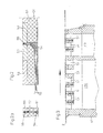
- the squeegee 51 shown in Figures 2 and 2a consists of a support plate 52, on the top of which a plurality of ceramic plates 53 are attached.
- the support plate 52 is formed with a recess in which a temperature sensor 54 is arranged, the sensor element 55 of which is located in one of the ceramic plates 53.
- the measured values determined by the sensor element 55 are output via a line 56.
- Thermocouples with the material pairing FE-CuNi according to DIN 43 710, class 2 or NiCr-Ni according to DIN EN 60 584 class 2 are preferably used as temperature sensors. Platinum resistors according to DIN IEC 751 can also be used
- FIG 3 shows the suction box 41. As can be seen from this, this is Suction box in two vacuum areas 41a and 41b with different ones Suction effects divided. In this suction box 41 there are several with Wiper strips 51 designed for temperature sensors.
- the temperatures occurring in these due to the friction of the sieve belts 1 and 2 compared to the scraper strips 51 are measured, which are evaluated in the evaluation unit 40.
- the valves 71, 72 and 73 located in the water inlet 60 to the spray nozzles 61, 62 and 63 can be controlled via the lines 71 a, 72a and 73a and, on the other hand, the control of the valves in FIG the valves 81, 82 and 83 located to the suction boxes 41, 42 and 43 leading vacuum line 80 take place.
- the valves 71, 72 and 73 control the action of the coolant, in particular water, on the sieve belts 1 and 2 or the scraper strips 51. In this way, overheating of the ceramic squeegees 51 and, on the other hand, damaging effects of thermal shocks can be avoided.
- the control unit 70 can control the discharge of the pulp from the device 3 between the sieve belts 1 and 2. This is advantageous because if the scraper strips overheat, the pulp can cause a temperature shock, which is prevented if no pulp is discharged.
- each with at least one temperature sensor is formed by which the temperatures occurring in the squeegees be measured.
- These measured values can be sent to a display device be performed, followed by manual control of the supply of coolant and / or the suction effect of the suction boxes and a control of the discharge of the pulp can be made.
- These measured values can also can also be guided to a control unit through which a program-controlled Regulation of the supply of coolant and / or the suction effect the suction boxes and the discharge of the pulp can take place.
Landscapes
- Paper (AREA)
Abstract
Description
- Fig. 1
- eine erfindungsgemäße Anlage, in schematischer Darstellung;
- Fig.2 und 2a
- eine mit einem Temperatursensor ausgebildete keramische Abstreifleiste, im Längsschnitt und im Querschnitt; und
- Fig.3
- einen mit Abstreifleisten gemäß den Fig.2 und 2a ausgebildeten Saugkasten im Schnitt.
Ein weiterer Ausgang 30a der Regeleinheit 70 ist an ein Ventil 31 gelegt, welches sich in einer Zuleitung 30 zur Vorrichtung 3 für das Aufbringen des Stoffbreis befindet.
Als Temperatursensoren werden vorzugsweise Thermoelemente mit der Materialpaarung FE-CuNi nach DIN 43 710, Kl. 2 bzw. NiCr-Ni nach DIN EN 60 584 Kl. 2 eingesetzt. Weiters können auch Platin-Widerstände nach DIN IEC 751 eingesetzt werden
Zudem kann durch die Regeleinheit 70 die Ausbringung des Stoffbreis aus der Vorrichtung 3 zwischen die Siebbänder 1 und 2 gesteuert werden. Dies ist deshalb vorteilhaft, da bei einer Überhitzung der Abstreifleisten durch den Stoffbrei ein Temperaturschock verursacht werden kann, welcher dann verhindert wird, wenn kein Stoffbrei ausgetragen wird.
Claims (5)
- Anlage zur Erzeugung eines Papierbandes (10) mit mindestens einem über Trag- bzw. Führungswalzen (11, 12) bewegten, in sich geschlossenen Siebband [1, 2), mit einer Vorrichtung (3) zur Aufbringung eines Stoffbreis auf das Siebband (1, 2), mit längs des Siebbandes (1, 2) angeordneten Saugeinrichtungen (41, 42, 43) sowie keramische Abstreifleisten (44, 51) und gegebenenfalls mit Einrichtungen (61, 62, 63) zur durch Ventile (71, 72, 73) gesteuerten Beaufschlagung (41, 42, 43) des Siebbandes (1, 2) bzw. der Abstreifleisten (44, 51) mit einem Kühlmittel, insbesondere mit Wasser, dadurch gekennzeichnet, daß zumindest ein Teil der Abstreifleisten (44, 51) mit mindestens einem Temperatursensor (54) ausgebildet ist, dessen Ausgang an eine Anzeigeeinrichtung bzw. an eine Regeleinheit (70) gelegt ist.
- Anlage nach Patentanspruch 1, dadurch gekennzeichnet, daß Ausgänge (71a, 72a, 73a) der Regeleinheit (70) an die Steuerventile (71, 72, 73) der Einrichtungen [61, 62, 63) zur Beaufschlagung des Siebbandes (1, 2) bzw. der Abstreifleisten (51) mit dem Kühlmittel gelegt sind.
- Anlage nach einem der Patentansprüche 1 und 2, dadurch gekennzeichnet, daß Ausgänge [81a, 82a, 83a) der Regeleinheit (70) an den Saugeinrichtungen (41, 42, 43) zugeordnete Regelventile (81, 82, 83) gelegt sind.
- Anlage nach einem der Patentansprüche 1 bis 3, dadurch gekennzeichnet, daß ein Ausgang (30a) der Regeleinheit (70) an die Vorrichtung (3) des Austrages für den Stoffbrei auf das Siebband (1, 2) gelegt ist.
- Anlage nach einem der Patentansprüche 1 bis 4, dadurch gekennzeichnet, daß die Saugeinrichtungen (41, 42, 43) mit mindestens einer keramischen Abstreifleiste (51) mit mindestens einem Temperatursensor (54) ausgebildet sind, dessen Ausgang über die Regeleinheit (70) an das Steuerventil (71, 72, 73) der dem betreffenden Saugkasten (41, 42, 43) zugeordneten Einrichtung zur Beaufschlagung des Siebbandes (1, 2) bzw. der Abstreifleisten (51) mit dem Kühlmittel gelegt ist.
Applications Claiming Priority (2)
| Application Number | Priority Date | Filing Date | Title |
|---|---|---|---|
| AT10852002 | 2002-07-18 | ||
| AT0108502A AT411536B (de) | 2002-07-18 | 2002-07-18 | Anlage zur erzeugung eines papierbandes mit mindestens einem über trag- bzw. führungswalzen bewegten, in sich geschlossenen siebband |
Publications (2)
| Publication Number | Publication Date |
|---|---|
| EP1382741A2 true EP1382741A2 (de) | 2004-01-21 |
| EP1382741A3 EP1382741A3 (de) | 2004-08-18 |
Family
ID=3685199
Family Applications (1)
| Application Number | Title | Priority Date | Filing Date |
|---|---|---|---|
| EP03450022A Withdrawn EP1382741A3 (de) | 2002-07-18 | 2003-01-23 | Anlage zur Erteugung eines Papierbandes mit mindestens einemuber Trag-bzw. Fuhrungswalzen bewegten, in sich geschlossenen Siebband |
Country Status (5)
| Country | Link |
|---|---|
| US (1) | US6884322B2 (de) |
| EP (1) | EP1382741A3 (de) |
| JP (1) | JP4125171B2 (de) |
| AT (1) | AT411536B (de) |
| CA (1) | CA2424349C (de) |
Cited By (2)
| Publication number | Priority date | Publication date | Assignee | Title |
|---|---|---|---|---|
| EP1845189A3 (de) * | 2006-04-13 | 2008-04-30 | Heinz Bartelmuss | Verfahren zur Steuerung der Temperatur der keramischen Elemente einer Abstütz- bzw. Abstreifleiste in einer Anlage zur Papiererzeugung sowie Einrichtung und Abstütz- bzw. Abstreifleiste zur Durchführung dieses Verfahrens |
| WO2020052833A1 (de) * | 2018-09-14 | 2020-03-19 | Voith Patent Gmbh | Formierpartie und betriebsverfahren |
Families Citing this family (3)
| Publication number | Priority date | Publication date | Assignee | Title |
|---|---|---|---|---|
| KR100717530B1 (ko) | 2005-06-23 | 2007-05-11 | 안상록 | 내마모성 물질로 코팅된 종이 코팅액 스크레이핑 작업용메탈 바 |
| CN101310073B (zh) * | 2005-11-16 | 2011-11-02 | 株式会社堀河制作所 | 带传感器脱水板、脱水板装置 |
| JP4636620B2 (ja) * | 2005-11-16 | 2011-02-23 | 株式会社堀河製作所 | センサ付脱水フォイル、脱水フォイル装置及び紙の製造方法 |
Family Cites Families (6)
| Publication number | Priority date | Publication date | Assignee | Title |
|---|---|---|---|---|
| US4055459A (en) * | 1976-06-28 | 1977-10-25 | Jwi Ltd. | Method and apparatus for preventing the adherence of polarized foreign particles to paper machine components |
| DE3128866A1 (de) * | 1981-07-22 | 1983-02-10 | Feldmühle AG, 4000 Düsseldorf | Papiermaschine |
| US6274002B1 (en) * | 1998-06-23 | 2001-08-14 | Wilbanks International, Inc. | Papermaking machine with variable dewatering elements including variable pulse turbulation blades adjusted by computer control system in response to sensors of paper sheet characteristics |
| US6290816B1 (en) * | 1999-07-21 | 2001-09-18 | Voith Sulzer Paper Technology North America, Inc. | Paper machine with closed loop control system |
| DE10123529A1 (de) * | 2001-05-15 | 2002-11-21 | Voith Paper Patent Gmbh | Verfahren und System zur Überwachung eines Entwässerungselements |
| EP1260633B1 (de) * | 2001-05-15 | 2007-02-21 | Voith Patent GmbH | Maschine zur Herstellung einer Faserstoffbahn aus einer Faserstoffsuspension, Verfahren zur Überwachung eines Entwässerungselements einer Papiermaschine und Papiermaschine mit einem System zur Überwachung eines Entwässerungselements |
-
2002
- 2002-07-18 AT AT0108502A patent/AT411536B/de not_active IP Right Cessation
-
2003
- 2003-01-23 EP EP03450022A patent/EP1382741A3/de not_active Withdrawn
- 2003-04-02 US US10/405,848 patent/US6884322B2/en not_active Expired - Lifetime
- 2003-04-02 CA CA002424349A patent/CA2424349C/en not_active Expired - Lifetime
- 2003-04-10 JP JP2003106635A patent/JP4125171B2/ja not_active Expired - Lifetime
Cited By (2)
| Publication number | Priority date | Publication date | Assignee | Title |
|---|---|---|---|---|
| EP1845189A3 (de) * | 2006-04-13 | 2008-04-30 | Heinz Bartelmuss | Verfahren zur Steuerung der Temperatur der keramischen Elemente einer Abstütz- bzw. Abstreifleiste in einer Anlage zur Papiererzeugung sowie Einrichtung und Abstütz- bzw. Abstreifleiste zur Durchführung dieses Verfahrens |
| WO2020052833A1 (de) * | 2018-09-14 | 2020-03-19 | Voith Patent Gmbh | Formierpartie und betriebsverfahren |
Also Published As
| Publication number | Publication date |
|---|---|
| CA2424349C (en) | 2007-09-18 |
| ATA10852002A (de) | 2003-07-15 |
| JP4125171B2 (ja) | 2008-07-30 |
| US6884322B2 (en) | 2005-04-26 |
| AT411536B (de) | 2004-02-25 |
| CA2424349A1 (en) | 2004-01-18 |
| EP1382741A3 (de) | 2004-08-18 |
| US20040011491A1 (en) | 2004-01-22 |
| JP2004052207A (ja) | 2004-02-19 |
Similar Documents
| Publication | Publication Date | Title |
|---|---|---|
| DE3213249A1 (de) | Verfahren und vorrichtung zum unterdruecken einer luftschicht zwischen einer gutbahn und einer von dieser umschlungenen walze | |
| AT394739B (de) | Vorrichtung zur entwaesserung einer zellstoffbahn bzw. einer materialbahn fuer eine pappenerzeugung | |
| EP3887138A1 (de) | Vorrichtung zur pressenden bearbeitung von flachmaterial | |
| EP0073915B1 (de) | Verfahren und Vorrichtung zur Kontrolle der kontinuierlichen Wärmebehandlung einer textilen Warenbahn | |
| DE112010003058T5 (de) | Gehäuse für eine inerte Umgebung | |
| EP0157403A2 (de) | Verfahren und Anlage zum Trocknen einer mit härtbarem Kunstharz imprägnierten Warenbahn | |
| AT411536B (de) | Anlage zur erzeugung eines papierbandes mit mindestens einem über trag- bzw. führungswalzen bewegten, in sich geschlossenen siebband | |
| EP3902670B1 (de) | Kontinuierlich arbeitende presse mit vorrichtung zur überwachung des schmierzustandes eines mit schmiermittel beaufschlagten umlaufenden bandes und entsprechendes verfahren | |
| EP0771903B1 (de) | Verfahren und Vorrichtung zur Behandlung einer Faserstoff- oder Papierbahn | |
| EP2350360B1 (de) | Verfahren und vorrichtung zur herstellung von strangförmigen waren | |
| DE102017108108B4 (de) | Kontinuierlich arbeitende Presse mit einer Reinigungsvorrichtung und Verfahren zum Betreiben einer kontinuierlich arbeitenden Presse | |
| EP1431435B1 (de) | Vorrichtung für die Ablage und Förderung einer Vliesbahn aus Kunststofffäden | |
| EP1260633A2 (de) | Maschine zur Herstellung einer Faserstoffbahn aus einer Faserstoffsuspension sowie Verfahren und System zur Überwachung eines Entwässerungselements | |
| DE3743933A1 (de) | Verfahren und vorrichtung zur beheizung einer kontinuierlich arbeitenden heizplattenpresse | |
| EP1449958B1 (de) | Vorrichtung zur Behandlung insbesondere zur Unterdruck-Beaufschlagung, des in einer Anlage zur Papiererzeugung vorgesehenen im Umlauf bewgten mindestens einen Siebbandes bzw. Filzbandes | |
| DE2702112B2 (de) | Verfahren und Vorrichtung zum · automatischen oder halbautomatischen Trennen von abgepaßten textlien Stoffteilen | |
| DE29720892U1 (de) | Vorrichtung für das Erwärmen und Auftragen plastischer Massen | |
| DE3877885T2 (de) | Vorrichtung zum fortlaufenden reinigen der nadeln eines nadelstabstreckwerkes fuer textilfasern. | |
| DE10163575A1 (de) | Maschine zur Herstellung einer Faserstoffbahn aus einer Faserstoffsuspension | |
| DE19740858C1 (de) | Filterbandtrockner | |
| CH280046A (de) | Fördereinrichtung für Bahnen aus Papier, Zellulosefilz, Gewebe oder dergleichen. | |
| DE3235710C2 (de) | Vorrichtung zum kontinuierlichen Vulkanisieren von strang- oder bahnförmigen Kautschukartikeln | |
| DE19633656C1 (de) | Vorrichtung zum ein- oder beidseitigen Benetzen von flexiblen Trägerwerkstoffen | |
| EP0078528A2 (de) | Abstreifvorrichtung für weichflexibles Flachmaterial, insbesondere Leder von der Arbeitsfläche einer Bügelwalze | |
| DE10123529A1 (de) | Verfahren und System zur Überwachung eines Entwässerungselements |
Legal Events
| Date | Code | Title | Description |
|---|---|---|---|
| PUAI | Public reference made under article 153(3) epc to a published international application that has entered the european phase |
Free format text: ORIGINAL CODE: 0009012 |
|
| AK | Designated contracting states |
Kind code of ref document: A2 Designated state(s): AT BE BG CH CY CZ DE DK EE ES FI FR GB GR HU IE IT LI LU MC NL PT SE SI SK TR |
|
| AX | Request for extension of the european patent |
Extension state: AL LT LV MK RO |
|
| PUAL | Search report despatched |
Free format text: ORIGINAL CODE: 0009013 |
|
| AK | Designated contracting states |
Kind code of ref document: A3 Designated state(s): AT BE BG CH CY CZ DE DK EE ES FI FR GB GR HU IE IT LI LU MC NL PT SE SI SK TR |
|
| AX | Request for extension of the european patent |
Extension state: AL LT LV MK RO |
|
| 17P | Request for examination filed |
Effective date: 20041019 |
|
| AKX | Designation fees paid |
Designated state(s): AT BE BG CH CY CZ DE DK EE ES FI FR GB GR HU IE IT LI LU MC NL PT SE SI SK TR |
|
| 17Q | First examination report despatched |
Effective date: 20050607 |
|
| STAA | Information on the status of an ep patent application or granted ep patent |
Free format text: STATUS: THE APPLICATION IS DEEMED TO BE WITHDRAWN |
|
| 18D | Application deemed to be withdrawn |
Effective date: 20051220 |