EP1382766A2 - Kit pour les constructions en treillis assemblables - Google Patents
Kit pour les constructions en treillis assemblables Download PDFInfo
- Publication number
- EP1382766A2 EP1382766A2 EP03013240A EP03013240A EP1382766A2 EP 1382766 A2 EP1382766 A2 EP 1382766A2 EP 03013240 A EP03013240 A EP 03013240A EP 03013240 A EP03013240 A EP 03013240A EP 1382766 A2 EP1382766 A2 EP 1382766A2
- Authority
- EP
- European Patent Office
- Prior art keywords
- kit
- girder
- pair
- walls
- lattice
- Prior art date
- Legal status (The legal status is an assumption and is not a legal conclusion. Google has not performed a legal analysis and makes no representation as to the accuracy of the status listed.)
- Granted
Links
Images







Classifications
-
- E—FIXED CONSTRUCTIONS
- E04—BUILDING
- E04B—GENERAL BUILDING CONSTRUCTIONS; WALLS, e.g. PARTITIONS; ROOFS; FLOORS; CEILINGS; INSULATION OR OTHER PROTECTION OF BUILDINGS
- E04B9/00—Ceilings; Construction of ceilings, e.g. false ceilings; Ceiling construction with regard to insulation
- E04B9/04—Ceilings; Construction of ceilings, e.g. false ceilings; Ceiling construction with regard to insulation comprising slabs, panels, sheets or the like
- E04B9/0428—Ceilings; Construction of ceilings, e.g. false ceilings; Ceiling construction with regard to insulation comprising slabs, panels, sheets or the like having a closed frame around the periphery
-
- E—FIXED CONSTRUCTIONS
- E04—BUILDING
- E04B—GENERAL BUILDING CONSTRUCTIONS; WALLS, e.g. PARTITIONS; ROOFS; FLOORS; CEILINGS; INSULATION OR OTHER PROTECTION OF BUILDINGS
- E04B7/00—Roofs; Roof construction with regard to insulation
- E04B7/02—Roofs; Roof construction with regard to insulation with plane sloping surfaces, e.g. saddle roofs
- E04B7/022—Roofs; Roof construction with regard to insulation with plane sloping surfaces, e.g. saddle roofs consisting of a plurality of parallel similar trusses or portal frames
-
- E—FIXED CONSTRUCTIONS
- E04—BUILDING
- E04B—GENERAL BUILDING CONSTRUCTIONS; WALLS, e.g. PARTITIONS; ROOFS; FLOORS; CEILINGS; INSULATION OR OTHER PROTECTION OF BUILDINGS
- E04B7/00—Roofs; Roof construction with regard to insulation
- E04B7/02—Roofs; Roof construction with regard to insulation with plane sloping surfaces, e.g. saddle roofs
- E04B7/04—Roofs; Roof construction with regard to insulation with plane sloping surfaces, e.g. saddle roofs supported by horizontal beams or the equivalent resting on the walls
-
- E—FIXED CONSTRUCTIONS
- E04—BUILDING
- E04B—GENERAL BUILDING CONSTRUCTIONS; WALLS, e.g. PARTITIONS; ROOFS; FLOORS; CEILINGS; INSULATION OR OTHER PROTECTION OF BUILDINGS
- E04B7/00—Roofs; Roof construction with regard to insulation
- E04B7/02—Roofs; Roof construction with regard to insulation with plane sloping surfaces, e.g. saddle roofs
- E04B7/06—Constructions of roof intersections or hipped ends
-
- E—FIXED CONSTRUCTIONS
- E04—BUILDING
- E04B—GENERAL BUILDING CONSTRUCTIONS; WALLS, e.g. PARTITIONS; ROOFS; FLOORS; CEILINGS; INSULATION OR OTHER PROTECTION OF BUILDINGS
- E04B9/00—Ceilings; Construction of ceilings, e.g. false ceilings; Ceiling construction with regard to insulation
- E04B9/06—Ceilings; Construction of ceilings, e.g. false ceilings; Ceiling construction with regard to insulation characterised by constructional features of the supporting construction, e.g. cross section or material of framework members
-
- E—FIXED CONSTRUCTIONS
- E04—BUILDING
- E04C—STRUCTURAL ELEMENTS; BUILDING MATERIALS
- E04C3/00—Structural elongated elements designed for load-supporting
- E04C3/02—Joists; Girders, trusses, or trusslike structures, e.g. prefabricated; Lintels; Transoms; Braces
- E04C3/04—Joists; Girders, trusses, or trusslike structures, e.g. prefabricated; Lintels; Transoms; Braces of metal
- E04C3/08—Joists; Girders, trusses, or trusslike structures, e.g. prefabricated; Lintels; Transoms; Braces of metal with apertured web, e.g. with a web consisting of bar-like components; Honeycomb girders
-
- E—FIXED CONSTRUCTIONS
- E04—BUILDING
- E04C—STRUCTURAL ELEMENTS; BUILDING MATERIALS
- E04C3/00—Structural elongated elements designed for load-supporting
- E04C3/02—Joists; Girders, trusses, or trusslike structures, e.g. prefabricated; Lintels; Transoms; Braces
- E04C3/04—Joists; Girders, trusses, or trusslike structures, e.g. prefabricated; Lintels; Transoms; Braces of metal
- E04C3/11—Joists; Girders, trusses, or trusslike structures, e.g. prefabricated; Lintels; Transoms; Braces of metal with non-parallel upper and lower edges, e.g. roof trusses
-
- E—FIXED CONSTRUCTIONS
- E04—BUILDING
- E04C—STRUCTURAL ELEMENTS; BUILDING MATERIALS
- E04C5/00—Reinforcing elements, e.g. for concrete; Auxiliary elements therefor
- E04C5/01—Reinforcing elements of metal, e.g. with non-structural coatings
- E04C5/06—Reinforcing elements of metal, e.g. with non-structural coatings of high bending resistance, i.e. of essentially three-dimensional [3D] extent, e.g. lattice girders
- E04C5/065—Light-weight girders, e.g. with precast parts
-
- E—FIXED CONSTRUCTIONS
- E04—BUILDING
- E04B—GENERAL BUILDING CONSTRUCTIONS; WALLS, e.g. PARTITIONS; ROOFS; FLOORS; CEILINGS; INSULATION OR OTHER PROTECTION OF BUILDINGS
- E04B7/00—Roofs; Roof construction with regard to insulation
- E04B7/02—Roofs; Roof construction with regard to insulation with plane sloping surfaces, e.g. saddle roofs
- E04B7/06—Constructions of roof intersections or hipped ends
- E04B7/063—Hipped ends
Definitions
- the present invention relates to a kit for building composable "trellis-like" or lattice structures of the type comprising the features set out in the preamble of claim 1.
- kits consisting of prefabricated lattice girders are used, typically made of galvanized steel.
- the lattice girders are joined to each other and to bearing structures such as pillars, main girders or walls of the building that they must cover, by means of connecting plates fastened with bolts, nails, etc. Subsequently panels, roofing tile-carrying laths or other covering elements are applied to the framework formed of said girders.
- kits comprising lattice girders consisting of two pairs of round steel bars, or steel rods, extending along respective longitudinal axes and spaced apart by appropriate connecting rods consecutively disposed in an alternated course.
- the girders are transversely connected with other girders, in particular with ridgepoles, through transverse superposition of the respective pairs of round bars thereon. More particularly, the girders are joined by four U-shaped plates each disposed on either side of a respective pair of round bars, pierced with holes for passage of a joining bolt capable of tightening the pairs themselves on each other.
- Lattices of the above described type presently can be exclusively used as a support for covering elements, in combination with main girders provided with greater flexional and torsional stiffness.
- main girders have a substantially triangular section and are substantially formed of two lattice girders of the above described type 'disposed longitudinally in side by side relationship along one of the two pairs of round bars and extending transversely of each other.
- Girders of this type are connected with support pillars by junction members formed of a plate butt-resting against the ends of the round bars and carrying three lugs, one at each girder vertex, joined to the girder by bolts passing both through the lugs and the two round bars of each pair.
- the Applicant has thought of using the lattice girders both as a support for the covering elements and as main girders to reduce the typology of the elements to be used and increase the modular character and flexibility of use of the kit.
- Another aim of the invention is to devise a kit for building composable lattice structures of easy and quick assembling/disassembling.
- a kit for building composable lattice structures in accordance with the invention is generally identified by reference numeral 1.
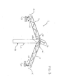
- Kit 1 comprises a plurality of lattice girders 2, preferably made of hot galvanized steel, which extend along respective longitudinal axes X.
- each of the girders 2 has a first pair 3 of round bars or rods, 3a, 3b, disposed in parallel side by side relationship along the longitudinal axis X of the girder 2 itself.
- the first pair 3 of round bars 3a, 3b is fastened, by a plurality of connecting rods 4, to a second pair 5 of round bars 5a, 5b quite similar to the first pair 3.
- the round bars 5a, 5b of the second pair 5 too are mutually parallel and extend along the longitudinal axis X of girder 2.
- the connecting rods 4 space out the two pairs 3, 5 to give girder 2 a suitable bending stiffness in the plane defined by the rods 4 themselves.
- the round bars 3a, 3b; 5a, 5b of each pair 3, 5 are also spaced apart from each other, to form a hollow space 6 between them in which an end of each connecting rod 4 is rigidly engaged, preferably by welding (Figs. 4-7a).
- rods 4 are diagonally disposed between the first 3 and second 5 pairs and consecutively one after the other, to form a zigzag succession.
- the ends of two consecutive rods 4 lie in side by side relationship between two round bars 3a, 3b; 5a, 5b of the lattice girder 2.
- Girders 2 can be engaged with one or more bearing structures 7.
- the bearing structure 7 is defined by a ridgepole 8, of the H type (IPE) for example, fastened to the walls of the building to be covered.
- the bearing structure is a support pillar 9 from which girders 2 extend radially away, to build pergolas and gazebos, for example.
- girders 2 can be directly joined together to obtain support frameworks with different configurations.
- kit 1 For connection between girders 2, and between the girders 2 and bearing structures 7, kit 1 further comprises a plurality of junction elements 10 associable with respective hooking elements 11.
- Each of the junction elements 10 can be engaged with one end 2a of a girder 2.
- each junction element 10 has a box-shaped structure 12 defined by a plurality of side walls 12a, 12b, 12c, 12d that, after mounting on girder 2, surround the extremity 2a, 2b of the girder 2 itself.
- the junction element 10 comprises four walls 12a, 12b, 12c, 12d that are opposite two by two. Two contiguous walls 12a, 12c; 12b, 12d form a right angle.
- a first pair of mutually opposite walls 12a, 12b is associated, in contact relationship, with one of the two pairs of round bars 3, 5, while a second pair of walls 12c, 12d extends in a transverse direction between the walls of the first pair 12a, 12b.
- the walls 12a, 12b of the first pair have at least one first 13a and one second 13b openings, one on each wall 12a, 12b, to house at least two connecting elements 14 of known type, a pair of bolts for example (Figs. 4 and 4a).
- Openings 13a, 13b face the hollow space 6 defined between two round bars 3a, 3b; 5a, 5b disposed side by side, so that each bolt 14 can be suitably positioned between said round bars 3a, 3b; 5a, 5b in order to lock the junction element 10 to girder 2.
- the first 13a and second 13b openings have an elongated shape so that several bolts 14 can be received, or insertion of at least one bolt can take place also close to the regions where, between the round bars 3a, 3b; 5a, 5b, the ends of the connecting rods 4 are rigidly engaged.
- the walls 12c, 12d of the second pair have at least one first 15c and one second 15d holes, one on each wall 12c, 12d.
- the two holes 15c, 15d are coaxial so that one connecting element 14, typically one bolt, can be introduced into both of them to carry out a connection between the junction element 10 and one of said hooking devices 11.
- each of the hooking devices 11 comprises a plate-like element 16 to be engaged, by known connection means, to one of the bearing structures 7, a ridgepole 8 for example.
- a tubular body 17 (Fig. 5a) is rigidly connected with the plate-like element 16 and is insertable between the second pair of walls 12c, 12d, coaxially with the first and second holes 15c, 15d, to receive the connecting element 14.
- the tubular body 17 is removably in engagement with the plate-like element 16.
- the tubular body 17 is movable in parallel to the plate-like element 16 between a first and a second positions.
- the hooking device 11 has a tailpiece 18 extending away from the plate-like element 16, preferably in a direction perpendicular thereto.
- a through hole 18a, formed in the tailpiece 18, enables housing of a stem 19 carrying the tubular body 17 at an end 19a thereof.
- stem 19 is inserted in the through hole 18a and is caused to slide therein until the tubular body 17 is brought to the desired position.
- the tubular body 17 is fastened to the tailpiece 18 by suitable locking means 20.
- stem 19 is a threaded stem and screwed thereon is a nut 20a and a lock nut 20b, placed on opposite sides relative to the tailpiece 18, which nuts therefore define the locking means 20.
- each junction element 10 is associated with the support pillar 9 through a hooking capital 60, to form the bearing structure shown in Figs. 2 and 3.
- capital 60 comprises a circular plate 61 to be rigidly mounted to the upper end of pillar 9 and provided with a central hole 62 through which a threaded stem 63 is passed.
- Capital 60 further has a cup-shaped element 64 having a circular base associable with plate 61 and the concavity of which faces the plate 61 itself.
- the cup-shaped element 64 too has a central hole 65 within which the threaded stem 63 is placed.
- a plurality of connecting bodies 65 each having a prismatic portion 65a provided with a through hole 66 and a cylindrical tailpiece 67 insertable in the concavity of the cup-shaped element 64.
- Stem 19 is fastened, with said nut 20a and lock nut 20b, in the through hole 66 and each of the connecting bodies 65 is locked to capital 60 by tightening the cup-shaped element 64 on the circular plate 61 with a respective nut 68a and lock nut 68b (Fig. 3).
- Fig. 7 shows a third embodiment in which each of the junction elements 10 has a pair of parallel plates 21a-, 21b, provided with respective through holes 22a, 22b. Plates 21a, 21b extend away from the first and second pairs of walls 12a, 12b, 12c, 12d.
- the parallel plates 21a, 21b are placed close to the walls of the first pair 12a, 12b and extend parallel thereto, along the longitudinal axis X of the girder 2 on which the hooking element 10 is mounted to enable butt-connection of a girder 2 with the respective hooking element 11.
- the hooking device 11 comprises a tubular element 23 to be coaxially disposed between the through holes 22a, 22b of the pair of parallel plates 21a, 21b for housing of a connecting element, typically a bolt in this case too (not shown), which is operatively in engagement both with the parallel plates 21a, 21b and the hooking device 11.
- the longitudinal extension of the tubular element 23 is smaller than the distance between the two plates 21a, 21b.
- the distance between the two plates 21a, 21b is substantially the same as the sum of the tubular element 23 length and the thickness of one plate 21a, 21b.
- the hooking device 11 in accordance with the third embodiment allows two girders 2 to be butt-connected.
- two girders 2 provided each with a junction element 10 having the pair of parallel plates 21a, 21b are butt-approached with association of plates 21a, 21b in such a manner that the four through holes 22a, 22b are positioned in coaxial relationship.
- tubular element 23 is coaxially disposed between the through holes 22a, 22b of the four plates 21a, 21b and joined thereto by a bolt (Fig. 7a).
- the tubular element 23 further comprises a tailpiece 24 extending away from the tubular element and provided with a through hole 25.
- Tailpiece 24 enables connection to the tubular element 23 of a third girder 2 equipped with a junction element 10 in accordance with the first or second embodiment.
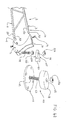
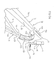
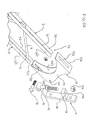
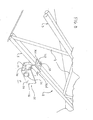
- kit 1 further comprises a rest device 25 (Figs. 8 and 9).
- the rest device 25 comprises a base 26 to be rigidly engaged with the wall P of a building and an adjustable element 27 to be mounted on girder 2 and associable with base 26.
- the base 26 of the rest device 25 has a U-shaped conformation in section, which defines two mutually parallel walls 28 extending in a transverse direction from a base wall 29 put in contact with the building wall P.
- auxiliary tubular body 30 Rotatably inserted between the walls 28 of base 26 is an auxiliary tubular body 30 being part of the adjustable element 27.
- the auxiliary tubular body 30 is linked to base 26 by a pin 31 inserted in suitable through holes 32 formed in the mutually parallel walls 28 and in the auxiliary tubular body itself 30.
- the adjustable element 27 further comprises a threaded pin 33 integral with the auxiliary tubular body 30 which is inserted between two round bars 3a, 3b; 5a, 5b of one of the two pairs of round bars 3, 5 of girder 2.
- the adjustable element 27 also comprises a first nut 34a and a second nut 34b and two respective plates 34c, 34d disposed on a first side and a second side opposite to the first one respectively, of the pair of round bars 3, 5 of girder 2.
- the adjustable elements 27 are fastened to the building wall P, subsequently pins 33 are inserted between the round bars 3a, 3b; 5a, 5b of the respective girders 2 and finally after positioning girders 2 to the desired height, said pins 33 are locked to girders 2 by said nut and lock nut 34a, 34b.
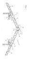
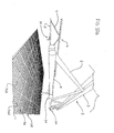
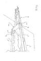
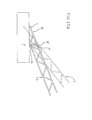
- kit 1 in accordance with the present invention further comprises at least one first flat netlike support element 35 having a first plurality of meshes 35a and a second flat netlike element 36 having a second plurality of meshes 36a (Figs. 10 and 10a).
- the two netlike elements 35, 36 can be engaged with several lattice girders 2, through appropriate fastening means 37, at the lower portion of the lattice structure for example, to perform the function of supporting one or more plaster layers.
- the meshes 35a of the first flat netlike element 35 disposed directly in contact with girders 2 are larger than the meshes 36a of the second flat netlike element 36 that is associated in contact relationship with the first flat netlike element 35 on the opposite side with respect to girders 2.
- the second flat netlike element 36 with thicker meshes ensures setting of the plaster, whereas the first flat netlike element 35 that is stronger carries out stiffening of the structure.
- the two netlike elements 35, 36 can also be suitably shaped and fastened to both the structure and the walls, to make particular moulded members, as used in shaped cornices for example (Fig. 10b).
- the fastening means 37 comprises a first plurality of auxiliary plates 38 connected to the lattice girders 2 by connecting means 39 of known type.
- the connecting means 39 of known type, bolts for example, are inserted both in the auxiliary plates 38 and the round bars 3a, 3b; 5a, 5b of the respective girders 2.
- Each of the auxiliary plates 38 has a tailpiece 38a which is deformable between a first position at which said tailpiece 38a lies in a transverse direction to the respective auxiliary plate 38, and a second position at which the tailpiece 38a lies parallel to the respective auxiliary plate 38 to clamp the first 35 and second 36 flat netlike elements superposed on each other, between the tailpiece itself and the plate.
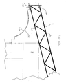
- kit 1 in accordance with the present invention further comprises a second plurality of auxiliary plates 50, each of them being susceptible of abutment against a respective girder 2 for butt-connection with an auxiliary girder 41.
- each auxiliary plate belonging to the second plurality has two lugs 42 extending perpendicular from the plate 40 itself and associable with the two pairs of round bars 3, 5.
- an opening for housing at least two connecting elements 14 is formed in each of the two lugs 42 following the construction diagram already depicted for the junction element 10.
- the openings of each lug 42 face the hollow space 6 defined between two round bars disposed side by side 3a, 3b; 5a, 5b, so that each connecting element 14 may be suitably positioned between the round bars themselves 3a, 3b; 5a, 5b to lock lug 42 on girder 2.
- the auxiliary girder 31 is joined to the plate 40 of the second plurality by butt-welding the round bars 3,5 of the auxiliary girder 41 to the plate 40 itself.
- the auxiliary girder 41 has smaller transverse sizes than the main girders 2.
- the distance between pairs of round bars 3, 5 of the auxiliary girders 41 is smaller than the distance between the corresponding pairs of the main girders 2.
- This type of auxiliary girders 41 is used to make the side projections of the lattice structure beyond the building walls P, so as to form the roof portion currently called gutter.
- the auxiliary girder 41 is an end girder or stanchion, terminating at the building wall P or alternatively directly to the ground.
- the end girder 41 has one pair alone of upper round bars 3 that are mutually parallel and butt-associated, through the auxiliary plate of the second plurality 40, with the upper round rods of a main girder 2.
- the round bars 3 of the end girder 41 are also supported by a connecting rod 4 connected to the auxiliary plate 40.
- the round bars 3 of the end girder 41 are cut to size during mounting of the structure, based on inclination of the main girders 2 and bulkiness of the structure itself.
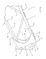
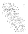
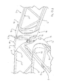
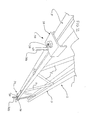
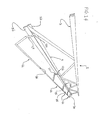
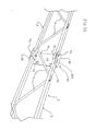
- Kit 1 further comprises a plurality of support members 44 for hollow tiles T to be engaged with the lattice girders 2 (Figs. 14 and 15) that, like the flat netlike elements 35, 36, can be associated with several lattice girders 2 at the lower portion of the lattice structure.
- each of the support members 44 has a hooking portion 45 susceptible of engagement with the round bars 3a, 3b, 5a, 5b of one of the pairs 3, 5 of round bars and a rest surface 46 transversely extending from the lattice girder 2 for support of at least one hollow tile.
- the support member 44 is defined by a U-shaped auxiliary round bar the end portions 44a of which define the hooking portion 45.
- each of the end portions 44a defines a hook 47 to be inserted between the round bars 3a, 3b, 5a, 5b of one of the pairs 3, 5.
- hook 47 has a first stretch 47a, a second stretch 47b consecutively in engagement with the first one 47a, and a third stretch 47c consecutively in engagement with the second one 47b.
- the third stretch 47c is connected to the rest surface 46.
- the second stretch 47b lies in a transverse direction between the first 47a and third stretches whereas the first stretch 47a and third stretch 47c are parallel to each other and mutually spaced by a distance substantially corresponding to the diameter of one of the round bars 3a, 3b; 5a, 5b.
- the first stretch 47a rests at the bottom against one of the round bars 3a; 3b, 5a; 5b of a pair, while the third stretch 47c rests at the top against the second round bar 3b; 3a, 5b; 5a of the same pair 3, 5, the second stretch 47b passing between the two round bars 3a, 3b; 5a, 5b.
- auxiliary plates 48 are provided, each of them being of a U-shaped configuration for engagement along the longitudinal extension of a lattice girder 2.
- each plate of the third plurality 48 has a central body 49 and two tailpieces 50 extending from opposite edges 49a of the central body 49 and transversely thereof.
- central body 49 Formed in the central body 49 is one or more through holes 51 for engagement with conventional connecting means not shown, the function of which is to join the lattice girder 2, at intermediate points thereof, to a wall or other bearing structures.
- Plate 48 is fastened to the lattice girder 2 by screws or bolts inserted in a slot 52 formed in each tailpiece 50 that, when plate 48 is mounted on girder 2, faces the hollow space 6 defined between the round bars 3a, 3b, 5a, 5b of the girder 2 itself, and by counter-elements 53 associated with each pair of round bars 3a, 3b, 5a, 5b on the opposite side from the tailpiece 50.
- the invention achieves important advantages.
- the kit for building composable lattice structures in accordance with the present invention enables light-in-weight and strong structures to be made because it uses as the modular elements, simple lattices with a low weight/capacity load ratio.
- kit for building composable lattice structures in accordance with the present invention enables said structures to be made with ease and rapidity.
- all the elements are bolted to each other, no drilling or welding operations are required for erection of the kit.
- kit in accordance with the present invention enables geometrically complex constructions to be made which may also be very different from each other, using the same base elements.
- junction elements of the present kit are very versatile because they enable mutual connections to be made between girders, between the girders and bearing structures and between the girders and covering elements.
- the hollow space defined between two round bars disposed side by side of each lattice girder enables fittings for covering and false ceiling to be easily bolted at any point along the girder itself.
- the particular junction elements being the object of the present invention which are disposed at the girder ends allow severe measuring operations of the lattice length during building and laying to be avoided.
- kit in accordance with the invention enables fine adjustment of the relative position between the different elements.
- the elements constituting the present kit are simple and inexpensive because they are adapted to be mass produced.
Landscapes
- Engineering & Computer Science (AREA)
- Architecture (AREA)
- Civil Engineering (AREA)
- Structural Engineering (AREA)
- Physics & Mathematics (AREA)
- Electromagnetism (AREA)
- Joining Of Building Structures In Genera (AREA)
- Rod-Shaped Construction Members (AREA)
- Organic Low-Molecular-Weight Compounds And Preparation Thereof (AREA)
- Display Devices Of Pinball Game Machines (AREA)
- Memory System Of A Hierarchy Structure (AREA)
- Information Transfer Systems (AREA)
- Breeding Of Plants And Reproduction By Means Of Culturing (AREA)
- Orthopedics, Nursing, And Contraception (AREA)
- Golf Clubs (AREA)
Priority Applications (1)
| Application Number | Priority Date | Filing Date | Title |
|---|---|---|---|
| SI200331145T SI1382766T1 (sl) | 2002-07-12 | 2003-06-12 | Komplet sestavnih delov za gradnjo sestavljive palične strukture |
Applications Claiming Priority (2)
| Application Number | Priority Date | Filing Date | Title |
|---|---|---|---|
| ITMI20021534 | 2002-07-12 | ||
| IT2002MI001534A ITMI20021534A1 (it) | 2002-07-12 | 2002-07-12 | Corredo per la realizzazione di strutture tralicciate componibili |
Publications (3)
| Publication Number | Publication Date |
|---|---|
| EP1382766A2 true EP1382766A2 (fr) | 2004-01-21 |
| EP1382766A3 EP1382766A3 (fr) | 2005-09-28 |
| EP1382766B1 EP1382766B1 (fr) | 2007-12-12 |
Family
ID=29765338
Family Applications (1)
| Application Number | Title | Priority Date | Filing Date |
|---|---|---|---|
| EP03013240A Expired - Lifetime EP1382766B1 (fr) | 2002-07-12 | 2003-06-12 | Kit pour les constructions en treillis assemblables |
Country Status (6)
| Country | Link |
|---|---|
| EP (1) | EP1382766B1 (fr) |
| AT (1) | ATE380907T1 (fr) |
| DE (1) | DE60317978T2 (fr) |
| ES (1) | ES2297076T3 (fr) |
| IT (1) | ITMI20021534A1 (fr) |
| SI (1) | SI1382766T1 (fr) |
Cited By (2)
| Publication number | Priority date | Publication date | Assignee | Title |
|---|---|---|---|---|
| GB2413568A (en) * | 2004-04-27 | 2005-11-02 | David Creighton Mcveigh | Roof structure |
| CN1873151B (zh) * | 2006-06-30 | 2010-11-24 | 上海浦飞尔金属吊顶有限公司 | 用于建筑物吊顶的拉杆装置 |
Families Citing this family (1)
| Publication number | Priority date | Publication date | Assignee | Title |
|---|---|---|---|---|
| CN106869389A (zh) * | 2017-03-31 | 2017-06-20 | 北京善筑科技股份有限公司 | 坡屋面连接件及具有该连接件的装配式建筑坡屋面体系 |
Family Cites Families (10)
| Publication number | Priority date | Publication date | Assignee | Title |
|---|---|---|---|---|
| US1727893A (en) * | 1926-09-29 | 1929-09-10 | Fredellia H Moyer | Steel joist |
| GB387317A (en) * | 1930-06-23 | 1933-02-02 | David Jacobus Van Rijsinge | Method for the manufacture of a ceiling |
| US3180461A (en) * | 1960-10-10 | 1965-04-27 | Unicel Corp | Building clips |
| DE2314866A1 (de) * | 1972-03-30 | 1974-02-14 | Straub Siegfried | Verbindungssystem |
| DE2600602A1 (de) * | 1975-01-31 | 1976-08-05 | Betschart Anton Peter Dipl Ing | Tragsystem |
| AT333479B (de) * | 1975-04-04 | 1976-11-25 | Wallner Matthias | Verbindungsbauteil fur bedachungen, abdeckungen od.dgl. |
| US4253210A (en) * | 1979-09-10 | 1981-03-03 | Andre Racicot | Metal truss structure |
| FR2556759B1 (fr) * | 1983-12-16 | 1986-04-11 | Chamayou Gerard | Elements de faux-plafond et faux-plafond a treillis, notamment lumineux, realise a partir de tels elements |
| DE3936665C2 (de) * | 1989-11-03 | 1994-04-28 | Babar S A | Deckenverkleidung |
| US5697195A (en) * | 1995-03-07 | 1997-12-16 | Alabama Metal Industries Corporation | Plaster security barrier system |
-
2002
- 2002-07-12 IT IT2002MI001534A patent/ITMI20021534A1/it unknown
-
2003
- 2003-06-12 AT AT03013240T patent/ATE380907T1/de not_active IP Right Cessation
- 2003-06-12 ES ES03013240T patent/ES2297076T3/es not_active Expired - Lifetime
- 2003-06-12 EP EP03013240A patent/EP1382766B1/fr not_active Expired - Lifetime
- 2003-06-12 SI SI200331145T patent/SI1382766T1/sl unknown
- 2003-06-12 DE DE60317978T patent/DE60317978T2/de not_active Expired - Lifetime
Cited By (2)
| Publication number | Priority date | Publication date | Assignee | Title |
|---|---|---|---|---|
| GB2413568A (en) * | 2004-04-27 | 2005-11-02 | David Creighton Mcveigh | Roof structure |
| CN1873151B (zh) * | 2006-06-30 | 2010-11-24 | 上海浦飞尔金属吊顶有限公司 | 用于建筑物吊顶的拉杆装置 |
Also Published As
| Publication number | Publication date |
|---|---|
| EP1382766A3 (fr) | 2005-09-28 |
| ATE380907T1 (de) | 2007-12-15 |
| ES2297076T3 (es) | 2008-05-01 |
| ITMI20021534A1 (it) | 2004-01-12 |
| EP1382766B1 (fr) | 2007-12-12 |
| DE60317978D1 (de) | 2008-01-24 |
| DE60317978T2 (de) | 2008-12-18 |
| SI1382766T1 (sl) | 2008-06-30 |
Similar Documents
| Publication | Publication Date | Title |
|---|---|---|
| EP3085844B1 (fr) | Ossature en acier léger tridimensionnelle formée par des poutres doubles continues à deux voies | |
| US5306210A (en) | Louvre type roof structures | |
| US4349996A (en) | Integrated roof system | |
| CZ260993A3 (en) | Building panel with a metal-sheet structural element | |
| US20030177735A1 (en) | Built-up beam assembly for building structures | |
| US4809480A (en) | Building metal support apparatus and method | |
| US4733508A (en) | Multi-sided building construction | |
| US3422591A (en) | Composite truss joist with offset bearing | |
| EP1382766B1 (fr) | Kit pour les constructions en treillis assemblables | |
| US3314209A (en) | Composite truss joist having chords and links of adjustable angle | |
| US8539730B2 (en) | Building system | |
| JP2009102844A (ja) | 金属製建屋、屋根材ユニット及びジョイント部材 | |
| US8763317B2 (en) | Concrete roof panel | |
| WO2007143375A2 (fr) | Structure dotÉe de plusieurs ÉlÉments structurels entrelacÉs dont la rÉsistance À des forces multidirectionnelles est amÉliorÉe | |
| RU2188287C2 (ru) | Покрытие из трехгранных ферм | |
| US3313070A (en) | Composite structural pillar and rafter beams with nailing strips | |
| KR0178690B1 (ko) | 철근 콘크리트 슬래브의 데크 거어더 및 데크 패널 | |
| JP3955492B2 (ja) | ユニット式建物およびユニット式建物の施工方法 | |
| WO1983000714A1 (fr) | Elements de parois portants et constructions comprenant de tels elements | |
| JP7569204B2 (ja) | 玄関ポーチ | |
| GB2413568A (en) | Roof structure | |
| US2682940A (en) | Building construction | |
| JP2009174121A (ja) | 位置決め金物及びこれを用いた屋根面材 | |
| WO2005007983A1 (fr) | Connecteur de construction, etrier a solive, packer de ventilation et procede de construction de batiment | |
| RU2627794C1 (ru) | Покрытие из трехгранных ферм |
Legal Events
| Date | Code | Title | Description |
|---|---|---|---|
| PUAI | Public reference made under article 153(3) epc to a published international application that has entered the european phase |
Free format text: ORIGINAL CODE: 0009012 |
|
| AK | Designated contracting states |
Kind code of ref document: A2 Designated state(s): AT BE BG CH CY CZ DE DK EE ES FI FR GB GR HU IE IT LI LU MC NL PT RO SE SI SK TR |
|
| AX | Request for extension of the european patent |
Extension state: AL LT LV MK |
|
| RIC1 | Information provided on ipc code assigned before grant |
Ipc: 7E 04B 9/06 B Ipc: 7E 04C 3/11 A Ipc: 7E 04C 3/08 B Ipc: 7E 04C 5/065 B Ipc: 7E 04B 7/06 B Ipc: 7E 04B 7/02 B |
|
| PUAL | Search report despatched |
Free format text: ORIGINAL CODE: 0009013 |
|
| RIC1 | Information provided on ipc code assigned before grant |
Ipc: 7E 04C 5/065 B Ipc: 7E 04C 3/04 B Ipc: 7E 04B 7/06 B Ipc: 7E 04F 13/04 B Ipc: 7E 04C 3/08 B Ipc: 7E 04B 7/02 B Ipc: 7E 04B 9/06 B Ipc: 7E 04C 3/11 A |
|
| AK | Designated contracting states |
Kind code of ref document: A3 Designated state(s): AT BE BG CH CY CZ DE DK EE ES FI FR GB GR HU IE IT LI LU MC NL PT RO SE SI SK TR |
|
| AX | Request for extension of the european patent |
Extension state: AL LT LV MK |
|
| 17P | Request for examination filed |
Effective date: 20060327 |
|
| AKX | Designation fees paid |
Designated state(s): AT BE BG CH CY CZ DE DK EE ES FI FR GB GR HU IE IT LI LU MC NL PT RO SE SI SK TR |
|
| 17Q | First examination report despatched |
Effective date: 20070206 |
|
| GRAP | Despatch of communication of intention to grant a patent |
Free format text: ORIGINAL CODE: EPIDOSNIGR1 |
|
| RAP1 | Party data changed (applicant data changed or rights of an application transferred) |
Owner name: POLIMENI S.R.L. |
|
| GRAS | Grant fee paid |
Free format text: ORIGINAL CODE: EPIDOSNIGR3 |
|
| GRAA | (expected) grant |
Free format text: ORIGINAL CODE: 0009210 |
|
| AK | Designated contracting states |
Kind code of ref document: B1 Designated state(s): AT BE BG CH CY CZ DE DK EE ES FI FR GB GR HU IE IT LI LU MC NL PT RO SE SI SK TR |
|
| REG | Reference to a national code |
Ref country code: GB Ref legal event code: FG4D |
|
| REG | Reference to a national code |
Ref country code: CH Ref legal event code: EP |
|
| REG | Reference to a national code |
Ref country code: IE Ref legal event code: FG4D |
|
| REF | Corresponds to: |
Ref document number: 60317978 Country of ref document: DE Date of ref document: 20080124 Kind code of ref document: P |
|
| REG | Reference to a national code |
Ref country code: RO Ref legal event code: EPE |
|
| REG | Reference to a national code |
Ref country code: GR Ref legal event code: EP Ref document number: 20080400477 Country of ref document: GR |
|
| REG | Reference to a national code |
Ref country code: CH Ref legal event code: NV Representative=s name: ISLER & PEDRAZZINI AG |
|
| PG25 | Lapsed in a contracting state [announced via postgrant information from national office to epo] |
Ref country code: SE Free format text: LAPSE BECAUSE OF FAILURE TO SUBMIT A TRANSLATION OF THE DESCRIPTION OR TO PAY THE FEE WITHIN THE PRESCRIBED TIME-LIMIT Effective date: 20080312 |
|
| REG | Reference to a national code |
Ref country code: ES Ref legal event code: FG2A Ref document number: 2297076 Country of ref document: ES Kind code of ref document: T3 |
|
| PG25 | Lapsed in a contracting state [announced via postgrant information from national office to epo] |
Ref country code: NL Free format text: LAPSE BECAUSE OF FAILURE TO SUBMIT A TRANSLATION OF THE DESCRIPTION OR TO PAY THE FEE WITHIN THE PRESCRIBED TIME-LIMIT Effective date: 20071212 Ref country code: FI Free format text: LAPSE BECAUSE OF FAILURE TO SUBMIT A TRANSLATION OF THE DESCRIPTION OR TO PAY THE FEE WITHIN THE PRESCRIBED TIME-LIMIT Effective date: 20071212 |
|
| NLV1 | Nl: lapsed or annulled due to failure to fulfill the requirements of art. 29p and 29m of the patents act | ||
| PG25 | Lapsed in a contracting state [announced via postgrant information from national office to epo] |
Ref country code: AT Free format text: LAPSE BECAUSE OF FAILURE TO SUBMIT A TRANSLATION OF THE DESCRIPTION OR TO PAY THE FEE WITHIN THE PRESCRIBED TIME-LIMIT Effective date: 20071212 |
|
| PG25 | Lapsed in a contracting state [announced via postgrant information from national office to epo] |
Ref country code: CZ Free format text: LAPSE BECAUSE OF FAILURE TO SUBMIT A TRANSLATION OF THE DESCRIPTION OR TO PAY THE FEE WITHIN THE PRESCRIBED TIME-LIMIT Effective date: 20071212 |
|
| ET | Fr: translation filed | ||
| PG25 | Lapsed in a contracting state [announced via postgrant information from national office to epo] |
Ref country code: SK Free format text: LAPSE BECAUSE OF FAILURE TO SUBMIT A TRANSLATION OF THE DESCRIPTION OR TO PAY THE FEE WITHIN THE PRESCRIBED TIME-LIMIT Effective date: 20071212 Ref country code: BE Free format text: LAPSE BECAUSE OF FAILURE TO SUBMIT A TRANSLATION OF THE DESCRIPTION OR TO PAY THE FEE WITHIN THE PRESCRIBED TIME-LIMIT Effective date: 20071212 |
|
| PG25 | Lapsed in a contracting state [announced via postgrant information from national office to epo] |
Ref country code: PT Free format text: LAPSE BECAUSE OF FAILURE TO SUBMIT A TRANSLATION OF THE DESCRIPTION OR TO PAY THE FEE WITHIN THE PRESCRIBED TIME-LIMIT Effective date: 20080512 |
|
| PLBE | No opposition filed within time limit |
Free format text: ORIGINAL CODE: 0009261 |
|
| STAA | Information on the status of an ep patent application or granted ep patent |
Free format text: STATUS: NO OPPOSITION FILED WITHIN TIME LIMIT |
|
| PG25 | Lapsed in a contracting state [announced via postgrant information from national office to epo] |
Ref country code: DK Free format text: LAPSE BECAUSE OF FAILURE TO SUBMIT A TRANSLATION OF THE DESCRIPTION OR TO PAY THE FEE WITHIN THE PRESCRIBED TIME-LIMIT Effective date: 20071212 |
|
| 26N | No opposition filed |
Effective date: 20080915 |
|
| PG25 | Lapsed in a contracting state [announced via postgrant information from national office to epo] |
Ref country code: MC Free format text: LAPSE BECAUSE OF NON-PAYMENT OF DUE FEES Effective date: 20080630 |
|
| PG25 | Lapsed in a contracting state [announced via postgrant information from national office to epo] |
Ref country code: BG Free format text: LAPSE BECAUSE OF FAILURE TO SUBMIT A TRANSLATION OF THE DESCRIPTION OR TO PAY THE FEE WITHIN THE PRESCRIBED TIME-LIMIT Effective date: 20080312 Ref country code: EE Free format text: LAPSE BECAUSE OF FAILURE TO SUBMIT A TRANSLATION OF THE DESCRIPTION OR TO PAY THE FEE WITHIN THE PRESCRIBED TIME-LIMIT Effective date: 20071212 |
|
| PG25 | Lapsed in a contracting state [announced via postgrant information from national office to epo] |
Ref country code: CY Free format text: LAPSE BECAUSE OF FAILURE TO SUBMIT A TRANSLATION OF THE DESCRIPTION OR TO PAY THE FEE WITHIN THE PRESCRIBED TIME-LIMIT Effective date: 20071212 |
|
| PG25 | Lapsed in a contracting state [announced via postgrant information from national office to epo] |
Ref country code: LU Free format text: LAPSE BECAUSE OF NON-PAYMENT OF DUE FEES Effective date: 20080612 Ref country code: HU Free format text: LAPSE BECAUSE OF FAILURE TO SUBMIT A TRANSLATION OF THE DESCRIPTION OR TO PAY THE FEE WITHIN THE PRESCRIBED TIME-LIMIT Effective date: 20080613 |
|
| PG25 | Lapsed in a contracting state [announced via postgrant information from national office to epo] |
Ref country code: IT Free format text: LAPSE BECAUSE OF NON-PAYMENT OF DUE FEES Effective date: 20080630 |
|
| PGFP | Annual fee paid to national office [announced via postgrant information from national office to epo] |
Ref country code: TR Payment date: 20140522 Year of fee payment: 12 |
|
| REG | Reference to a national code |
Ref country code: FR Ref legal event code: PLFP Year of fee payment: 13 |
|
| PGFP | Annual fee paid to national office [announced via postgrant information from national office to epo] |
Ref country code: SI Payment date: 20150626 Year of fee payment: 13 Ref country code: GB Payment date: 20150630 Year of fee payment: 13 Ref country code: CH Payment date: 20150629 Year of fee payment: 13 |
|
| PGFP | Annual fee paid to national office [announced via postgrant information from national office to epo] |
Ref country code: GR Payment date: 20150629 Year of fee payment: 13 Ref country code: IE Payment date: 20150629 Year of fee payment: 13 |
|
| PGFP | Annual fee paid to national office [announced via postgrant information from national office to epo] |
Ref country code: ES Payment date: 20150722 Year of fee payment: 13 Ref country code: RO Payment date: 20150720 Year of fee payment: 13 Ref country code: DE Payment date: 20150831 Year of fee payment: 13 |
|
| PGFP | Annual fee paid to national office [announced via postgrant information from national office to epo] |
Ref country code: FR Payment date: 20150630 Year of fee payment: 13 |
|
| REG | Reference to a national code |
Ref country code: DE Ref legal event code: R119 Ref document number: 60317978 Country of ref document: DE |
|
| PG25 | Lapsed in a contracting state [announced via postgrant information from national office to epo] |
Ref country code: RO Free format text: LAPSE BECAUSE OF NON-PAYMENT OF DUE FEES Effective date: 20160612 |
|
| REG | Reference to a national code |
Ref country code: CH Ref legal event code: PL |
|
| GBPC | Gb: european patent ceased through non-payment of renewal fee |
Effective date: 20160612 |
|
| REG | Reference to a national code |
Ref country code: GR Ref legal event code: ML Ref document number: 20080400477 Country of ref document: GR Effective date: 20170109 |
|
| REG | Reference to a national code |
Ref country code: IE Ref legal event code: MM4A |
|
| REG | Reference to a national code |
Ref country code: SI Ref legal event code: KO00 Effective date: 20170228 Ref country code: FR Ref legal event code: ST Effective date: 20170228 |
|
| PG25 | Lapsed in a contracting state [announced via postgrant information from national office to epo] |
Ref country code: FR Free format text: LAPSE BECAUSE OF NON-PAYMENT OF DUE FEES Effective date: 20160630 Ref country code: DE Free format text: LAPSE BECAUSE OF NON-PAYMENT OF DUE FEES Effective date: 20170103 Ref country code: CH Free format text: LAPSE BECAUSE OF NON-PAYMENT OF DUE FEES Effective date: 20160630 Ref country code: LI Free format text: LAPSE BECAUSE OF NON-PAYMENT OF DUE FEES Effective date: 20160630 Ref country code: GR Free format text: LAPSE BECAUSE OF NON-PAYMENT OF DUE FEES Effective date: 20170109 |
|
| PG25 | Lapsed in a contracting state [announced via postgrant information from national office to epo] |
Ref country code: SI Free format text: LAPSE BECAUSE OF NON-PAYMENT OF DUE FEES Effective date: 20160613 Ref country code: GB Free format text: LAPSE BECAUSE OF NON-PAYMENT OF DUE FEES Effective date: 20160612 Ref country code: IE Free format text: LAPSE BECAUSE OF NON-PAYMENT OF DUE FEES Effective date: 20160612 |
|
| PG25 | Lapsed in a contracting state [announced via postgrant information from national office to epo] |
Ref country code: ES Free format text: LAPSE BECAUSE OF NON-PAYMENT OF DUE FEES Effective date: 20160613 |
|
| REG | Reference to a national code |
Ref country code: ES Ref legal event code: FD2A Effective date: 20181203 |
|
| PG25 | Lapsed in a contracting state [announced via postgrant information from national office to epo] |
Ref country code: TR Free format text: LAPSE BECAUSE OF NON-PAYMENT OF DUE FEES Effective date: 20160612 |