EP1382806B1 - Procédé et installation pour utiliser des déchets dans une centrale thermoelectrique - Google Patents
Procédé et installation pour utiliser des déchets dans une centrale thermoelectrique Download PDFInfo
- Publication number
- EP1382806B1 EP1382806B1 EP03009305A EP03009305A EP1382806B1 EP 1382806 B1 EP1382806 B1 EP 1382806B1 EP 03009305 A EP03009305 A EP 03009305A EP 03009305 A EP03009305 A EP 03009305A EP 1382806 B1 EP1382806 B1 EP 1382806B1
- Authority
- EP
- European Patent Office
- Prior art keywords
- combustion
- waste
- plant
- power station
- air
- Prior art date
- Legal status (The legal status is an assumption and is not a legal conclusion. Google has not performed a legal analysis and makes no representation as to the accuracy of the status listed.)
- Expired - Lifetime
Links
Images




Classifications
-
- B—PERFORMING OPERATIONS; TRANSPORTING
- B09—DISPOSAL OF SOLID WASTE; RECLAMATION OF CONTAMINATED SOIL
- B09B—DISPOSAL OF SOLID WASTE NOT OTHERWISE PROVIDED FOR
- B09B3/00—Destroying solid waste or transforming solid waste into something useful or harmless
- B09B3/60—Biochemical treatment, e.g. by using enzymes
-
- F—MECHANICAL ENGINEERING; LIGHTING; HEATING; WEAPONS; BLASTING
- F01—MACHINES OR ENGINES IN GENERAL; ENGINE PLANTS IN GENERAL; STEAM ENGINES
- F01K—STEAM ENGINE PLANTS; STEAM ACCUMULATORS; ENGINE PLANTS NOT OTHERWISE PROVIDED FOR; ENGINES USING SPECIAL WORKING FLUIDS OR CYCLES
- F01K3/00—Plants characterised by the use of steam or heat accumulators, or intermediate steam heaters, therein
- F01K3/18—Plants characterised by the use of steam or heat accumulators, or intermediate steam heaters, therein having heaters
- F01K3/24—Plants characterised by the use of steam or heat accumulators, or intermediate steam heaters, therein having heaters with heating by separately-fired heaters
- F01K3/247—Plants characterised by the use of steam or heat accumulators, or intermediate steam heaters, therein having heaters with heating by separately-fired heaters one heater being an incinerator
-
- F—MECHANICAL ENGINEERING; LIGHTING; HEATING; WEAPONS; BLASTING
- F23—COMBUSTION APPARATUS; COMBUSTION PROCESSES
- F23G—CREMATION FURNACES; CONSUMING WASTE PRODUCTS BY COMBUSTION
- F23G5/00—Incineration of waste; Incinerator constructions; Details, accessories or control therefor
- F23G5/006—General arrangement of incineration plant, e.g. flow sheets
-
- F—MECHANICAL ENGINEERING; LIGHTING; HEATING; WEAPONS; BLASTING
- F23—COMBUSTION APPARATUS; COMBUSTION PROCESSES
- F23G—CREMATION FURNACES; CONSUMING WASTE PRODUCTS BY COMBUSTION
- F23G5/00—Incineration of waste; Incinerator constructions; Details, accessories or control therefor
- F23G5/44—Details; Accessories
- F23G5/46—Recuperation of heat
-
- F—MECHANICAL ENGINEERING; LIGHTING; HEATING; WEAPONS; BLASTING
- F23—COMBUSTION APPARATUS; COMBUSTION PROCESSES
- F23G—CREMATION FURNACES; CONSUMING WASTE PRODUCTS BY COMBUSTION
- F23G2206/00—Waste heat recuperation
- F23G2206/20—Waste heat recuperation using the heat in association with another installation
- F23G2206/203—Waste heat recuperation using the heat in association with another installation with a power/heat generating installation
-
- Y—GENERAL TAGGING OF NEW TECHNOLOGICAL DEVELOPMENTS; GENERAL TAGGING OF CROSS-SECTIONAL TECHNOLOGIES SPANNING OVER SEVERAL SECTIONS OF THE IPC; TECHNICAL SUBJECTS COVERED BY FORMER USPC CROSS-REFERENCE ART COLLECTIONS [XRACs] AND DIGESTS
- Y02—TECHNOLOGIES OR APPLICATIONS FOR MITIGATION OR ADAPTATION AGAINST CLIMATE CHANGE
- Y02E—REDUCTION OF GREENHOUSE GAS [GHG] EMISSIONS, RELATED TO ENERGY GENERATION, TRANSMISSION OR DISTRIBUTION
- Y02E20/00—Combustion technologies with mitigation potential
- Y02E20/12—Heat utilisation in combustion or incineration of waste
Definitions
- This invention relates to the field of waste disposal in general, and to a method and a plant for generation of electric energy using solid waste in particular. Such a method and plant are known from document EP-A-0 399 104 for example.
- SW solid waste such as that originating from non-selective collection, waste originating from selective collection, fractions containing fermentable material separated from said waste, biomasses originating from "set-aside” land, and biomasses contained in refuse or waste originating from other agricultural and/or industrial processes or from purification of effluent containing a fermentable organic fraction.
- SW or at least a fraction thereof, to obtain energy, generally electrical energy, which is not necessarily usable in situ and is available for local distribution.
- Said methods basically involve combustion of waste, which may be crushed and treated in advance, in a fluidized bed reactor which transfers heat to pressurized water with production of steam that expands in a turbine driving an electrical energy generator in accordance with the known technique in the field.
- thermodynamic efficiency of around 25%, namely approx. 50% of the efficiency of conventional thermal power stations.
- Said low efficiency is due to a number of factors, the most important being the size of the incinerating plant, which is relatively small compared with that of thermal power stations.
- the quantity of energy obtainable from the waste produced in a given area is one or two orders of magnitude smaller than that consumed in the same area.
- European patent no. 706839 describes a method for the production of SF with a high net heat value which uses the fermentation heat of the putrescible fraction present in the SW to be treated as energy for the evaporation of water. Fractions with an inorganic base, which produce ash during combustion, are separated. As the weight of the SF thus treated is approx. 50% of the original weight, and its lower heat value is more than twice that of the SW input, a waste preparation process of the type mentioned above makes it possible to concentrate approx. four times the energy contained in the original untreated waste.
- ITS intelligent transfer stations
- Italian patent no. 1297234 describes a method and an apparatus for the preparation and transport of SF to the end user.
- thermal power stations do not use solid fuel, but fluid or fluidized materials. Even when coal is used, it is pulverized in advance with mills (that cannot be used for SFs, which have the opposite physical grinding characteristics to coal) and fed to the combustion chamber in the form of fluidized dust.
- Methods which recover energy from waste, in particular from treated SW or SFs, by gasification of secondary fuels, in order to obtain a combustible fluid that can be used to feed existing thermal power stations.
- the fluid originating from the gasifiers is obtained by partial combustion of the prepared waste or secondary fuel, and contains carbon dioxide, carbon monoxide, light hydrocarbons, heavy pitches, ash and acid products in addition to the nitrogen in the air used.
- purification of this fluid is very difficult.
- the heavy constituents of the fluid are deposited on the surfaces and clog the filters; in the case of wet purification, difficulties are involved in subsequent purification of the aqueous effluent and disposal of the residues, together with loss of the sensible heat of the fluids obtained.
- the main purpose of this invention is to eliminate said drawbacks by providing a method and plant for the use of SW or SF in large thermal power stations able to generate electrical energy simply and cleanly, with high thermodynamic efficiency.
- a further purpose is to maximize the electrical energy obtained from SW or residual fractions after separate collection by means of production and combustion of secondary fuel (SF).
- SF secondary fuel
- Another purpose is to provide a method and plant which enable the thermal energy provided by SW or SF to be recovered in thermal power station boilers in the form of a substantially clean fluid.
- a further purpose is to provide a method and plant which allow existing sites to be used to install plants for the production of energy from SW, and in particular from SF.
- a further purpose is to provide a method and plant for incineration with cogeneration of electrical energy from waste, prepared waste or secondary fuels which is simple, cheap and easy to run.
- Said method is characterized in that it includes waste combustion with a suitably controlled air flow so that combustion is approximately complete, cooling of the burnt gases by at least partial mixing with cold air until they reach a pre-determined temperature which is lower than the maximum temperature compatible with gas cleaning, cleaning of the cooled burnt gases, and mixing of said cooled burnt gases with the combustion air used in the power station so as to transfer all their thermal energy content to said combustion air, at the same time preventing the problems of ash deposit and formation of pollutants.
- a plant for implementation of said method comprises means for the preparation of waste for combustion, means for combustion of the waste in the presence of a controlled air flow regulated to obtain approximately complete combustion of the waste, means for cooling the burnt gas to a temperature lower than the maximum temperature compatible with gas cleaning, means for cleaning said cooled, burnt gases, and means for mixing said cooled burnt gases with the combustion air used in the power station so as to transfer their thermal energy content to said combustion air, at the same time preventing the problems of ash deposit and formation of pollutants.
- This method and plant make it possible to fuel a thermal power station with a clean fluid devoid of particulate matter which complies with environmental regulations for flue gases.
- the method and plant according to the invention allow the use of gas-cleaning equipments operating at a relatively low temperature which are already known and tested, and have a relatively low cost. Moreover, total combustion of secondary fuels at a high temperature, with a surplus of air, prevents the production of micropollutants.
- the waste combustion plant according to the invention does not include the related thermoelectric heat cycle for the production of electrical energy, and is integrated with a large, usually existing combustion plant, the investment involved is far less than that required for a SF combustion plant with production of electrical energy.
- the method and plant according to this invention also solve the considerable problems involved in the choice of location of a SF combustion plant, because the plant according to this invention is an auxiliary plant of an existing plant which is 20 to 50 times larger.
- the annexed figures illustrate a plant for the use of SW according to the invention, globally indicated by the reference number 1 , which can be associated with a thermal power station, globally indicated by reference number 100 , operating either inside it or in an independent unit.
- thermal power station 100 the primary energy is supplied by the combustion of fossil fuels with air and partial recirculation of combustion gases in order to reduce NOx.
- power station 100 can include a boiler unit 2 in which fossil fuels are burned and pressurized steam is produced, a power-generating unit 3 that comprises a turbine in which expansion of steam takes place that drives an alternator for electric energy generation, a line 4 that feeds pressurized steam to generating unit 3 , and a line 5 for the return of condensate to boiler unit 2 .
- the combustion air from the environment is conveyed to the combustion system of boiler unit 2 , passing through a line 6 , a gas/gas exchanger 7 where it is preheated by the flue gases to a temperature Tc , a line 8 , a mixer 9 where the recycled flow 13 is added, and a line 10 .
- the flow of hot gases that exit the boiler 2 after steam generation is conveyed to a pipe or line 11 and then distributed along two more lines 12 and 13 .
- line 12 By means of line 12 , most of the flow of hot gases passes through gas/gas exchanger 7 , a line 14 , and a dust removal and cleaning system 15 , and is then discharged into the atmosphere through the stack 16 .
- the oxygen content of the combustion air is reduced to values close to 18%, so as to limit the adiabatic flame temperature and NOx formation.
- Thermal power station 100 may be a standardized unit with a power of 320 MW, which consumes 75000 Nm3/h of natural gas (methane) with a mean conversion efficiency to electricity of nearly 40% on an annual basis, net of internal consumption.
- Gas/gas exchanger 7 consequently plays a crucial role in the efficiency of energy transformation and the reduction of the energy released to the flue in the form of sensible heat, approx. 15-16% of the global energy involved being recovered.
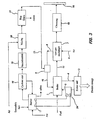
- Plant 1 for the use of waste according to the invention which can operate in association with thermal power station 100 , operates on the basis of the following method, schematically illustrated in FIG. 2 .
- the waste initially undergoes a combustion stage a) with a suitably controlled air flow so that combustion is approximately complete.
- the burnt gases are then cooled b) by at least partial mixing with cold air until they reach pre-determined temperature Tw , which is lower than the maximum temperature compatible with the cleaning system.
- the cooled burnt gases undergo a cleaning stage c) , followed by mixing d) with the combustion air used in the power station, so as to transfer the majority of their thermal energy to the combustion air.
- Waste combustion will preferably take place without an excess of air, or with a pre-determined air excess.
- the air excess is between 0% and 60% of the stoichiometric ratio.
- the burnt gas is cleaned until the content of dust, inorganic acid compounds, condensed polycyclic aromatic compounds and chlorinated organic compounds falls below pre-determined values.
- Activated coal dust is added to trap condensed or chlorinated aromatic compounds.
- the burnt gases have a relatively low oxygen content, they can at least partly replace the recirculated combustion gases used in power station 100 to reduce NOx formation, as already mentioned.
- the thermal energy of the coolant fluid is provided by means of a suitable heat exchange f) to the water recycled to the thermal power station boiler, or another possible form of use.
- the burnt gases can be partly cooled in a boiler, not shown in the figures, installed downstream of the waste combustion chamber to generate hot water or superheated steam.
- the SW is pre-treated g) to make a secondary fuel SF before its combustion.
- said pre-treatment or preparation g) can include extraction of the putrescible fraction of the waste, of metals and of aggregates.
- the putrescible fraction extraction stage comprises a stage of forced aerobic fermentation of the waste with air sucked through it in a closed environment.
- This treatment produces a secondary fuel SF with a water content of under 20% in weight, a lower heat value of about 17000 kJ/kg (4000 kcal/kg) of dry matter, and a bacteria count of under 1000 N/g.
- plant 1 for implementation of the method of use of SW described above comprises means for preparation of the waste for combustion, means for combustion of the waste in the presence of a controlled air flow regulated to obtain approximately total combustion and to produce a burnt gas, means for cooling the burnt gas to a temperature lower than the maximum temperature compatible with the filters and higher than the minimum temperature of the combustion air of the power station, means for cleaning the mixture of gases, and means for mixing the cleaned burnt gas with the combustion air in the combustion chamber of power station 100 .
- the waste preparation means can be constituted by coarse crushing means, means of aerobic fermentation of the putrescible fraction, means for extraction of metals with electrical and/or magnetic fields and sieving means for extracting aggregates.
- the combustion means designed to effect substantially total combustion of the waste comprise a combustion chamber 17 , a cyclone unit 18 and a post-treatment chamber 19 .
- combustion chamber 17 can be the fluidised-bed type operating with sand, magnesium carbonate and dolomite at temperatures of between 700°C and 900°C, and preferably close to 850°C, cooled by circulation of a coolant fluid such as pressurized water and steam.
- a coolant fluid such as pressurized water and steam.
- the burnt gases can be neutralised in a post-treatment chamber 19 with soda in solution, soda vapor, or magnesium and calcium oxides, to eliminate the sulphur and chlorine not retained in the fluidized bed by the neutralising agents present.
- the means for cooling burnt gases comprise a mixer 20 in which the burnt gases are mixed with atmospheric air to produce a mixture of gases that is easy to clean.
- Temperature Tw is reduced to values of between 200°C and 500°C, and preferably close to 430°C.
- said cooling means could include an exchanger incorporated in the SF combustion chamber so that burnt gasses are emitted from said combustion chamber at a temperature of between 400 and 850°C, and preferably close to the lowest values required by cleaning, thus reducing the mixing air flow.
- the means for cleaning the burnt gases before they are conveyed to thermal power station 100 could be a bag filter 21 .
- the filtration fabric could be fibreglass able to operate at temperatures of up to 400°C.
- activated carbon dust not shown in the annexed figures can be introduced before filtration to adsorb condensed aromatic compounds and chlorinated compounds.
- the cleaned burnt gas thus obtained is low in oxygen, devoid of particular matter, inorganic acid compounds and low-boiling organic compounds, and complies with environmental regulations for flue emissions.
- the means of introducing cleaned burnt gas as part of the combustion gas into the combustion chamber of boiler 2 of power station 100 , regulated to at least partly replace combustion burnt gases recycle to reduce NOx, comprise a line 23 whereby the cleaned burnt gas is conveyed to the thermal power station and a mixer 9 in which it is combined with the preheated combustion air in gas/gas exchanger 7 .
- this gas is produced by combustion, it is low in oxygen and can perform the function of limiting the adiabatic flame temperature in a similar way to partial recycling of the products of combustion, as schematically illustrated in FIG. 1 .
- the pressurized hot fluid obtained from fluidized-bed cooling circuit 17 could be used to preheat the water 5 recycled to boiler unit 2 of the thermal power station by means of a suitable exchanger 24 .
- the usable quantity of SF is limited by the fact that the quantity of oxygen in the combustion air at the combustion chamber of boiler 2 of the thermal production line must be close to 18%, and its temperature under 400°C.
- the quantity of energy supplied ranges between 3 and 10% of the electrical energy produced, depending on the technology of the power station in which the invention is used.
- the flow of cleaned burnt gas sent via line 23 is divided into a flow sent to mixer 9 and a flow sent via line 26 to line 11 prior to gas/gas exchanger 7 .
- the production of cleaned burnt gas will be higher than in the case of mixing with combustion air for combustion in boiler unit 2 of thermal power station 100 , without disturbing its operation, for example during operation at a reduced load due to lower energy demand from the network at night or on non-working days, or due to the need to dispose of a larger amount of waste.
- the air preheated in exchanger 7 which is surplus to combustion needs in boiler unit 2 is sent via line 27 to an exchanger 25 for further heating of the water recycle to boiler 2 , and subsequently to the stack 16 .
- a plant for the combustion of secondary fuel which is able to burn 13 t/h of secondary fuel with production after air dilution and filtration of approx. 258 t/h of cleaned burnt gas at the temperature of 430°C and with an oxygen concentration of around 14% is interconnected with the 320 Mw line of a thermal power station also designed to be fuelled by coal or fuel oil.
- the power station has boilers operating with exit combustion gasses at 360°C, a gas/gas exchanger, for example of the Ljungstrom type, and an electrostatic filter before the gasses are conveyed to the stack at 120°C, operating with partial recycling of hot gases from the output of the boiler to the burners, with the primary purpose of reducing the flame temperature and preventing NOx formation, and the secondary purpose of heat recovery.
- a gas/gas exchanger for example of the Ljungstrom type
- electrostatic filter before the gasses are conveyed to the stack at 120°C
- the gases thus produced at high temperature and with a low oxygen content, perform the same functions as recirculated gas, and also represent a net output of approx.1,21 10 8 kJ/h (2.9 10 7 kcal/h).
- the burnt gases can therefore be inserted, via mixer 9 , into line 10 of the preheated combustion air originating from gas/gas exchanger 7 to increase the temperature and reduce the oxygen content at the burners, without unbalancing the performance of the boiler and exchanger 7 .
- the pressurized hot water or steam obtained from the cooling circuit of the fluidized-bed combustion chamber is used to preheat the water recirculated to the boiler unit of the thermal power station by means of a suitable exchanger with a net output of approx.7.15 10 7 kJ/h (1.7 10 7 kcal/h).
- a secondary fuel combustion plant with production of electrical energy according to the known technique and a nominal capacity of 7,5 t/h of secondary fuel can produce 8.1 MW, approx. 1.1 MW of which is consumed for the operation of the plant, with specific consumption of 1.08 kW per kg of secondary fuel.
- the investment required for construction of the secondary fuel combustion plant and treatment of the corresponding burnt gasses alone is less the cost of a complete plant designed according to the known technique, which includes a steam production boiler, turbine, alternator, and a stack.
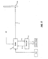
- FIG. 5 is a functional diagram of a 320 MW thermal power station, designed to be fuelled with natural gas only, without air pre heating and with boiler exit gases at 120°C.
- the mass and energy balance in principle provides the same natural gas consumption as in the previous example.
- FIG. 6 is a block diagram of the two integrated processes.
- the natural gas consumption falls from 75000 Nm 3 /h to 65000 Nm 3 /h with a saving of about 10000 Nm 3 /h, equal to approx. 13% of the value of the thermal power station operating alone.
- Specific energy production is therefore 1.6 kW/kg of secondary fuel, as against 1.08 kW/kg in the case of a stand alone waste to energy plant.
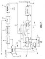
- FIG. 7 is a functional diagram of a SF combustion plant able to burn 26 t/h, with production of approx. 500 t/h of burnt gases cleaned at the temperature of 430°C, with a 14% oxygen concentration, combined to a thermal power station as described in example 1.
- Part of said burnt gas can be added via mixer 9 to line 10 of the preheated combustion air originating from gas/gas exchanger 7 to increase the temperature and reduce the oxygen content at the burners without unbalancing the performance of the boiler.
- the remainder of the burnt gas is sent directly to gas/gas exchanger 7 .
- the surplus preheated air in said exchanger approx. 235 t/h, can be used for further preheating of the recirculation water in a suitable exchanger 25 , and subsequently conveyed to the stack together with the burnt gases.
- the method and plant according to the invention solve the problem of dispersed energy due to the surplus air required by combustion of secondary fuels, as this air is subsequently used as combustion air for fossil fuels in which this surplus is not required.
- gas cleaning performed by the method and with the plant according to the invention does not produce residues containing organic material, including the dangerous aromatic polycondensates and dioxins, which are difficult and expensive to dispose of, but inorganic ash identical to that produced by perfect combustion plants.
- Elimination of all the compounds containing chlorine and other low-melting salts before entering the power station boiler allows the use of the temperatures commonly employed in thermal power stations, which are much higher than those used in incinerators, which are limited by problems of corrosion, and therefore allows the use of high-yield heat cycles.
- a further advantage is that it is unnecessary to obtain new sites for waste incinerators; the invention solves the problem of locating such plants, which can be replaced by relatively small auxiliary plants located on the site of existing thermal power stations.
- secondary fuel consists of materials classified as renewable for energy purposes, thermal power stations which can produce at least 4% of their energy with such sources are classed as users of renewable sources, and authorized to issue the corresponding certificate.
Landscapes
- Engineering & Computer Science (AREA)
- Chemical & Material Sciences (AREA)
- General Engineering & Computer Science (AREA)
- Mechanical Engineering (AREA)
- Environmental & Geological Engineering (AREA)
- General Chemical & Material Sciences (AREA)
- Life Sciences & Earth Sciences (AREA)
- Chemical Kinetics & Catalysis (AREA)
- Biochemistry (AREA)
- Combustion & Propulsion (AREA)
- Incineration Of Waste (AREA)
- Processing Of Solid Wastes (AREA)
- Gasification And Melting Of Waste (AREA)
Claims (19)
- Procédé d'exploitation des déchets, en particulier de déchets solides, dans une centrale thermique (100) dans laquelle l'énergie primaire est fournie par la combustion de combustibles fossiles avec introduction d'air de combustion, lequel dit procédé comprend la combustion (a) des déchets avec un flux d'air adéquatement régulé de telle sorte que la combustion soit approximativement complète, le refroidissement (b) des gaz brûlés au moyen d'au moins le mélange partiel à de l'air froid à une température prédéterminée (Tw) qui est inférieure à la température maximale compatible avec l'épuration des gaz, l'épuration (c) des gaz brûlés refroidis et le mélange desdits gaz brûlés épurés et refroidis avec l'air de combustion utilisé dans la centrale de manière à transférer une partie de l'énergie thermique générée par la combustion des déchets vers ledit air de combustion.
- Procédé selon la revendication 1, caractérisé en ce que la combustion (a) des déchets se fait sans un excès d'air ou avec un excès d'air prédéterminé.
- Procédé selon la revendication 2, caractérisé en ce que ledit surplus d'air prédéterminé se situe dans une fourchette approximativement comprise entre 0 à 60% de la valeur stoechiométrique.
- Procédé selon la revendication 1, caractérisé en ce que ladite épuration (c) du gaz brûlé est réalisée par filtration.
- Procédé selon la revendication 1, caractérisé en ce que les gaz brûlés épurés et refroidis sont mélangés à l'air de combustion utilisé dans la centrale de manière à remplacer au moins en partie le recyclage des gaz de combustion brûlés dans la centrale afin de réduire le NOx.
- Procédé selon la revendication 1, caractérisé en ce que ladite étape d'épuration des gaz brûlés (c) est réalisée jusqu'à ce que la teneur en poudres, composés acides inorganiques, composés aromatiques polycycliques condensés et composés organiques chlorés se situe en dessous de valeurs seuil prédéterminées.
- Procédé selon la revendication 1, caractérisé en ce qu'il comprend le refroidissement (e) du lit de combustion des déchets au moyen d'un liquide réfrigérant, au moins une partie de l'énergie thermique dudit liquide réfrigérant étant transférée (f) vers le circuit de préchauffage du liquide de la centrale de telle sorte que, pour l'essentiel, toute l'énergie obtenue à partir de la combustion des déchets soit transférée vers la centrale.
- Procédé selon la revendication 1, caractérisé en ce que les déchets sont soumis à un traitement préliminaire (g) avant la combustion de manière à fabriquer un combustible secondaire (CS).
- Procédé selon la revendication 8, caractérisé en ce que le prétraitement (g) dudit combustible secondaire (CS) comprend une étape de fermentation aérobie forcée des déchets.
- Procédé selon la revendication 8, caractérisé en ce que le prétraitement (g) dudit combustible secondaire (CS) comprend au moins une étape d'extraction des métaux et/ou des agrégats à partir des déchets.
- Procédé selon la revendication 8, caractérisé en ce que, après la fabrication, ledit combustible secondaire (CS) présente une teneur en humidité inférieure à 20% en poids, une valeur calorifique nette dépassant 17000 kJ/kg (4000 kcal/kg) et un nombre de bactéries inférieur à 1000 N/g.
- Installation d'exploitation des déchets dans une centrale thermique (100) qui met en oeuvre le procédé revendiqué dans l'une quelconque ou plusieurs des revendications précédentes, dans laquelle ladite centrale (100) est équipée d'une chambre à combustion primaire (2) pour combustibles fossiles et d'un circuit qui amène l'air de combustion vers ladite chambre de combustion (2) à une température prédéterminée (Tc), qui comprend :- des moyens de préparation des déchets pour la combustion,- des moyens (17) de combustion des déchets en présence d'un flux d'air régulé conçu pour effectuer la combustion approximativement complète des déchets,- des moyens (20) de refroidissement des gaz brûlés à une température (Tw) inférieure à la température maximale compatible avec les moyens d'épuration desdits gaz brûlés refroidis,- des moyens (21) d'épuration desdits gaz brûlés refroidis,- des moyens (9) de mélange desdits gaz brûlés épurés et refroidis à l'air de combustion utilisé dans la centrale de manière à transférer son énergie thermique, générée par la combustion des déchets, vers ledit air de combustion.
- Installation d'exploitation des déchets selon la revendication 12, caractérisée en ce que lesdits moyens de combustion des déchets (17) comprennent au moins un réacteur à combustion avec lit fluidisé équipé d'un circuit de refroidissement qui emploie un liquide réfrigérant.
- Installation d'exploitation des déchets selon la revendication 13, caractérisée en ce que le liquide réfrigérant dudit circuit de refroidissement constitue le liquide primaire d'un échangeur thermique (24) conçu pour préchauffer le recyclage du liquide vers la chaudière de la centrale de manière à transférer pour l'essentiel toute l'énergie, obtenue à partir de la combustion des déchets, vers la centrale (100).
- Installation selon la revendication 13, caractérisée en ce qu'elle comprend des moyens d'amenée de l'air vers ledit réacteur à combustion avec lit fluidisé, lesquels dits moyens peuvent être réglés de manière à moduler l'excès d'air dans une fourchette approximativement comprise entre 0 et 60% de la valeur stoechiométrique.
- Installation selon la revendication 12, caractérisée en ce que lesdits moyens (9) de mélange des gaz brûlés épurés et refroidis à l'air de combustion utilisé dans la chambre à combustion principale de la centrale sont conçus pour remplacer, au moins en partie, le recyclage des gaz de combustion dans le but de réduire le NOx.
- Installation selon la revendication 12, caractérisée en ce que lesdits moyens d'épuration (21) comprennent des moyens de filtration.
- Installation selon la revendication 12, caractérisée en ce que lesdits moyens de préparation des déchets comprennent des moyens de fabrication d'un combustible secondaire (CS) à partir desdits déchets.
- Installation selon la revendication 17, caractérisée en ce que lesdits moyens de préparation dudit carburant secondaire comprennent une installation de fermentation aérobie forcée desdits déchets.
Applications Claiming Priority (2)
| Application Number | Priority Date | Filing Date | Title |
|---|---|---|---|
| IT2002VI000160A ITVI20020160A1 (it) | 2002-07-16 | 2002-07-16 | Metodo ed impianto per l'utilizzo di rifiuti, in particolare rifiuti solidi urbani, in una centrale termoelettrica di potenza |
| ITVI20020160 | 2002-07-16 |
Publications (3)
| Publication Number | Publication Date |
|---|---|
| EP1382806A2 EP1382806A2 (fr) | 2004-01-21 |
| EP1382806A3 EP1382806A3 (fr) | 2004-06-30 |
| EP1382806B1 true EP1382806B1 (fr) | 2007-11-28 |
Family
ID=29766145
Family Applications (1)
| Application Number | Title | Priority Date | Filing Date |
|---|---|---|---|
| EP03009305A Expired - Lifetime EP1382806B1 (fr) | 2002-07-16 | 2003-04-24 | Procédé et installation pour utiliser des déchets dans une centrale thermoelectrique |
Country Status (3)
| Country | Link |
|---|---|
| EP (1) | EP1382806B1 (fr) |
| DE (1) | DE60317740D1 (fr) |
| IT (1) | ITVI20020160A1 (fr) |
Families Citing this family (2)
| Publication number | Priority date | Publication date | Assignee | Title |
|---|---|---|---|---|
| CN104312918B (zh) * | 2014-10-23 | 2016-06-15 | 湖南屎壳郎环境科技有限公司 | 一种利用燃烧废气促进好氧发酵反应的方法 |
| US9875503B2 (en) | 2015-03-06 | 2018-01-23 | Wal-Mart Stores, Inc. | Method and apparatus for transporting a plurality of stacked motorized transport units |
Family Cites Families (6)
| Publication number | Priority date | Publication date | Assignee | Title |
|---|---|---|---|---|
| AT390304B (de) * | 1987-04-14 | 1990-04-25 | Sonnek Rudolf Ing | Verfahren zur verwendung von muell als brennstoff fuer umweltfreundliche energienutzung |
| DE4006288A1 (de) * | 1989-03-23 | 1990-09-27 | Pauli Balduin | Verfahren und vorrichtung zum behandeln der rauchgase aus sondermuell- und klinikmuellverbrennungsanlagen |
| ATA121889A (de) * | 1989-05-22 | 1995-02-15 | Sonnek Rudolf Ing | Verfahren zur verwendung von müll als brennstoff für umweltfreundliche stromerzeugung |
| DE4442136C2 (de) * | 1994-11-26 | 1997-10-02 | Hoelter Heinz | Verfahren zur Verbrennung von fossilem Brennstoff und Abfall |
| JP4122546B2 (ja) * | 1997-08-27 | 2008-07-23 | 大同特殊鋼株式会社 | 高温炉の操業方法 |
| JP3623705B2 (ja) * | 1999-12-16 | 2005-02-23 | 株式会社プランテック | ごみ焼却施設におけるダイオキシン類の除去設備及びその除去方法 |
-
2002
- 2002-07-16 IT IT2002VI000160A patent/ITVI20020160A1/it unknown
-
2003
- 2003-04-24 EP EP03009305A patent/EP1382806B1/fr not_active Expired - Lifetime
- 2003-04-24 DE DE60317740T patent/DE60317740D1/de not_active Expired - Lifetime
Also Published As
| Publication number | Publication date |
|---|---|
| EP1382806A2 (fr) | 2004-01-21 |
| EP1382806A3 (fr) | 2004-06-30 |
| DE60317740D1 (de) | 2008-01-10 |
| ITVI20020160A1 (it) | 2004-01-16 |
Similar Documents
| Publication | Publication Date | Title |
|---|---|---|
| Morris et al. | Energy recovery from solid waste fuels using advanced gasification technology | |
| Lecomte et al. | Best available techniques (BAT) reference document for large combustion plants. Industrial emissions directive 2010/75/EU (Integrated pollution prevention and control) | |
| US5000099A (en) | Combination of fuels conversion and pressurized wet combustion | |
| CN103934254B (zh) | 一种水泥窑协同处理城市生活垃圾的系统及方法 | |
| CN112062435B (zh) | 一种油泥热解处理装置及其工艺 | |
| CN105066135A (zh) | 一种小型垃圾气化催化裂解的工艺方法及其设备 | |
| CN112779057A (zh) | 一种油泥综合处理系统及油泥综合处理方法 | |
| JP4081102B2 (ja) | 廃棄物複合処理施設 | |
| JP4652609B2 (ja) | 石炭燃焼灰の溶融方法および溶融処理システム | |
| CN105602600A (zh) | 一种餐厨垃圾热解制油节能处理系统 | |
| EP1382806A2 (fr) | Procédé et installation pour utiliser des déchets dans une centrale thermoelectrique | |
| KR101482574B1 (ko) | 화력발전 연계형 가스화 시스템 | |
| CN217763445U (zh) | 一种工业固废及污泥处置系统 | |
| JP2000283434A (ja) | 廃棄物処理方法及び廃棄物処理システム | |
| Bawkon | Incineration technologies for managing solid waste | |
| EP1416223B1 (fr) | Procédé et installation pour l'utilisation d'energie de déchets en centrale combiné ayant un effet faible pour l'environnement | |
| JP2740644B2 (ja) | 灰の溶融装置およびその方法 | |
| EP1428987B1 (fr) | Méthode et installation permettant d'améliorer la consommation de carburant fossile dans les centrales électriques conventionnelles | |
| JP2000283435A (ja) | 廃棄物処理方法及び廃棄物処理システム | |
| Mahi | Environmental assessment of combined heat and power projects | |
| Arena et al. | Pyrolysis and gasification of solid wastes in fluidized bed reactors | |
| JP4089080B2 (ja) | 廃棄物処理方法及び廃棄物処理システム | |
| EP1479455B1 (fr) | Centrale et procédé combinés pour obtenir de l'énergie électrique a partir de déchets domestiques | |
| JP2007002825A (ja) | 廃棄物発電方法 | |
| JP2001050010A (ja) | 発電設備 |
Legal Events
| Date | Code | Title | Description |
|---|---|---|---|
| PUAI | Public reference made under article 153(3) epc to a published international application that has entered the european phase |
Free format text: ORIGINAL CODE: 0009012 |
|
| AK | Designated contracting states |
Kind code of ref document: A2 Designated state(s): AT BE BG CH CY CZ DE DK EE ES FI FR GB GR HU IE IT LI LU MC NL PT RO SE SI SK TR |
|
| AX | Request for extension of the european patent |
Extension state: AL LT LV MK |
|
| PUAL | Search report despatched |
Free format text: ORIGINAL CODE: 0009013 |
|
| AK | Designated contracting states |
Kind code of ref document: A3 Designated state(s): AT BE BG CH CY CZ DE DK EE ES FI FR GB GR HU IE IT LI LU MC NL PT RO SE SI SK TR |
|
| AX | Request for extension of the european patent |
Extension state: AL LT LV MK |
|
| RIC1 | Information provided on ipc code assigned before grant |
Ipc: 7B 09B 3/00 B Ipc: 7F 23G 5/00 B Ipc: 7F 23G 5/02 B Ipc: 7F 01K 3/24 A |
|
| 17P | Request for examination filed |
Effective date: 20041210 |
|
| AKX | Designation fees paid |
Designated state(s): AT BE BG CH CY CZ DE DK EE ES FI FR GB GR HU IE IT LI LU MC NL PT RO SE SI SK TR |
|
| AXX | Extension fees paid |
Extension state: MK Payment date: 20041210 Extension state: AL Payment date: 20041210 Extension state: LT Payment date: 20041210 Extension state: LV Payment date: 20041210 |
|
| GRAP | Despatch of communication of intention to grant a patent |
Free format text: ORIGINAL CODE: EPIDOSNIGR1 |
|
| GRAS | Grant fee paid |
Free format text: ORIGINAL CODE: EPIDOSNIGR3 |
|
| GRAA | (expected) grant |
Free format text: ORIGINAL CODE: 0009210 |
|
| AK | Designated contracting states |
Kind code of ref document: B1 Designated state(s): AT BE BG CH CY CZ DE DK EE ES FI FR GB GR HU IE IT LI LU MC NL PT RO SE SI SK TR |
|
| AX | Request for extension of the european patent |
Extension state: AL LT LV MK |
|
| REG | Reference to a national code |
Ref country code: IE Ref legal event code: FG4D |
|
| REG | Reference to a national code |
Ref country code: CH Ref legal event code: EP |
|
| REF | Corresponds to: |
Ref document number: 60317740 Country of ref document: DE Date of ref document: 20080110 Kind code of ref document: P |
|
| PG25 | Lapsed in a contracting state [announced via postgrant information from national office to epo] |
Ref country code: ES Free format text: LAPSE BECAUSE OF FAILURE TO SUBMIT A TRANSLATION OF THE DESCRIPTION OR TO PAY THE FEE WITHIN THE PRESCRIBED TIME-LIMIT Effective date: 20080311 Ref country code: SE Free format text: LAPSE BECAUSE OF FAILURE TO SUBMIT A TRANSLATION OF THE DESCRIPTION OR TO PAY THE FEE WITHIN THE PRESCRIBED TIME-LIMIT Effective date: 20080228 Ref country code: NL Free format text: LAPSE BECAUSE OF FAILURE TO SUBMIT A TRANSLATION OF THE DESCRIPTION OR TO PAY THE FEE WITHIN THE PRESCRIBED TIME-LIMIT Effective date: 20071128 Ref country code: LI Free format text: LAPSE BECAUSE OF FAILURE TO SUBMIT A TRANSLATION OF THE DESCRIPTION OR TO PAY THE FEE WITHIN THE PRESCRIBED TIME-LIMIT Effective date: 20071128 Ref country code: CH Free format text: LAPSE BECAUSE OF FAILURE TO SUBMIT A TRANSLATION OF THE DESCRIPTION OR TO PAY THE FEE WITHIN THE PRESCRIBED TIME-LIMIT Effective date: 20071128 |
|
| NLV1 | Nl: lapsed or annulled due to failure to fulfill the requirements of art. 29p and 29m of the patents act | ||
| LTIE | Lt: invalidation of european patent or patent extension |
Effective date: 20071128 |
|
| PG25 | Lapsed in a contracting state [announced via postgrant information from national office to epo] |
Ref country code: BG Free format text: LAPSE BECAUSE OF FAILURE TO SUBMIT A TRANSLATION OF THE DESCRIPTION OR TO PAY THE FEE WITHIN THE PRESCRIBED TIME-LIMIT Effective date: 20080228 Ref country code: FI Free format text: LAPSE BECAUSE OF FAILURE TO SUBMIT A TRANSLATION OF THE DESCRIPTION OR TO PAY THE FEE WITHIN THE PRESCRIBED TIME-LIMIT Effective date: 20071128 Ref country code: SI Free format text: LAPSE BECAUSE OF FAILURE TO SUBMIT A TRANSLATION OF THE DESCRIPTION OR TO PAY THE FEE WITHIN THE PRESCRIBED TIME-LIMIT Effective date: 20071128 |
|
| REG | Reference to a national code |
Ref country code: CH Ref legal event code: PL |
|
| PG25 | Lapsed in a contracting state [announced via postgrant information from national office to epo] |
Ref country code: AT Free format text: LAPSE BECAUSE OF FAILURE TO SUBMIT A TRANSLATION OF THE DESCRIPTION OR TO PAY THE FEE WITHIN THE PRESCRIBED TIME-LIMIT Effective date: 20071128 |
|
| PG25 | Lapsed in a contracting state [announced via postgrant information from national office to epo] |
Ref country code: CZ Free format text: LAPSE BECAUSE OF FAILURE TO SUBMIT A TRANSLATION OF THE DESCRIPTION OR TO PAY THE FEE WITHIN THE PRESCRIBED TIME-LIMIT Effective date: 20071128 Ref country code: DK Free format text: LAPSE BECAUSE OF FAILURE TO SUBMIT A TRANSLATION OF THE DESCRIPTION OR TO PAY THE FEE WITHIN THE PRESCRIBED TIME-LIMIT Effective date: 20071128 |
|
| PG25 | Lapsed in a contracting state [announced via postgrant information from national office to epo] |
Ref country code: BE Free format text: LAPSE BECAUSE OF FAILURE TO SUBMIT A TRANSLATION OF THE DESCRIPTION OR TO PAY THE FEE WITHIN THE PRESCRIBED TIME-LIMIT Effective date: 20071128 Ref country code: SK Free format text: LAPSE BECAUSE OF FAILURE TO SUBMIT A TRANSLATION OF THE DESCRIPTION OR TO PAY THE FEE WITHIN THE PRESCRIBED TIME-LIMIT Effective date: 20071128 Ref country code: RO Free format text: LAPSE BECAUSE OF FAILURE TO SUBMIT A TRANSLATION OF THE DESCRIPTION OR TO PAY THE FEE WITHIN THE PRESCRIBED TIME-LIMIT Effective date: 20071128 |
|
| EN | Fr: translation not filed | ||
| PG25 | Lapsed in a contracting state [announced via postgrant information from national office to epo] |
Ref country code: PT Free format text: LAPSE BECAUSE OF FAILURE TO SUBMIT A TRANSLATION OF THE DESCRIPTION OR TO PAY THE FEE WITHIN THE PRESCRIBED TIME-LIMIT Effective date: 20080428 |
|
| PLBE | No opposition filed within time limit |
Free format text: ORIGINAL CODE: 0009261 |
|
| STAA | Information on the status of an ep patent application or granted ep patent |
Free format text: STATUS: NO OPPOSITION FILED WITHIN TIME LIMIT |
|
| PG25 | Lapsed in a contracting state [announced via postgrant information from national office to epo] |
Ref country code: DE Free format text: LAPSE BECAUSE OF FAILURE TO SUBMIT A TRANSLATION OF THE DESCRIPTION OR TO PAY THE FEE WITHIN THE PRESCRIBED TIME-LIMIT Effective date: 20080229 Ref country code: FR Free format text: LAPSE BECAUSE OF FAILURE TO SUBMIT A TRANSLATION OF THE DESCRIPTION OR TO PAY THE FEE WITHIN THE PRESCRIBED TIME-LIMIT Effective date: 20080912 |
|
| 26N | No opposition filed |
Effective date: 20080829 |
|
| PG25 | Lapsed in a contracting state [announced via postgrant information from national office to epo] |
Ref country code: MC Free format text: LAPSE BECAUSE OF NON-PAYMENT OF DUE FEES Effective date: 20080430 |
|
| GBPC | Gb: european patent ceased through non-payment of renewal fee |
Effective date: 20080424 |
|
| PG25 | Lapsed in a contracting state [announced via postgrant information from national office to epo] |
Ref country code: EE Free format text: LAPSE BECAUSE OF FAILURE TO SUBMIT A TRANSLATION OF THE DESCRIPTION OR TO PAY THE FEE WITHIN THE PRESCRIBED TIME-LIMIT Effective date: 20071128 Ref country code: GR Free format text: LAPSE BECAUSE OF FAILURE TO SUBMIT A TRANSLATION OF THE DESCRIPTION OR TO PAY THE FEE WITHIN THE PRESCRIBED TIME-LIMIT Effective date: 20080229 |
|
| PG25 | Lapsed in a contracting state [announced via postgrant information from national office to epo] |
Ref country code: IE Free format text: LAPSE BECAUSE OF NON-PAYMENT OF DUE FEES Effective date: 20080424 |
|
| PG25 | Lapsed in a contracting state [announced via postgrant information from national office to epo] |
Ref country code: GB Free format text: LAPSE BECAUSE OF NON-PAYMENT OF DUE FEES Effective date: 20080424 |
|
| PG25 | Lapsed in a contracting state [announced via postgrant information from national office to epo] |
Ref country code: CY Free format text: LAPSE BECAUSE OF FAILURE TO SUBMIT A TRANSLATION OF THE DESCRIPTION OR TO PAY THE FEE WITHIN THE PRESCRIBED TIME-LIMIT Effective date: 20071128 |
|
| PG25 | Lapsed in a contracting state [announced via postgrant information from national office to epo] |
Ref country code: LU Free format text: LAPSE BECAUSE OF NON-PAYMENT OF DUE FEES Effective date: 20080424 Ref country code: HU Free format text: LAPSE BECAUSE OF FAILURE TO SUBMIT A TRANSLATION OF THE DESCRIPTION OR TO PAY THE FEE WITHIN THE PRESCRIBED TIME-LIMIT Effective date: 20080529 |
|
| PG25 | Lapsed in a contracting state [announced via postgrant information from national office to epo] |
Ref country code: TR Free format text: LAPSE BECAUSE OF FAILURE TO SUBMIT A TRANSLATION OF THE DESCRIPTION OR TO PAY THE FEE WITHIN THE PRESCRIBED TIME-LIMIT Effective date: 20071128 |
|
| PG25 | Lapsed in a contracting state [announced via postgrant information from national office to epo] |
Ref country code: IT Free format text: LAPSE BECAUSE OF NON-PAYMENT OF DUE FEES Effective date: 20080430 |