EP1382849A2 - Elektrischer Kompressor - Google Patents
Elektrischer Kompressor Download PDFInfo
- Publication number
- EP1382849A2 EP1382849A2 EP03015985A EP03015985A EP1382849A2 EP 1382849 A2 EP1382849 A2 EP 1382849A2 EP 03015985 A EP03015985 A EP 03015985A EP 03015985 A EP03015985 A EP 03015985A EP 1382849 A2 EP1382849 A2 EP 1382849A2
- Authority
- EP
- European Patent Office
- Prior art keywords
- drive circuit
- electrical components
- accommodating space
- motor drive
- central axis
- Prior art date
- Legal status (The legal status is an assumption and is not a legal conclusion. Google has not performed a legal analysis and makes no representation as to the accuracy of the status listed.)
- Granted
Links
Images


Classifications
-
- F—MECHANICAL ENGINEERING; LIGHTING; HEATING; WEAPONS; BLASTING
- F04—POSITIVE - DISPLACEMENT MACHINES FOR LIQUIDS; PUMPS FOR LIQUIDS OR ELASTIC FLUIDS
- F04C—ROTARY-PISTON, OR OSCILLATING-PISTON, POSITIVE-DISPLACEMENT MACHINES FOR LIQUIDS; ROTARY-PISTON, OR OSCILLATING-PISTON, POSITIVE-DISPLACEMENT PUMPS
- F04C23/00—Combinations of two or more pumps, each being of rotary-piston or oscillating-piston type, specially adapted for elastic fluids; Pumping installations specially adapted for elastic fluids; Multi-stage pumps specially adapted for elastic fluids
- F04C23/008—Hermetic pumps
-
- F—MECHANICAL ENGINEERING; LIGHTING; HEATING; WEAPONS; BLASTING
- F04—POSITIVE - DISPLACEMENT MACHINES FOR LIQUIDS; PUMPS FOR LIQUIDS OR ELASTIC FLUIDS
- F04B—POSITIVE-DISPLACEMENT MACHINES FOR LIQUIDS; PUMPS
- F04B35/00—Piston pumps specially adapted for elastic fluids and characterised by the driving means to their working members, or by combination with, or adaptation to, specific driving engines or motors, not otherwise provided for
- F04B35/04—Piston pumps specially adapted for elastic fluids and characterised by the driving means to their working members, or by combination with, or adaptation to, specific driving engines or motors, not otherwise provided for the means being electric
Definitions
- the present invention relates to an electric compressor including a compression mechanism that is driven by an electric motor.
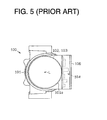
- FIG. 5 a diagram illustrates a front end view of a motor compressor or an electric compressor 100 according to a prior art.
- a compressor housing 101 forms an outer shell of the motor compressor 100.
- An electric motor 102 and a compression mechanism 103 are accommodated in the compressor housing 101.
- the compressor housing 101 includes a substantially cylindrical circumferential wall 101 a around a central axis L of the motor compressor 100, and a motor drive circuit 104 is arranged on the circumferential wall 101a.
- the motor drive circuit 104 includes an inverter and the like for driving the electric motor 102.
- the motor drive circuit 104 mounted on the circumferential wall 101a in a state where the motor drive circuit 104 is accommodated in a casing 106.
- the circumferential wall 101 a forms substantially cylindrical in shape, while the casing 106 forms cubic in shape. Since the circumferential wall 101a is different in shape than the casing 106, the casing 106 largely protrudes from the compressor housing 101 in the transverse direction. Accordingly, the motor compressor 100 becomes undesirably large in size. Therefore, there is a need for an electric compressor that reduces the number of components and that efficiently becomes compact.
- an electric compressor has a compressor housing, a compression mechanism, an electric motor, an accommodating portion and a motor drive circuit.
- the compressor housing has a circumferential wall and a central axis.
- the compression mechanism is arranged in the compressor housing for compressing fluid.
- the electric motor is operatively connected to the compression mechanism for driving the compression mechanism.
- the accommodating portion is provided on an outer surface of the compressor housing and defines an accommodating space.
- the inner surface of the accommodating space includes a bottom surface and a side surface.
- the bottom surface is defined as a radially inward surface of the inner surface relative to the central axis.
- the side surface surrounds a periphery of the bottom surface. the bottom and side surfaces are defined by the compressor housing.
- the motor drive circuit is arranged in the accommodating space for driving the electric motor.
- FIG. 1 a diagram illustrates a longitudinal cross-sectional view of a motor compressor or an electric compressor 10 according to the preferred embodiment of the present invention.
- a compressor housing 11 forms an outer shell of the motor compressor 10 and includes a first housing element 21 and a second housing element 22.
- the first housing element 21 has a substantially cylindrical circumferential wall 23 and an end wall that is formed on the left end of the circumferential wall 23 in the drawing.
- the first housing element 21 is die-cast in an aluminum alloy.
- the second housing element 22 forms a cylinder with an end wall on the right end in the drawing and is die-cast in an aluminum alloy.
- the first and second housing elements 21, 22 are fixedly connected with each other so that a closed space 24 is defined in the compressor housing 11.
- a rotary shaft 27 is rotatably supported by the first housing element 21 in the closed space 24 and has a central axis of rotation that is identical to the central axis L of the motor compressor 10.
- the circumferential wall 23 of the first housing element 21 surrounds the central axis L of the motor compressor 10.
- the electric motor 25 is a brushless direct current type or a brushless DC type and includes a stator 25a and a rotor 25b.
- the stator 25a is fixedly connected to an inner surface 23a of the circumferential wall 23 of the first housing element 21.
- the rotor 25b is provided on the rotary shaft 27 and is arranged inside the stator 25a.
- the electric motor 25 rotates the rotary shaft by electric power that is supplied to the stator 25a.
- the compression mechanism 26 is a scroll type and includes a fixed scroll member 26a and a movable scroll member 26b. As the movable scroll member 26b orbits relative to the fixed scroll member 26a in accordance with the rotation of the rotary shaft 27, the compression mechanism 26 compresses refrigerant gas or fluid. An outlet 32 is formed in the second housing element 22 for discharging the compressed refrigerant gas to an external refrigerant circuit, which is not shown in the drawing.
- the refrigerant gas in relatively low temperature and relatively low pressure is introduced from the external refrigerant circuit into the compression mechanism 26 through the electric motor 25.
- the introduced refrigerant gas is compressed to have relatively high temperature and relatively high pressure by the compression mechanism 26.
- the refrigerant gas is discharged to the external refrigerant circuit through the outlet 32.
- the refrigerant gas in relatively low temperature from the external refrigerant circuit cools the electric motor 25 as it passes by the electric motor 25.
- FIG. 2 a diagram illustrates a side view of the motor compressor 10 according to the preferred embodiment of the present invention.
- An inlet 31 is formed in the first housing element 21.
- the refrigerant gas is introduced from the external refrigerant circuit into the compressor housing 11 through the inlet 31.
- FIG. 3 a diagram illustrates a partially enlarged cross-sectional view that is taken along the line I-I in FIG. 2.
- An outer surface 23b of the circumferential wall 23 is mostly formed along a cylindrical surface R having the central axis L.
- the first housing element 21 partially includes an accommodating portion 36.
- the accommodating portion 36 is provided on a portion of the outer surface 23b of the circumferential wall 23 and defines an accommodating space 35 inside.
- the accommodating portion 36 includes a frame-shaped side wall 37 and a cover member 38.
- the side wall 37 is integrally formed with the circumferential wall 23 and extends from the outer surface 23b.
- the cover member 38 is fixedly connected to the distal end surface of the side wall 37 by a fixing frame 40.
- the cover member 38 covers the opening of the side wall 37.
- the cover member 38 forms a thin plate and is made of metal such as an aluminum alloy.
- a seal member 39 is interposed between the distal end surface of the side wall 37 and the outer peripheral portion of the cover member 38 for sealing the accommodating space 35.
- the outer surface 23b of the circumferential wall 23 defines a bottom surface 35a of the accommodating space 35.
- the bottom surface 35a corresponds to a surface on the near side relative to the central axis L, that is, a radially inward surface of the compressor housing 11 relative to the central axis L, among inner surfaces of the accommodating space 35.
- the inner surface of the side wall 37 substantially defines a side surface 35b of the accommodating space 35.
- the first housing element 21 substantially defines the bottom and side surfaces 35a, 35b of the accommodating space 35. That is, the inner surface of the accommodating space 35 includes the bottom and side surfaces 35a, 35b.
- the side surface 35b surrounds the periphery of the bottom surface 35a.
- the cover member 38 defines a top surface 35c of the accommodating space 35. In other words, the top surface 35c is formed by the cover member 38.
- the side wall 37 does not completely surround the side of a motor drive circuit 41.
- the motor drive circuit 41 is accommodated in the accommodating space 35 in the accommodating portion 36 for driving the electric motor 25.
- the motor drive circuit 41 includes an inverter and supplies the stator 25a of the electric motor 25 with electric power based on a command from an air conditioner ECU, which is not shown in the drawing.
- the refrigerant gas cools the motor drive circuit 41 as it is introduced from the external refrigerant circuit to the compression mechanism 26 through the electric motor 25.
- the motor drive circuit 41 includes a planar substrate 43 and a plurality of electrical components 44.
- the substrate 43 is fixedly connected to the circumferential wall 23 by a fastener, such as a bolt, which is not shown in the drawing.
- the substrate 43 is substantially in parallel with the central axis L of the motor compressor 10.
- the electrical components 44 are respectively mounted on surfaces 43a, 43b of the substrate 43. Namely, the electrical components 44 are respectively mounted on the substrate 43 on the near and far sides relative to the central axis L.
- the electrical components 44 include electrical components 44A through 44E and other electrical components, which are not shown in the drawing.
- the electrical components 44 include known components for constituting the inverter. That is, the electrical components 44 include a switching device 44A, an electrolytic condenser 44B, a transformer 44C, a driver 44D, a fixed resistance and the like.
- the driver 44D is an integrated circuit chip or an IC chip for intermittently controlling the switching device 44A based on a command from the air conditioner ECU.
- the switching device 44A has a height of h3 from the substrate 43 and is mounted on the surface 43a of the substrate 43, that is, on the substrate 43 on the near side relative to the central axis L. Some of the electrical components 44 are shorter than the switching device 44A if they are mounted on the same surface. Only the above shorter electrical components 44 are mounted on the surface 43b of the substrate 43, that is, on the substrate 43 on the far side relative to the central axis L. The above shorter electrical components 44 include the driver 44D and the fixed resistance 44E.
- the taller electrical components 44 have heights of h1, h2 from the substrate 43 and are taller than the switching device 44A.
- the taller electrical components 44 and the switching device 44A are mounted on the surface 43a of the substrate 43, that is, on the substrate 43 on the near side relative to the central axis L.
- the taller electrical components 44 include the electrolytic condenser 44B and the transformer 44C. Accordingly, among the electrical components 44 on the surface 43a of the substrate 43, the switching device 44A corresponds to a short electrical component that has a relatively short height of h3 from the substrate 43, and the electrolytic condenser 44B and the transformer 44C correspond to tall electrical components that have relatively tall heights of h1, h2.
- the electrical components 44 on the surface 43a are arranged as follows.
- the short electrical components such as the switching device 44A are arranged at the middle portion of the surface 43a of the substrate 43.
- the tall electrical components such as the electrolytic condenser 44B and the transformer 44C are arranged at both ends of the surface 43a, that is, the upper and lower ends of the surface 43a in FIG. 3. Namely, the short electrical components are arranged relatively closer to the central axis L, while the tall electrical components are arranged relatively farther from the central axis L.
- the motor drive circuit 41 is installed to the compressor housing 11 in such a manner that the electrical components 44 on the surface 43a of the substrate 43 line the cylindrical surface R of the circumferential wall 23.
- the switching device 44A, the electrolytic condenser 44B and the transformer 44C each are plurally arranged in the direction of the central axis L.
- a clearance between the bottom surface 35a and the top surface 35c is relatively narrow at the middle region of the accommodating space 35 in the accommodating portion 36, and the short electrical components such as the switching device 44A are arranged at the middle region of the accommodating space 35.
- Clearances between the bottom surface 35a and the top surface 35c are relatively wide at both end regions relative to the middle region of the accommodating space 35, and the tall electrical components such as the electrolytic condenser 44B and the transformer 44C are arranged at the above end regions.
- the bottom surface 35a of the accommodating space 35 includes a convex surface at its middle where the bottom surface 35a approaches the top surface 35c to the maximum. Accordingly, in comparison to an accommodating space that includes an entire planar bottom surface, the accommodating space 35 partially forms the shape along the cylindrical surface R of the circumferential wall 23.
- the electrical components 44 are arranged on the surface 43a of the substrate 43 along the cylindrical surface R of the circumferential wall 23. Therefore, the motor drive circuit 41 is arranged to approach the central axis L of the motor compressor 10 because the electrical components 44 line the cylindrical surface R of the circumferential wall 23.
- the substrate 43 is arranged at a distance of h4 from the cylindrical surface R.
- the distance h4 is shorter than the height h1 of the electrolytic condenser 44B that is the tallest in the electrical components 44.
- the cylindrical surface R of the circumferential wall 23 approaches the surface 43a of the substrate 43 without any interference with the electrical components 44 on the surface 43a, that is, without crossing the electrical components 44 on the surface 43a.
- the motor drive circuit 41 is arranged near the central axis L of the motor compressor 10 so that the cylindrical surface R of the circumferential wall 23 is arranged at the distance h4 from the substrate 43 and the distance h4 is shorter than the height h1 of the electrolytic condenser 44B.
- the electrical components 44 line the cylindrical surface R of the circumferential wall 23 means a state where the the cylindrical surface R of the circumferential wall 23 approaches the surface 43a in such a manner that the distance h4 from the substrate 43 at least becomes shorter than the height h1 of the electrolytic condenser 44B while the cylindrical surface R of the circumferential wall 23 does not interfere with the electrical components 44 on the surface 43a.
- the cylindrical surface R of the circumferential wall 23 approaches the surface 43a of the substrate 43 in such a manner that the distance h4 from the substrate 43 becomes shorter than the height h2 of the transformer 44C, which is the second tallest, and the cylindrical surface R does not interfere with the electrical components 44 on the surface 43a. Accordingly, the electrical components 44 on the surface 43a adjacently line the cylindrical surface R of the circumferential wall 23 so that the motor drive circuit 41 is arranged near the central axis L much closer.
- the switching device 44A, the electrolytic condenser 44B and the transformer 44C are in contact with the bottom surface 35a of the accommodating space 35 through a sheet or a first insulating member 45 made of rubber or resin.
- the sheet 45 is interposed between the electrical components 44A, 44B, 44C and the first housing element 21 made of aluminum, respectively.
- a material having properties of relatively high elasticity and/or relatively high heat conductivity is employed as the sheet 45.
- a clearance between the top surface 35c of the cover member 38 and the motor drive circuit 41 is filled with a filler or a second insulating member 46 made of rubber or resin.
- the filler 46 has properties of relatively high elasticity and/or relatively high heat conductivity.
- the electrical components 44 on the surface 43a of the substrate 43 line the cylindrical surface R of the circumferential wall 23. Since the electrical components 44 line the cylindrical surface R, the motor drive circuit 41 is arranged relatively close to the central axis L of the compressor housing 11. Thus, the protrusion of the motor drive circuit 41 from the compressor housing 11 is controlled at a relatively small amount so that the motor compressor 10 becomes small in diameter.
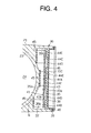
- FIG. 4 a diagram illustrates a partially enlarged cross-sectional view of a motor compressor.
- the side wall 37 extends to a higher position than the motor drive circuit 41. That is, the side wall 37 is positioned on the right side relative to the motor drive circuit 41 in the drawing.
- the side wall 37 of the compressor housing 11 having relatively high rigidity completely surrounds the side of the motor drive circuit 41 so that it effectively protects the motor drive circuit 41 against an impact from the outside.
- a motor compressor includes an electric motor and a compression mechanism that are independent to each other.
- a motor drive circuit is mounted on a compressor housing that exclusively accommodates the compression mechanism.
- an electric motor and a compression mechanism are respectively accommodated in different compressor housings in a motor compressor.
- a motor drive circuit is arranged in one of the compressor housing that accommodates the electric motor and the other that accommodates the compression mechanism.
- the motor compressor is a hybrid compressor that includes two drive sources for driving the compression mechanism 26.
- the two drive sources are an electric motor and an engine for driving a vehicle.
- the compression mechanism 26 is not limited to a scroll type.
- a piston type, a vane type and a helical type are applicable.
Landscapes
- Engineering & Computer Science (AREA)
- Mechanical Engineering (AREA)
- General Engineering & Computer Science (AREA)
- Compressor (AREA)
Applications Claiming Priority (2)
| Application Number | Priority Date | Filing Date | Title |
|---|---|---|---|
| JP2002205273 | 2002-07-15 | ||
| JP2002205273A JP3997855B2 (ja) | 2002-07-15 | 2002-07-15 | 電動コンプレッサ |
Publications (3)
| Publication Number | Publication Date |
|---|---|
| EP1382849A2 true EP1382849A2 (de) | 2004-01-21 |
| EP1382849A3 EP1382849A3 (de) | 2005-08-10 |
| EP1382849B1 EP1382849B1 (de) | 2011-09-21 |
Family
ID=29774586
Family Applications (1)
| Application Number | Title | Priority Date | Filing Date |
|---|---|---|---|
| EP03015985A Expired - Lifetime EP1382849B1 (de) | 2002-07-15 | 2003-07-14 | Elektrischer Kompressor |
Country Status (3)
| Country | Link |
|---|---|
| US (1) | US7112045B2 (de) |
| EP (1) | EP1382849B1 (de) |
| JP (1) | JP3997855B2 (de) |
Cited By (2)
| Publication number | Priority date | Publication date | Assignee | Title |
|---|---|---|---|---|
| EP2354550A3 (de) * | 2010-02-01 | 2011-10-05 | Mitsubishi Heavy Industries, Ltd. | Elektrischer Kompressor mit integriertem Umrichter |
| CN103452830A (zh) * | 2012-05-30 | 2013-12-18 | 株式会社丰田自动织机 | 马达驱动压缩机 |
Families Citing this family (14)
| Publication number | Priority date | Publication date | Assignee | Title |
|---|---|---|---|---|
| JP4718936B2 (ja) * | 2005-04-18 | 2011-07-06 | 三菱重工業株式会社 | インバータ内蔵圧縮機 |
| JP5552665B2 (ja) * | 2006-01-25 | 2014-07-16 | 株式会社豊田自動織機 | 電動コンプレッサ |
| EP1978253B1 (de) * | 2006-01-25 | 2014-09-10 | Kabushiki Kaisha Toyota Jidoshokki | Elektrischer verdichter |
| JP2008082220A (ja) * | 2006-09-27 | 2008-04-10 | Denso Corp | 電動コンプレッサ |
| JP4645602B2 (ja) * | 2006-10-04 | 2011-03-09 | トヨタ自動車株式会社 | 車両の駆動装置 |
| US8007255B2 (en) * | 2006-11-22 | 2011-08-30 | Mitsubishi Heavy Industries, Ltd. | Inverter-integrated electric compressor with inverter storage box arrangement |
| JP2009091987A (ja) * | 2007-10-09 | 2009-04-30 | Mitsubishi Heavy Ind Ltd | 車両空調用電動圧縮機 |
| JP5260198B2 (ja) * | 2008-09-08 | 2013-08-14 | 三菱重工業株式会社 | インバータ一体型電動圧縮機 |
| US8777591B2 (en) * | 2010-02-16 | 2014-07-15 | Heng Sheng Precision Tech. Co., Ltd. | Electrically driven compressor system for vehicles |
| JP5505352B2 (ja) * | 2011-03-31 | 2014-05-28 | 株式会社豊田自動織機 | 電動圧縮機 |
| JP5861614B2 (ja) * | 2012-11-12 | 2016-02-16 | 株式会社デンソー | 高電圧電気装置及び電動圧縮機 |
| DE102014114837A1 (de) * | 2014-10-13 | 2016-04-14 | Bitzer Kühlmaschinenbau Gmbh | Kältemittelverdichter |
| DE102019205757A1 (de) * | 2019-04-23 | 2020-10-29 | Zf Friedrichshafen Ag | Getriebeanordnung für ein Kraftfahrzeug und Verfahren zur Montage einer Getriebeanordnung |
| JPWO2021044853A1 (de) * | 2019-09-03 | 2021-03-11 |
Family Cites Families (15)
| Publication number | Priority date | Publication date | Assignee | Title |
|---|---|---|---|---|
| JPH0653500B2 (ja) | 1985-07-11 | 1994-07-20 | マツダ株式会社 | 車両の4輪操舵装置 |
| JPS6219535A (ja) | 1985-07-17 | 1987-01-28 | Taisho Pharmaceut Co Ltd | リゾチ−ムシロツプ剤 |
| JP3086819B2 (ja) | 1990-07-20 | 2000-09-11 | セイコーエプソン株式会社 | 空気調和機用モータ一体型圧縮機 |
| DE4038394A1 (de) * | 1990-12-01 | 1992-06-04 | Bosch Gmbh Robert | Anordnung zur dichten durchfuehrung eines leiters durch die wand eines gehaeuses |
| DE4418271A1 (de) * | 1994-05-26 | 1995-11-30 | Voith Gmbh J M | Antriebseinheit |
| DK172128B1 (da) | 1995-07-06 | 1997-11-17 | Danfoss As | Kompressor med styreelektronik |
| GB9626298D0 (en) * | 1996-12-19 | 1997-02-05 | Lucas Ind Plc | Improvements relating to powder-assisted steering assemblies |
| US5904471A (en) | 1996-12-20 | 1999-05-18 | Turbodyne Systems, Inc. | Cooling means for a motor-driven centrifugal air compressor |
| DE19817333C5 (de) * | 1998-04-18 | 2007-04-26 | Conti Temic Microelectronic Gmbh | Elektrische Antriebseinheit aus Elektromotor und Elektronikmodul |
| US6132184A (en) * | 1998-11-05 | 2000-10-17 | Ford Motor Company | Reservoir apparatus for an electronically controlled electric pump |
| DE19859340C2 (de) * | 1998-12-22 | 2003-02-06 | Siemens Ag | Elektrohydraulische Einheit |
| US6135726A (en) * | 1999-09-23 | 2000-10-24 | Ford Motor Company | Power steering power pack motor/pump mounting bracket |
| JP4062873B2 (ja) * | 2000-11-24 | 2008-03-19 | 株式会社豊田自動織機 | 圧縮機 |
| DE10302791B4 (de) * | 2002-01-30 | 2016-03-17 | Denso Corporation | Elektrokompressor |
| JP3838204B2 (ja) * | 2003-02-19 | 2006-10-25 | 株式会社豊田自動織機 | 電動コンプレッサ及び電動コンプレッサの組立方法 |
-
2002
- 2002-07-15 JP JP2002205273A patent/JP3997855B2/ja not_active Expired - Lifetime
-
2003
- 2003-07-14 EP EP03015985A patent/EP1382849B1/de not_active Expired - Lifetime
- 2003-07-14 US US10/618,945 patent/US7112045B2/en not_active Expired - Lifetime
Cited By (5)
| Publication number | Priority date | Publication date | Assignee | Title |
|---|---|---|---|---|
| EP2354550A3 (de) * | 2010-02-01 | 2011-10-05 | Mitsubishi Heavy Industries, Ltd. | Elektrischer Kompressor mit integriertem Umrichter |
| US8451611B2 (en) | 2010-02-01 | 2013-05-28 | Mitsubishi Heavy Industries, Ltd. | Integrated-inverter electric compressor |
| CN103452830A (zh) * | 2012-05-30 | 2013-12-18 | 株式会社丰田自动织机 | 马达驱动压缩机 |
| US9343940B2 (en) | 2012-05-30 | 2016-05-17 | Kabushiki Kaisha Toyota Jidoshokki | Motor-driven compressor housing, cover, and seal |
| CN103452830B (zh) * | 2012-05-30 | 2016-08-17 | 株式会社丰田自动织机 | 马达驱动压缩机 |
Also Published As
| Publication number | Publication date |
|---|---|
| JP3997855B2 (ja) | 2007-10-24 |
| EP1382849A3 (de) | 2005-08-10 |
| US7112045B2 (en) | 2006-09-26 |
| JP2004044534A (ja) | 2004-02-12 |
| US20040013543A1 (en) | 2004-01-22 |
| EP1382849B1 (de) | 2011-09-21 |
Similar Documents
| Publication | Publication Date | Title |
|---|---|---|
| EP1382849B1 (de) | Elektrischer Kompressor | |
| US7122928B2 (en) | Housing for electronic circuit | |
| EP1382847A2 (de) | Elektrischer Kompressor | |
| US6619933B2 (en) | Motor-driven compressors | |
| EP1209362B1 (de) | Hermetischer Verdichter | |
| EP1382848A2 (de) | Elektrischer Kompressor und Kompressorsteuerungsanlage | |
| US6524082B2 (en) | Electric compressor | |
| EP1450044B1 (de) | Elektrischer Kompressor und dessen Zusammenbauverfahren | |
| JP3744522B2 (ja) | 電動圧縮機 | |
| CN113202722B (zh) | 电动压缩机 | |
| EP2072754A2 (de) | Motorbetriebener Verdichter mit mehrteiligem Gehäuse | |
| US20130323097A1 (en) | Motor-driven compressor | |
| CN111120249A (zh) | 电动压缩机 | |
| JP2004293445A (ja) | 電動圧縮機 | |
| US20040052660A1 (en) | Electric compressor | |
| EP2191991A1 (de) | Elektrischer kompressor mit integriertem umrichter | |
| JP5194766B2 (ja) | インバータ一体型電動圧縮機 | |
| JP3804589B2 (ja) | 電動コンプレッサ | |
| JP7774630B2 (ja) | 電動圧縮機 | |
| US20250129780A1 (en) | Electric compressor | |
| US11661944B2 (en) | Electric compressor | |
| JP4884841B2 (ja) | インバータ一体型電動圧縮機 | |
| JP2004044554A (ja) | 電動コンプレッサ | |
| WO2025033106A1 (ja) | 電動圧縮機 | |
| JP2025025315A (ja) | 電動圧縮機 |
Legal Events
| Date | Code | Title | Description |
|---|---|---|---|
| PUAI | Public reference made under article 153(3) epc to a published international application that has entered the european phase |
Free format text: ORIGINAL CODE: 0009012 |
|
| 17P | Request for examination filed |
Effective date: 20030714 |
|
| AK | Designated contracting states |
Kind code of ref document: A2 Designated state(s): AT BE BG CH CY CZ DE DK EE ES FI FR GB GR HU IE IT LI LU MC NL PT RO SE SI SK TR |
|
| AX | Request for extension of the european patent |
Extension state: AL LT LV MK |
|
| PUAL | Search report despatched |
Free format text: ORIGINAL CODE: 0009013 |
|
| AK | Designated contracting states |
Kind code of ref document: A3 Designated state(s): AT BE BG CH CY CZ DE DK EE ES FI FR GB GR HU IE IT LI LU MC NL PT RO SE SI SK TR |
|
| AX | Request for extension of the european patent |
Extension state: AL LT LV MK |
|
| AKX | Designation fees paid |
Designated state(s): DE FR IT |
|
| 17Q | First examination report despatched |
Effective date: 20070322 |
|
| GRAP | Despatch of communication of intention to grant a patent |
Free format text: ORIGINAL CODE: EPIDOSNIGR1 |
|
| GRAS | Grant fee paid |
Free format text: ORIGINAL CODE: EPIDOSNIGR3 |
|
| GRAA | (expected) grant |
Free format text: ORIGINAL CODE: 0009210 |
|
| AK | Designated contracting states |
Kind code of ref document: B1 Designated state(s): DE FR IT |
|
| REG | Reference to a national code |
Ref country code: DE Ref legal event code: R096 Ref document number: 60338430 Country of ref document: DE Effective date: 20111208 |
|
| PLBE | No opposition filed within time limit |
Free format text: ORIGINAL CODE: 0009261 |
|
| STAA | Information on the status of an ep patent application or granted ep patent |
Free format text: STATUS: NO OPPOSITION FILED WITHIN TIME LIMIT |
|
| 26N | No opposition filed |
Effective date: 20120622 |
|
| REG | Reference to a national code |
Ref country code: DE Ref legal event code: R097 Ref document number: 60338430 Country of ref document: DE Effective date: 20120622 |
|
| PGFP | Annual fee paid to national office [announced via postgrant information from national office to epo] |
Ref country code: FR Payment date: 20140708 Year of fee payment: 12 |
|
| PGFP | Annual fee paid to national office [announced via postgrant information from national office to epo] |
Ref country code: IT Payment date: 20140714 Year of fee payment: 12 |
|
| PG25 | Lapsed in a contracting state [announced via postgrant information from national office to epo] |
Ref country code: IT Free format text: LAPSE BECAUSE OF NON-PAYMENT OF DUE FEES Effective date: 20150714 |
|
| REG | Reference to a national code |
Ref country code: FR Ref legal event code: ST Effective date: 20160331 |
|
| PG25 | Lapsed in a contracting state [announced via postgrant information from national office to epo] |
Ref country code: FR Free format text: LAPSE BECAUSE OF NON-PAYMENT OF DUE FEES Effective date: 20150731 |
|
| PGFP | Annual fee paid to national office [announced via postgrant information from national office to epo] |
Ref country code: DE Payment date: 20220531 Year of fee payment: 20 |
|
| P01 | Opt-out of the competence of the unified patent court (upc) registered |
Effective date: 20230519 |
|
| REG | Reference to a national code |
Ref country code: DE Ref legal event code: R071 Ref document number: 60338430 Country of ref document: DE |