EP1382897B1 - Bildschirmtragevorrichtung - Google Patents
Bildschirmtragevorrichtung Download PDFInfo
- Publication number
- EP1382897B1 EP1382897B1 EP03253172A EP03253172A EP1382897B1 EP 1382897 B1 EP1382897 B1 EP 1382897B1 EP 03253172 A EP03253172 A EP 03253172A EP 03253172 A EP03253172 A EP 03253172A EP 1382897 B1 EP1382897 B1 EP 1382897B1
- Authority
- EP
- European Patent Office
- Prior art keywords
- monitor
- support
- bracket
- base
- pin
- Prior art date
- Legal status (The legal status is an assumption and is not a legal conclusion. Google has not performed a legal analysis and makes no representation as to the accuracy of the status listed.)
- Expired - Lifetime
Links
Images




Classifications
-
- G—PHYSICS
- G06—COMPUTING OR CALCULATING; COUNTING
- G06F—ELECTRIC DIGITAL DATA PROCESSING
- G06F1/00—Details not covered by groups G06F3/00 - G06F13/00 and G06F21/00
- G06F1/16—Constructional details or arrangements
-
- F—MECHANICAL ENGINEERING; LIGHTING; HEATING; WEAPONS; BLASTING
- F16—ENGINEERING ELEMENTS AND UNITS; GENERAL MEASURES FOR PRODUCING AND MAINTAINING EFFECTIVE FUNCTIONING OF MACHINES OR INSTALLATIONS; THERMAL INSULATION IN GENERAL
- F16M—FRAMES, CASINGS OR BEDS OF ENGINES, MACHINES OR APPARATUS, NOT SPECIFIC TO ENGINES, MACHINES OR APPARATUS PROVIDED FOR ELSEWHERE; STANDS; SUPPORTS
- F16M13/00—Other supports for positioning apparatus or articles; Means for steadying hand-held apparatus or articles
- F16M13/02—Other supports for positioning apparatus or articles; Means for steadying hand-held apparatus or articles for supporting on, or attaching to, an object, e.g. tree, gate, window-frame, cycle
-
- F—MECHANICAL ENGINEERING; LIGHTING; HEATING; WEAPONS; BLASTING
- F16—ENGINEERING ELEMENTS AND UNITS; GENERAL MEASURES FOR PRODUCING AND MAINTAINING EFFECTIVE FUNCTIONING OF MACHINES OR INSTALLATIONS; THERMAL INSULATION IN GENERAL
- F16M—FRAMES, CASINGS OR BEDS OF ENGINES, MACHINES OR APPARATUS, NOT SPECIFIC TO ENGINES, MACHINES OR APPARATUS PROVIDED FOR ELSEWHERE; STANDS; SUPPORTS
- F16M11/00—Stands or trestles as supports for apparatus or articles placed thereon ; Stands for scientific apparatus such as gravitational force meters
- F16M11/02—Heads
- F16M11/04—Means for attachment of apparatus; Means allowing adjustment of the apparatus relatively to the stand
- F16M11/06—Means for attachment of apparatus; Means allowing adjustment of the apparatus relatively to the stand allowing pivoting
- F16M11/10—Means for attachment of apparatus; Means allowing adjustment of the apparatus relatively to the stand allowing pivoting around a horizontal axis
-
- F—MECHANICAL ENGINEERING; LIGHTING; HEATING; WEAPONS; BLASTING
- F16—ENGINEERING ELEMENTS AND UNITS; GENERAL MEASURES FOR PRODUCING AND MAINTAINING EFFECTIVE FUNCTIONING OF MACHINES OR INSTALLATIONS; THERMAL INSULATION IN GENERAL
- F16M—FRAMES, CASINGS OR BEDS OF ENGINES, MACHINES OR APPARATUS, NOT SPECIFIC TO ENGINES, MACHINES OR APPARATUS PROVIDED FOR ELSEWHERE; STANDS; SUPPORTS
- F16M11/00—Stands or trestles as supports for apparatus or articles placed thereon ; Stands for scientific apparatus such as gravitational force meters
- F16M11/20—Undercarriages with or without wheels
- F16M11/2092—Undercarriages with or without wheels comprising means allowing depth adjustment, i.e. forward-backward translation of the head relatively to the undercarriage
-
- F—MECHANICAL ENGINEERING; LIGHTING; HEATING; WEAPONS; BLASTING
- F16—ENGINEERING ELEMENTS AND UNITS; GENERAL MEASURES FOR PRODUCING AND MAINTAINING EFFECTIVE FUNCTIONING OF MACHINES OR INSTALLATIONS; THERMAL INSULATION IN GENERAL
- F16M—FRAMES, CASINGS OR BEDS OF ENGINES, MACHINES OR APPARATUS, NOT SPECIFIC TO ENGINES, MACHINES OR APPARATUS PROVIDED FOR ELSEWHERE; STANDS; SUPPORTS
- F16M11/00—Stands or trestles as supports for apparatus or articles placed thereon ; Stands for scientific apparatus such as gravitational force meters
- F16M11/20—Undercarriages with or without wheels
- F16M11/24—Undercarriages with or without wheels changeable in height or length of legs, also for transport only, e.g. by means of tubes screwed into each other
-
- F—MECHANICAL ENGINEERING; LIGHTING; HEATING; WEAPONS; BLASTING
- F16—ENGINEERING ELEMENTS AND UNITS; GENERAL MEASURES FOR PRODUCING AND MAINTAINING EFFECTIVE FUNCTIONING OF MACHINES OR INSTALLATIONS; THERMAL INSULATION IN GENERAL
- F16M—FRAMES, CASINGS OR BEDS OF ENGINES, MACHINES OR APPARATUS, NOT SPECIFIC TO ENGINES, MACHINES OR APPARATUS PROVIDED FOR ELSEWHERE; STANDS; SUPPORTS
- F16M2200/00—Details of stands or supports
- F16M2200/04—Balancing means
- F16M2200/041—Balancing means for balancing rotational movement of the head
-
- F—MECHANICAL ENGINEERING; LIGHTING; HEATING; WEAPONS; BLASTING
- F16—ENGINEERING ELEMENTS AND UNITS; GENERAL MEASURES FOR PRODUCING AND MAINTAINING EFFECTIVE FUNCTIONING OF MACHINES OR INSTALLATIONS; THERMAL INSULATION IN GENERAL
- F16M—FRAMES, CASINGS OR BEDS OF ENGINES, MACHINES OR APPARATUS, NOT SPECIFIC TO ENGINES, MACHINES OR APPARATUS PROVIDED FOR ELSEWHERE; STANDS; SUPPORTS
- F16M2200/00—Details of stands or supports
- F16M2200/06—Arms
- F16M2200/063—Parallelogram arms
-
- F—MECHANICAL ENGINEERING; LIGHTING; HEATING; WEAPONS; BLASTING
- F16—ENGINEERING ELEMENTS AND UNITS; GENERAL MEASURES FOR PRODUCING AND MAINTAINING EFFECTIVE FUNCTIONING OF MACHINES OR INSTALLATIONS; THERMAL INSULATION IN GENERAL
- F16M—FRAMES, CASINGS OR BEDS OF ENGINES, MACHINES OR APPARATUS, NOT SPECIFIC TO ENGINES, MACHINES OR APPARATUS PROVIDED FOR ELSEWHERE; STANDS; SUPPORTS
- F16M2200/00—Details of stands or supports
- F16M2200/08—Foot or support base
-
- Y—GENERAL TAGGING OF NEW TECHNOLOGICAL DEVELOPMENTS; GENERAL TAGGING OF CROSS-SECTIONAL TECHNOLOGIES SPANNING OVER SEVERAL SECTIONS OF THE IPC; TECHNICAL SUBJECTS COVERED BY FORMER USPC CROSS-REFERENCE ART COLLECTIONS [XRACs] AND DIGESTS
- Y10—TECHNICAL SUBJECTS COVERED BY FORMER USPC
- Y10S—TECHNICAL SUBJECTS COVERED BY FORMER USPC CROSS-REFERENCE ART COLLECTIONS [XRACs] AND DIGESTS
- Y10S248/00—Supports
- Y10S248/917—Video display screen support
- Y10S248/919—Adjustably orientable video screen support
- Y10S248/92—Angular and linear video display screen support adjustment
Definitions
- the present invention relates to a monitor support comprising a support arm, a support bracket connected to one end of the support arm and a support plate for attachment to a monitor, the support bracket and support plate including coupling means to mount a monitor to the support arm, the coupling means being operable to enable rotation of the support plate relative to the support bracket.
- a conventional monitor support includes a base member 201 to stand the support on a horizontal plane such as a desk, and a link member 210 having one end attached to the base member 201.
- a monitor 202 may be attached to the free end of the link member 210. The support maintains the monitor 202 in an appropriate position for viewing by a user.
- the link member 210 is attached to the base member 201 by a pair of base brackets 204,206 fastened to the base member 201 which enable the link member 210 to pivot relative to the base member 201. Therefore, the link member 210 may be rotated relative to the base member 201 in each direction, but the monitor main body 202 cannot rotate relative to the link member 210. Therefore, the height of the monitor may be controlled but not its angle of tilt.
- the link member has a lower end incorporated with the base member, and an upper end rotatably combined to the monitor main body.
- the angle of tilt may be controlled but not its height.
- a monitor which includes a monitor main body pivoted on a link member and an arm stand which is manufactured separately from the monitor and employed to support the monitor.
- the means of connection of such separately manufactured components is regulated by VESA (Video Electronic Standard Association).
- the support bracket is pivotally mounted to said end of the support arm for rotation about an axis substantially at right angles to the axis of rotation of the support plate relative to the support bracket.
- the coupling means includes a hub member extending between the support plate and the support bracket, the support plate and/or the support bracket being rotatably mounted on the hub member.
- At least one washer is disposed on the hub between the support bracket and the support plate.
- the hub member has a radially protruding rim at each end.
- At least one washer is disposed on the hub member between a rim and the support bracket and/or support plate so that the support plate and support bracket are held together with a predetermined frictional force which must be overcome to rotate the support plate relative to the support bracket.
- the rim at one end of the hub member is formed after insertion of the hub through an aperture in the support plate and support bracket by splaying said end of the hub member.
- the hub member has a hole extending through the centre thereof to allow a cable to pass therethrough to be connected to a monitor attached to the support plate.
- the monitor support preferably includes means to restrict the angle of rotation of the support plate relative to the support bracket.
- said means comprises an arcuate guide slot in either the support plate or bracket coaxial with said apertures and a corresponding projection in either the support bracket or plate, respectively, the guide slot and projection cooperating to limit the angle through which the support plate can rotate relative to the support bracket.
- the monitor support of the present invention also preferably includes a base, the other end of the support arm being pivotally mounted to the base for rotation of the support arm about a first axis relative to the base, the support bracket being pivotally connected to said end of the support arm for rotation about a second axis parallel to the first axis
- a swinging linkage mechanism extends between the base and the support bracket and is operable to cause the support bracket to rotate relative to the support arm as the support arm rotates relative to the base.
- the swinging linkage mechanism comprises a pair of spaced parallel bars, each bar having a first end pivotally attached to the base member so that the first ends are equidistantly spaced from the first axis and a second end pivotally attached to the support bracket so that the second ends are equidistantly spaced from the second axis.
- a hinge mechanism preferably connects the support bracket and support arm for rotation of the support bracket about the second axis, the hinge mechanism being operable to selectively enable the support bracket to rotate relative to the support arm about the second axis independently of rotation of the support arm about the first axis.
- the monitor support according to the invention may include a monitor mounted on the support plate.
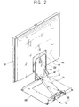
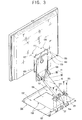
- a monitor support to which a monitor 120 is attached comprises a base member 130 which may be stood on an installation plane such as a desk or mounted on a wall, a link member 10 linking the monitor 120 with the base member 130, and a main bracket 170 disposed between the monitor 120 and the link member 10.
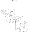
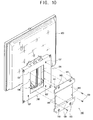
- the monitor support also includes a pivot part 150 to enable the monitor 120 to pivot on the main bracket 170 so that the monitor may be rotated about an axis extending substantially at right angles to the plane of the monitor screen, and a monitor bracket 180 detachably mounted to the monitor 120 and situated between the monitor 120 and the main bracket 170.
- the pivot part 150 includes a first circular through hole 171 formed in the main bracket 170, a second circular through hole 181 formed in the monitor bracket 180, a plurality of washers 151 aligned with the first and second through holes 171,181, and a hub 153 which locates through the first and second through holes 171,181 to enable the main and monitor brackets 170,180 to pivot relative to each other against a frictional force connecting them together.
- the second through hole 181 is formed in a raised part 183 of the monitor bracket 180 which extends toward the main bracket 170.
- the hub 153 is inserted through the first through holes 171, a washer 151, the second through hole 181 and then the remaining washers. The end of the hub 153 is then hammered to splay its end to form a radially extending rim to prevent removal of the hub 153.
- the washers 151 act as springs to keep a constant friction acting between the main bracket 170 and the monitor bracket 180.
- the hub 153 is a hollow cylindrical member defining a through hole 155 for a cable 122 to pass and to electrically connect the monitor 120 to a power source.
- the pivot part 150 further includes a pivot angle restricting part 160 to restrict the angle through which the monitor bracket 180 may rotate relative to the main bracket 170.
- the pivoting angle restricting part 160 includes a pivot projection 161 protruding from a surface of the main bracket 170 adjacent to the first through hole 171, and a guide slot 163 having an arcuate shape formed in the raised part 183 of monitor bracket 180 adjacent to and coaxial with the second through hole 181.
- the guide slot 163 receives the pivot projection 161 and restricts movement of the pivot projection 161 beyond the extremities of the guide slot 163.
- the pivot projection 161 is formed by partially cutting a U-shaped slot in the main bracket 170 adjacent to the first through hole 171 to form a tab and then by subsequently bending the tab by 90° so that it upstands from the surface of the main bracket 170.
- the angle through which the monitor 120 may pivot is restricted to within 180° from left to right as shown in Figures 6A and 6B by the guide slot 163.
- any other pivoting angle limits may alternatively be enabled.
- pivot projection 161 may be provided on the monitor bracket 180, and the guiding slot 163 may be provided on the main bracket 170.
- the monitor bracket 180 has through holes 185 at its corners to enable attachment to the monitor 120.
- the rear of monitor 120 has a plurality of screw holes 125 that correspond in position so the through holes 185 in the monitor bracket 180.
- First screws 126 are used to attach the monitor 120 to the monitor bracket 180.
- the through holes 185 of the monitor bracket 180 and the screw holes 125 of the monitor main body 120 are located in accordance with standards set by VESA, so that a user may use any monitor with the monitor bracket 180.
- the monitor bracket 180 has a pair of first hooks 187 extending from an upper edge of the monitor bracket 180 to enable the monitor bracket 180 to be attached to the rear of the monitor 120 easily.
- the rear of the monitor 120 has a corresponding pair of first hook receivers 127 to receive the first hooks 187 when the monitor bracket 180 and monitor 120 are mounted to each other.
- the link member 10 has a lower end 10a pivotally mounted to the base member 130 via a base hinge 20 and an upper end 10b rotatably combined to the main bracket 170 via a main hinge 70.
- the base hinge 20 includes a pair of first and second supporting brackets 23,27 spaced from each other at a predetermined distance and fastened onto the base member 130 with second screws 131
- the main hinge 70 includes a pair of third and fourth supporting brackets 73,77 spaced from each other at a predetermined distance and fastened onto the main bracket 170 with third screws 173.
- the base member 130 has a link member accommodating part 135 in a central region thereof to accommodate the link member 10.
- the base hinge 20 includes first and second base hinge parts 30,40 to pivotally mount opposite sides of the lower end 10a of the link member 10 to the first and second supporting brackets 23,27, respectively.
- the first base hinge part 30 includes a first pin accommodating part 31 formed on a first side of the lower end 10a of the link member 10, a first pin supporting part 32 formed inside the first supporting bracket 23, and a first hinge pin 33 having a first end rotatably inserted in the first pin accommodating part 31 and a second end fixedly fitted into the first pin supporting part 32.
- the first base hinge part 30 also includes a first frictional spring 34 interposed between the first hinge pin accommodating part 31 and the first hinge pin 33, to provide a force to resist rotation of the link member 10 about the first hinge pin 33.
- the first frictional spring 34 is shaped like a flat spring and has a first end to which the first hinge pin 33 is fixedly fitted, and a second end combined to the first pin accommodating part 31.
- the first frictional spring 34 fastened to the link member 10 is rotatably combined to the first hinge pin 33 fastened to the first supporting bracket 23 with a predetermined friction. It is preferable that the friction is stronger than torque generated due to the weight of the monitor 120, the link member 10 and the main bracket 170.
- the first supporting bracket 23 includes a spring supporting part 24 on which is provided a torsion spring 35 having a bias that acts in a direction against downward rotation of the link member 10 against the base member 130.
- the torsion spring 35 has a first end supported by the first supporting bracket 23, and a second end supported by the link member 10. It is preferable that the biasing force of the torsion spring 35 is approximately equal to the torque generated due to the weight of the monitor 120. Thus, because the weight of the monitor 120 and the bias of the torsion spring 35 offset each other, the user may easily rotate the link member 10 against the base member 130 with a small force which is only strong enough to overcome the friction between the first frictional spring 34 and the first hinge pin 33.
- the second base hinge part 40 includes a second pin accommodating part 41 formed on a second side of the lower end 10a of the link member 10, a second pin supporting part 42 formed inside the second supporting bracket 27, and a second hinge pin 43 having a first end rotatably inserted in the second pin accommodating part 41 and a second end fitted in the second pin supporting part 42.
- the second base hinge part 40 also includes a first link supporting part 45 incorporated with the second end of the second hinge pin 43.
- the first link supporting part 45 is provided between the opposite sides of the lower end 10a of the link member 10.
- the first link supporting part 45 is incorporated with the second hinge pin 43 fitted into the second supporting bracket 27, and the second hinge pin 43 is rotatably inserted into the second pin accommodating part 41.
- the second base hinge part 40 is provided with a rotating angle restricting part 50 to restrict the angle of rotation of the link member 10 relative to the base member 130 within a predetermined range.
- the rotating angle restricting part 50 includes a pair of fan shaped grooves 51 formed on an outside of the second side of the lower end 10a of the link member 10, around the second pin accommodating part 41, and radially opposed to each other.
- a corresponding pair of stoppers 53 is provided around the second pin supporting part 42 of the second supporting bracket 27.
- One stopper engages with a corresponding fan shaped groove 51 when the link member is rotated in one direction and the other stopper engages with the other groove when the link member is rotated in the opposite direction.
- the angular range may be 0° through 60°. However, the angular range may be altered by changing the design of the fan shaped grooves 51 and the stoppers 53.
- the main hinge 70 includes first and second main hinge parts 80,90 to rotatably combine opposite sides of the upper end 10b of the link member 10 to the third and fourth supporting brackets 73,77, respectively.
- the third and fourth supporting brackets 73,77 have first ends fastened onto a lower part of the main bracket 170 with the third screws 173.
- the third and fourth supporting brackets 73,77 also have second ends, each provided with second and third frictional springs 84,94 which are shaped like a flat spring and to which third and fourth hinge pins 83,93 (to be described later) are rotatably inserted with a predetermined friction.
- the first main hinge part 80 includes a third pin supporting part 82 formed on a first side of the upper end 10b of the link member 10, and a third hinge pin 83 has its first end fixedly fitted into the third pin supporting part 82.
- the first main hinge part 80 also includes the second frictional spring 84 incorporated with the third supporting bracket 73 to rotatably accommodate a second end of the third hinge pin 83 therein, with a force that resists rotation of the supporting bracket 73 about the third hinge pin 83. That is, the third hinge pin 83 is fitted into the third pin supporting part 82 of the link member 10, and rotatably inserted in the second frictional spring 84 incorporated with the third supporting bracket 73 with a predetermined friction.
- the second main hinge part 90 includes a third pin accommodating part 91 formed on a second side of the upper end 10b of the link member 10, a second link supporting part 95 provided between the opposite sides of the upper end 10a of the link member 10, and a fourth hinge pin 93 having a first end incorporated with the second link supporting part 95 and rotatably inserted in the third pin accommodating part 91.
- the second main hinge part 90 also includes the third frictional spring 94 incorporated with the fourth supporting bracket 77 to rotatably accommodate a second end of the fourth hinge pin 93 therein, with a force resisting rotation of the fourth hinge pin 93.
- the fourth hinge pin 93 is rotatably inserted in the third pin accommodating part 91 of the link member 10, and rotatably accommodated in the third frictional spring 94 incorporated with the fourth supporting bracket 77 with a predetermined friction.
- the second link supporting part 95 is provided between the opposite sides of the upper end 10b of the link member 10, and incorporated with the fourth hinge pin 93.
- the first and second link supporting parts 45,95 are linked by auxiliary link members 100,110 (to be described later), so that the second link supporting part 95 is rotated together with the auxiliary link members 100, 110.
- the second link supporting part 95 and the auxiliary link members 100,110 do not rotate because only the second and third frictional springs 84,94 incorporated with the main bracket 170 are rotated about the third and fourth hinge pins 83,93 respectively.
- the second main hinge part 90 includes a tilting angle restricting part 55 to restrict a tilting angle of the monitor 120 relative to the link member 10 within a predetermined range.
- the tilting angle restricting part 55 includes an arc cutting part 56 formed by partially cutting the fourth supporting bracket 77 adjacent to the third frictional spring 94.
- the tilting angle restricting part 55 also includes a tilting restricting washer 57 formed with a through hole 58 and fixedly fitted on the fourth hinge pin 93 so as to rotate together with the fourth hinge pin 93, and a projection 59 which selectively engages with opposite ends of the arc cutting part 56 according to a tilting direction of the monitor 120.
- the tilt angle of the monitor 120 against the link member 10 is restricted within a predetermined angle.
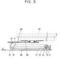
- the monitor 120 can be tilted in a backward direction relative to the link member 10, and may be completely laid on the link member 10 as shown in Figure 9. Further, an angular range through which the monitor may tilt can be altered by changing the design of the arc cutting part 56 and the projection 59 of the tilting restricting washer 57.
- the link member 10 may by rotated in forward and backward directions against the base member 130, and the monitor 120 may be tilted relative to the link member 10 within a predetermined range.
- rotation of the link member 10 relative to the base member 130 may be interlinked with rotation of the monitor main body 120 relative to the link member 10.
- the auxiliary link members 100,110 transmit a rotating motion of the link member 10 against the base member 130 to a tilting motion of the monitor main body 120.
- the auxiliary link members 100,110 are bar shaped and are rotatably combined to the first and second link supporting parts 45,95.
- auxiliary link accommodating parts 46,96 are provided to which opposite ends of the auxiliary link members 100,110 are inserted.
- a plurality of pin holes 47,97 spaced from each other at a predetermined distance to communicate with the auxiliary link accommodating parts 46,96.
- On the opposite ends of the auxiliary link members 100,110 are formed through holes 100a,110a to be aligned with the pin holes 47,97 respectively.
- the tilt of the monitor 120 and the rotation of the link member 10 are controlled as follows.
- the second and third frictional springs 84,94 incorporated with the main bracket 170 are rotated about the third and fourth hinge pins 83,93.
- the tilting angle of the monitor main body 120 against the link member 10 is restricted within a predetermined angle by part of the arc cutting part 56 of the fourth supporting bracket 77, and the projection 59 of the tilting restricting washer 57 fitted on the fourth hinge pin 93.
- the monitor main body 120 is tilted in the backward direction against the link member 10, and may be completely laid on the link member 10 (refer to Figure 9).
- the second link supporting part 95 provided between the opposite sides of the upper end 10b of the link member 10 is rotated in a clockwise direction at a predetermined angle by part of the auxiliary link members 100,110.
- the rotating motion of the second link supporting part 95 is transmitted to the fourth hinge pin 93 and the fourth supporting bracket 77 is rotated together with the fourth hinge pin 93, thereby tilting the monitor main body 120.
- the reason that the fourth hinge pin 93 and the fourth supporting bracket 77 work together is that predetermined friction is provided between the fourth hinge pin 93 and the third frictional spring 94 of the fourth supporting brackets 77.
- the tilt of the monitor main body 120 against the link member 10 is interlocked with the rotation of the link member 10 against the base member 130, so that the monitor main body 120 is controlled in height while maintaining a tilt position. Further, interlocking motion between the monitor main body 120 and the link member 10 may be adjusted by changing a length and position of the auxiliary link members 100,110.
- the link member 10 is more forwardly pressed, the link member 10 is rotated until one of the fan shaped grooves 51 formed on the lower end 10a of the link member 10 is engaged with one of the stoppers 53 formed on the second supporting bracket 27.
- the link member 10 is not forwardly rotated anymore.
- the monitor main body 120 is downwardly pressed toward the base member 130, the monitor main body 120 may be completely laid on the base member 130 (refer to Figure 9).
- a process of altering the monitor of the present invention from a completely folded state into an unfolded state is performed in reverse to the above.
- the monitor main body 120 is completely laid on the base member 130, a packing volume of the monitor is decreased, thereby decreasing costs to store and carry the monitor.
- the monitor according to the present invention further includes a base bracket 140 having one side mountable to the rear of the base member 130 so that the other side can be mounted onto an inclined plane such as a wall or an arm stand, etc.
- the base bracket 140 is formed with a plurality of second hooks 141 that engage with a plurality of second hook holders 137 formed on the base member 130 to attach the base bracket 140 onto the rear of the base member 130.
- the base bracket 140 is also formed with a plurality of first combining holes 143 to attach the base bracket 140 to an inclined plane, and a plurality of second combining holes 145 to attach the base bracket 140 with the base member 130.
- the base member 130 is formed with a plurality of third combining holes 138 in correspondence to the second combining holes 145 of the base bracket 140, so that the base bracket 140 is combined to the base member 130 with a plurality of fourth screws 139.
- the second combining holes 145 of the base bracket 140 and the third combining holes 138 of the base member 130 are spaced according to the VESA, so that the monitor may be installed onto various arm stands complying with this standard.
- FIG 11 is a sectional view illustrating a monitor being mounted to an arm stand.
- an arm stand 190 is provided with a monitor supporting part 191 at an upper part thereof, and the monitor supporting part 191 is formed with a plurality of fourth combining holes 193 according to the VESA. Therefore, the third combining holes 138 of the base member 130 are aligned with the fourth combining holes 193 of the monitor supporting part 191. Fifth screws 195 are then inserted into the third combining holes 138 formed on the base member 130 at a rear of the monitor supporting part 171 by passing through the fourth combining holes 193 of the monitor supporting part 191.
- the monitor may be easily mounted on various arm stands according to the VESA.
- the torsion spring 35 is provided in the first base hinge part 30.
- the torsion spring may be provided in at least one of the first and second base hinge parts.
- the rotating angle restricting part 50 is provided in the second base hinge part 40.
- the rotating angle restricting part may be provided in at least one of the first and second base hinge parts.
- the tilting angle restricting part 55 to restrict the tilting angle of the monitor main body 120 is provided in the second main hinge part 90.
- the tilting angle restricting part may be provided in at least one of the first and second main hinge parts.
- the present invention provides a monitor in which a monitor main body is controlled in tilt, planar rotation, and height, while maintaining tilt position regardless of the height control.
- the present invention provides a monitor which properly adjusts a tilting angle of a monitor main body against a base member, and decreases costs to store and carry the monitor by decreasing the packing volume thereof.
- the present invention provides a monitor in which a base member is installed onto an inclined plane such as a wall, an arm stand, etc., and more particularly, a monitor which is easily installed onto various arm stands according to VESA.
Landscapes
- Engineering & Computer Science (AREA)
- General Engineering & Computer Science (AREA)
- Mechanical Engineering (AREA)
- Theoretical Computer Science (AREA)
- Human Computer Interaction (AREA)
- Physics & Mathematics (AREA)
- General Physics & Mathematics (AREA)
- Devices For Indicating Variable Information By Combining Individual Elements (AREA)
- Pivots And Pivotal Connections (AREA)
Claims (51)
- Bildschirmtragevorrichtung, einen Tragarm (10), einen Tragbock (170), der mit einem Ende des Tragarms (10) verbunden ist, und eine Tragplatte (180) zum Anbringen an einem Bildschirm umfassend, wobei der Tragbock (170) und die Tragplatte (180) Kupplungseinrichtungen (151, 153) zum Montieren eines Bildschirms an dem Tragarm (10) umfassen, wobei die Kupplungseinrichtungen (151, 153) so betätigt werden können, dass Drehung der Tragplatte (180) relativ zu dem Tragbock (170) ermöglicht wird, dadurch gekennzeichnet, dass das andere Ende (10a) des Tragarms (10) schwenkbar mit einer Basis (130) verbunden ist.
- Bildschirmtragevorrichtung nach Anspruch 1, wobei die Kupplungseinrichtungen (151, 153) ein Nabenelement (153), das sich zwischen der Tragplatte (180) und dem Tragbock (170) erstreckt, umfassen, wobei die Tragplatte (180) und/oder der Tragbock (170) drehbar an dem Nabenelement (153) montiert sind.
- Bildschirmtragevorrichtung nach Anspruch 2, wobei der Tragbock (170) und die Tragplatte (180) jeweils eine entsprechende Öffnung (171, 181) zum Aufnehmen des Nabenelements (153) aufweisen.
- Bifdschirmtragevorrichtung nach Anspruch 3, wobei wenigstens eine Zwischenscheibe (151) an der Nabe (153) zwischen dem Tragbock (170) und der Tragplatte (180) angeordnet ist.
- Bildschirmtragevorrichtung nach einem der Ansprüche 2 bis 4, wobei das Nabenelement (153) an jedem Ende einen radial vorstehenden Kranz aufweist.
- Bildschirmtragevorrichtung nach Anspruch 5, wobei wenigstens eine Zwischenscheibe (151) so an dem Nabenelement (153) zwischen einem Kranz und dem Tragbock (170) und/oder der Tragplatte (180) angeordnet ist, dass die Tragplatte (180) und der Tragbock (170) mit einer vorgegebenen Reibungskraft zusammengehalten werden, die überwunden werden muss, um die Tragplatte (180) relativ zu dem Tragbock (170) zu drehen.
- Bildschirmtragevorrichtung nach Anspruch 6, wobei der Kranz an einem Ende des Nabenelements (153) nach Einfügen der Nabe (153) durch die Öffnung (181) in der Tragplatte (180) und dem Tragbock (170) durch Ausschrägen des Endes des Nabenelements (153) gebildet wird.
- Bildschirmtragevorrichtung nach einem vorhergehenden Anspruch, eine Einrichtung (160) zum Beschränken des Drehwinkels der Tragplatte (180) relativ zu dem Tragbock (170) umfassend.
- Bildschirmtragevorrichtung nach Anspruch 8, wobei die Einrichtung (160) einen gekrümmten Führungsschlitz (163) entweder in der Tragplatte (180) oder in dem Bock (170) koaxial zu den Öffnungen (171, 181) bzw. einen entsprechenden Vorsprung (161) entweder in dem Tragbock (170) oder in der Platte (180) umfasst, wobei der Führungsschlitz (163) und der Vorsprung (161) zusammenwirken, um den Winkel zu beschränken, in dem sich die Tragplatte (180) relativ zu dem Tragbock (170) drehen kann.
- Bildschirmtragevorrichtung nach Anspruch 9, wobei die Tragplatte (180) einen Bereich (183) aufweist, der aus der Ebene der Tragplatte (180) herausgewölbt ist und sich in Richtung des Tragbocks (170) erstreckt, wobei die Öffnung (181) und der Führungsschlitz (163) in dem gewölbten Bereich (183) ausgebildet sind.
- Bifdschirmtragevorrichtung nach Anspruch 10, wobei sich der gewölbte Bereich (183) in der Mitte der Tragplatte (180) befindet.
- Bildschirmtragevorrichtung nach einem der Ansprüche 2 bis 10, wenn von Anspruch 2 abhängig, wobei das Nabenelement (153) ein Loch (155) aufweist, das sich durch die Mitte davon erstreckt, um einem Kabel zu ermöglichen, dort hindurch zu laufen, um mit einem an der Tragplatte (180) angebrachten Bildschirm verbunden zu werden.
- Bildschirmtragevorrichtung nach einem vorhergehenden Anspruch, wobei die Verbindung mit der Basis (130) Drehung des Tragarms (10) um eine erste Achse herum relativ zu der Basis (130) ermöglicht, wobei der Tragbock (170) schwenkbar mit dem Ende des Tragarms (10) verbunden ist, um sich um eine zu der ersten Achse parallele zweite Achse herum zu drehen.
- Bildschirmtragevorrichtung nach Anspruch 13, wobei der Tragbock (180) wenigstens ein Schraubenloch (185) dort hindurch umfasst, um das Befestigen eines Bildschirms (120) an dem Tragbock (180) zu ermöglichen.
- Bildschirmtragevorrichtung nach Anspruch 14, wobei die Schraubenlöcher (185) nach Normen der Video Electronic Standard Association (VESA) positioniert sind.
- Bildschirmtragevorrichtung nach einem der Ansprüche 13 bis 15, wobei der Tragbock (180) mit wenigstens einem ersten Haken (187) ausgebildet ist, der sich von einer Kante davon erstreckt, um in eine entsprechende Öffnung (127) an einer Rückseite eines Bildschirms (120) aufgenommen zu werden.
- Bildschirmtragevorrichtung nach einem der Ansprüche 13 bis 16, einen Basisbock (140) umfassend, der an der Basis (130) angebracht werden kann, um das Montieren der Basis (130) an einer geneigten Ebene zu ermöglichen, wobei der Basisbock (140) mit wenigstens einem Haken (141) ausgestattet ist, der mit wenigstens einem entsprechenden Schlitz (137), der in der Basis (130) ausgebildet ist, in Eingriff gebracht werden kann.
- Bildschirmtragevorrichtung nach Anspruch 17, wobei der Basisbock (140) mit wenigstens einem Sicherungsloch (143) ausgestattet ist, um das Befestigen des Basisbocks (140) an einer geneigten Ebene zu ermöglichen.
- Bildschirmtragevorrichtung nach Anspruch 17 oder Anspruch 18, wobei der Basisbock (140) mit wenigstens einem Verbindungsloch (145) ausgestattet ist, um das Verbinden des Basisbocks (140) mit der Basis (130) zu ermöglichen, und die Basis (130) mit wenigstens einem Verbindungsloch (138), das dem Verbindungsloch (145) des Basisbocks (140) entspricht, ausgestattet ist.
- Bildschirmtragevorrichtung nach Anspruch 19, wobei das Verbindungsloch (145) des Basisbocks (140) und das Verbindungsloch (138) der Basis (130) nach Normen der Video Electronic Standard Association (VESA) positioniert sind.
- Bitdschirmtragevorrichtung nach einem der Ansprüche 93 bis 20, des Weiteren ein Basisdrehgelenk umfassend, das das andere Ende (10a) des Tragarms (10) schwenkbar an der Basis (130) anbringt, wobei das Basisctrehgelenk ein Paar eines ersten und zweiten Tragbocks (23, 27), die mit einem vorgegebenen Abstand voneinander beabstandet sind und an der Basis (130) befestigt sind, und ein erstes und zweites Basisdrehgelenkteil (30, 40) zum drehbaren Kombinieren gegenüberliegender Seiten des anderen Endes (10a) des Tragarms (10) mit dem ersten bzw. zweiten Tragbock (23, 27) umfasst.
- Bildschirmtragevorrichtung nach Anspruch 21, wobei das erste Basisdrehgelenkteil (30) ein erstes Stiftunterbringteil (31), das an einer ersten Seite des anderen Endes (10a) des Tragarms (10) ausgebildet ist, ein erstes Stifttrageteil (32), das in dem ersten Tragbock (23) ausgebildet ist, einen ersten Drehgefenkstift (33), bei dem ein erstes Ende drehbar in das erste Stiftunterbringteil (31) eingefügt ist und ein zweites Ende in das erste Stifttrageteil (32) eingepasst ist, und eine erste Reibfeder (34), die zwischen dem ersten Stiftunterbringteil (31) und dem ersten Drehgelenkstift (33) angeordnet ist und eine der Drehung des ersten Drehgelenkstifts (33) widerstehende Kraft aufweist, umfasst.
- Bildschirmtragevorrichtung nach Anspruch 21 oder 22, wobei der erste Tragbock (23) ein Federtrageteil (24) umfasst, das nach innen vorsteht und mit einer Drehfeder (35) daran ausgestattet ist, die eine Elastizität aufweist, um in eine entgegengesetzte Richtung zu einer Abwärtsdrehung des Tragarms (10) gegen die Basis (130) zu wirken.
- Bildschirmtragevorrichtung nach einem der Ansprüche 21 bis 23, wobei das zweite Basisdrehgelenkteil (40) ein zweites Stiftunterbringteil (41), das an einer zweiten Seite des anderen Endes (10a) des Tragarms (10) ausgebildet ist, ein zweites Stifttrageteil (42), das in dem zweiten Tragbock (27) ausgebildet ist, einen zweiten Drehgelenkstift (43), bei dem ein erstes Ende drehbar in das zweite Stiftunterbringteil (41) eingefügt ist und ein zweites Ende in das zweite Stifttrageteil (42) eingepasst ist, und ein erstes Verbindungstrageteil (45), das fest in den zweiten Tragbock (27) eingepasst ist und mit dem zweiten Ende des zweiten Drehgelenkstifts (43) integriert ist, umfasst.
- Bildschirmtragevorrichtung nach einem der Ansprüche 21 bis 24, wobei wenigstens eines des ersten und zweiten Drehgelenkteils (30, 40) mit einem Drehwinkelbeschränkungsteil (50) ausgestattet ist, um einen Drehwinkel des Tragarms (10) gegen die Basis (130) in einem vorgegebenen Bereich zu beschränken.
- Bildschirmtragevorrichtung nach Anspruch 25, wobei das Drehbeschränkungsteil (50) ein Paar fächerförmige Nuten (51), die an der zweiten Seite des anderen Endes (10a) des Tragarms (10) um das zweite Stiftunterbringteil (41) herum einander gegenüberliegend ausgebildet sind, und ein Paar Anschläge (53), die um das zweite Stifttrageteil (42) des zweiten Tragbocks (27) herum bereitgestellt sind und nach einer Drehrichtung des Tragarms (10) selektiv mit dem Paar fächerförmiger Nuten (51) in Eingriff kommen, umfasst.
- Bildschirmtragevorrichtung nach einem der Ansprüche 24 bis 26, des Weiteren ein Hauptdrehgelenk umfassend, das das Ende (10b) des Tragarms (10) schwenkbar an dem Tragbock (170) anbringt, wobei das Hauptdrehgelenk ein Paar eines dritten und vierten Tragbocks (73, 77), die mit einem vorgegebenen Abstand voneinander beabstandet sind und an dem Tragbock (170) befestigt sind, umfasst, wobei das Hauptdrehgelenk ein erstes und zweites Hauptdrehgelenkteit (80, 90) zum drehbaren Kombinieren gegenüberliegender Seiten des Endes (10b) des Tragarms (10) mit dem dritten bzw. vierten Tragbock (73, 77) umfasst.
- Bildschirmtragevorrichtung nach Anspruch 27, wobei das erste Hauptdrehgelenkteil (80) ein drittes Stifttrageteil (82), das an einer ersten Seite des Endes (10b) des Tragarms (10) ausgebildet ist, einen dritten Drehgelenkstift (83), bei dem ein erstes Ende in den dritten Stifttrageteil (82) gepasst ist, und eine zweite Reibfeder (84), die mit dem dritten Tragbock (73) integriert ist, um ein zweites Ende des dritten Drehgeienkstifts (83) darin unterzubringen, und eine der Drehung des dritten Drehgelenksfifts (83) widerstehende Kraft aufweist, umfasst.
- Bildschirmtragevorrichtung nach Anspruch 28, wobei das zweite Hauptdrehgelenkteil (90) ein drittes Stiftunterbringteil (91), das an einer zweiten Seite des Endes (10b) des Tragarms (10) ausgebildet ist, ein zweites Verbindungstrageteil (95), das zwischen den gegenüberliegenden Seiten des Endes (10b) des Tragarms (10) bereitgestellt ist, einen vierten Drehgelenkstift (93), bei dem ein erstes Ende mit dem zweiten Verbindungstrageteil (95) integriert ist und drehbar in den dritten Stiftunterbringteit (91) eingefügt ist, und eine dritte Reibfeder (94), die mit dem vierten Tragbock (77) integriert ist, um ein zweites Ende des vierten Drehgelenkstifts (93) darin unterzubringen, und eine der Drehung des vierten Drehgelenkstifts (93) widerstehende Kraft aufweist, umfasst.
- Bildschirmtragevorrichtung nach einem der Ansprüche 27 bis 29, wobei das zweite Hauptdrehgelenkteil (90) ein Kippwinkelbeschränkungsteil (55) umfasst, um einen Kippwinkel eines Bitdschirmhauptkörpers (120) gegen den Tragarm (10) in einem vorgegebenen Bereich zu beschränken.
- Bildschirmtragevorrichtung nach Anspruch 30, wobei das Kippwinkelbeschränkungsteil (55) ein Bogenschnittteil (56), das an dem vierten Tragbock (77) angrenzend an die dritte Reibfeder (94) ausgebildet ist, und eine Kippbeschränkungszwischenscheibe (57), die mit einem Zwischenscheibendurchgangsloch (58) ausgebildet ist und fest auf den vierten Drehgetenkstift (93) gepasst ist, und einen Vorsprung (59), der nach einer Kipprichtung eines Bildschirmhauptkörpers (120) selektiv mit gegenüberliegenden Enden des Bogenschnittteils (56) in Eingriff gebracht wird, umfasst, wobei der Kippwinkel eines Bitdschirnnhauptkörpers (120) gegen den Tragarm (10) in einem vorgegebenen Bereich beschränkt ist.
- Bildschirmtragevorrichtung nach einem der Ansprüche 29 bis 31, wobei ein Schwenkverbindungsmechanismus (45, 95, 100, 110) des Bildschirmtragarms ein Paar Hilfsverbindungselemente (100, 110) umfasst, die drehbar mit dem ersten und zweiten Verbindungstragteil (45, 95) kombiniert sind.
- Bildschirmtragevorrichtung nach Anspruch 32, wobei das erste und zweite Verbindungstragteil (45, 95) mit einer Vielzahl von Stiftlöchern (47, 97), die mit einem vorgegebenen Abstand voneinander beabstandet sind, ausgestattet sind, und an gegenüberliegenden Enden der Hilfsverbindungselemente (100, 110) Durchgangslöcher (100a, 110a), die mit den Stiftlöchern (47, 97) auszurichten sind, bereitgestellt sind.
- Bildschirmtragevorrichtung nach Anspruch 33, des Weiteren eine Vielzahl von Verbindungskupplungsstiften (102) umfassend, die durch die Stiftlöcher (47, 97) des ersten und zweiten Verbindungstragteils (45, 95) und die Stiftdurchgangslöcher (100a, 110a) der Hilfsverbindungselemente (100, 110) Durchgangslöcher (100a, 110a) eingefügt werden, um die Hilfsverbindungselemente (100,110) mit dem ersten und zweiten Verbindungstragteil (45, 95) zu koppeln.
- Bildschirmtragevorrichtung nach einem der Ansprüche 13 bis 34, des Weiteren ein Tragarmunterbringteil (135) umfassend, das an einer Mitte der Basis (130) bereitgestellt ist, um den Tragarm (10) unterzubringen.
- Bildschirmtragevorrichtung nach Anspruch 22, wobei die erste Reibfeder (34) ein erstes Ende, das an den ersten Drehgelenkstift (33) gepasst ist, und ein zweites Ende, das mit dem ersten Stiftunterbringteil (31) kombiniert ist, umfasst.
- Bildschirmtragevorrichtung nach Anspruch 36, wobei die erste Reibfeder (34) an dem Tragarm (10) befestigt ist und drehbar mit dem ersten Drehgelenkstift (33), der mit einer vorgegebenen Reibung an dem ersten Tragbock (23) befestigt ist, kombiniert ist.
- Bildschirmtragevorrichtung nach Anspruch 37, wobei die vorgegebene Reibung stärker ist als ein Drehmoment auf Grund eines Gewichts eines Bildschirmhauptkörpers (120).
- Bildschirmtragevorrichtung nach Anspruch 23, wobei die Drehfeder (35) ein erstes Ende, das von dem ersten Tragbock (23) getragen wird, und ein zweites Ende, das von dem Tragarm (10) getragen wird, umfasst, wobei eine Kraft veranlasst wird, in eine entgegengesetzte Richtung zu einer Vorwärtsdrehung eines mit dem Tragarm (10) verbundenen Bildschirmhauptkörpers (120) zu wirken.
- Bildschirmtragevorrichtung nach Anspruch 23 oder Anspruch 39, wobei die Elastizität der Drehfeder (35) einem Drehmoment auf Grund eines Gewichts eines Bildschirmhauptkörpers (120) entspricht, wobei ermöglicht wird, dass das Gewicht und die Elastizität einander ausgleichen und den Tragarm (10) mit einer geringen Kraft gegen die Basis (130) drehen.
- Bildschirmtragevorrichtung nach Anspruch 32, wobei das erste und zweite Verbindungstragteil (45, 95) durch die Hilfsverbindungselemente (100, 110) so verbunden sind, dass das zweite Verbindungstragteil (95) zusammen mit den Hilfsverbindungselementen (100,110) gedreht wird.
- Bildschirmtragevorrichtung nach Anspruch 32 oder Anspruch 41, wobei dann, wenn ein Bildschinnhauptkörper (120) in Aufwärts- und Abwärtsrichtungen gegen den Tragarm (10) gekippt werden kann, die zweite und dritte Reibfeder (84, 94) um den dritten und vierten Drehgelenkstift (83, 93) herum gedreht werden, wobei das Drehen der Hilfsverbindungselemente (100, 110) und des zweiten Verbindungstragteils (95) verhindert wird.
- Bildschirmtragevorrichtung nach Anspruch 42, wobei eine Reibung zwischen dem dritten Drehgelenkstift (83) und der zweiten Reibfeder (84) und eine Reibung zwischen dem vierten Drehgelenkstift (93) und der dritten Reibfeder (94) stärker sind als ein Drehmoment auf Grund eines Gewichts eines Bildschirmhauptkörpers (120).
- Bildschirmtragevorrichtung nach Anspruch 31, wobei ein Bereich des Kippwinkels durch eine Konstruktion des Bogenschnittteils (56) und des Vorsprungs (59) der Kippbeschränkungszwischenscheibe (57) bestimmt wird.
- Bildschirmtragevorrichtung nach Anspruch 32, wobei die Hilfsverbindungselemente (100, 110) eine Drehbewegung des Tragarms (10) gegen die Basis (130) in eine Kippbewegung eines Bildschirmhauptkörpers (120) übertragen.
- Bildschirmtragevorrichtung nach einem der Ansprüche 13 bis 45, wobei ein Bildschirmhaupikörper (120) in eine Rückwärtsrichtung gegen den Tragarm (10) gekippt werden kann, um parallel zu dem Tragarm (10) zu liegen.
- Bildschirmtragevorrichtung nach Anspruch 29, wobei eine Drehbewegung des zweiten Verbindungstragteils (95) zu dem vierten Drehgelenkstift (93) übertragen wird und der vierte Tragbock (77) zusammen mit dem vierten Drehgelenkstift (93) gedreht wird, wobei ein Bildschirmhauptkörper (120) gekippt wird.
- Bildschirmtragevorrichtung nach einem der Ansprüche 13 bis 47, wobei ein Kippen eines Bildschirmhauptkörpers (120) gegen den Tragarm (10) so mit einer Drehung des Tragarms (10) gegen die Basis (130) verblockt wird, dass ein Bildschirmhauptkörper (120) in der Höhe gesteuert wird, während eine Kippposition beibehalten wird.
- Bildschirmtragevorrichtung nach Anspruch 17, des Weiteren einen Armständer (190) umfassend, der mit einem Bildschirmtrageteil (191) mit wenigstens einem nach VESA-Normen positionierten Verbindungsloch (193) ausgestattet ist.
- Bildschirmtragevorrichtung nach Anspruch 49, wobei das Verbindungsloch (138) der Basis (130) mit dem Verbindungsloch (193) des Bitdschirmtragteils (191) ausgerichtet ist, um die Basis (130) so an dem Büdschirmtragteil (191) zu befestigen, dass ein Bildschirm an dem Armständer (190) montiert werden kann.
- Bildschirmtragevorrichtung nach einem vorhergehenden Anspruch, einen Schwenkverbindungsmechanismus (45, 95, 100, 110) umfassend, der sich zwischen der Basis (130) und dem Tragbock (170) erstreckt und betätigt werden kann, um den Tragbock (170) zu veranlassen, sich relativ zu dem Tragarm (10) zu drehen, wenn sich der Tragarm (10) relativ zu der Basis (130) dreht.
Applications Claiming Priority (2)
| Application Number | Priority Date | Filing Date | Title |
|---|---|---|---|
| KR10-2002-0041617A KR100512718B1 (ko) | 2002-07-16 | 2002-07-16 | 모니터장치 |
| KR2002041617 | 2002-07-16 |
Publications (3)
| Publication Number | Publication Date |
|---|---|
| EP1382897A2 EP1382897A2 (de) | 2004-01-21 |
| EP1382897A3 EP1382897A3 (de) | 2004-12-15 |
| EP1382897B1 true EP1382897B1 (de) | 2007-04-25 |
Family
ID=36819140
Family Applications (1)
| Application Number | Title | Priority Date | Filing Date |
|---|---|---|---|
| EP03253172A Expired - Lifetime EP1382897B1 (de) | 2002-07-16 | 2003-05-21 | Bildschirmtragevorrichtung |
Country Status (6)
| Country | Link |
|---|---|
| US (1) | US6822857B2 (de) |
| EP (1) | EP1382897B1 (de) |
| JP (1) | JP3850393B2 (de) |
| KR (1) | KR100512718B1 (de) |
| CN (2) | CN100546448C (de) |
| DE (1) | DE60313400T2 (de) |
Families Citing this family (163)
| Publication number | Priority date | Publication date | Assignee | Title |
|---|---|---|---|---|
| US7604206B2 (en) | 2001-11-19 | 2009-10-20 | Samsung Electronics Co., Ltd. | Monitor improved in a tilting and combining structure |
| KR100520060B1 (ko) | 2002-05-28 | 2005-10-11 | 삼성전자주식회사 | 모니터장치 |
| KR100465792B1 (ko) | 2002-07-06 | 2005-01-13 | 삼성전자주식회사 | 디스플레이장치 |
| KR100630969B1 (ko) | 2002-08-24 | 2006-10-02 | 삼성전자주식회사 | 디스플레이장치 |
| KR100476090B1 (ko) | 2002-09-27 | 2005-03-11 | 삼성전자주식회사 | 모니터장치 |
| KR100482007B1 (ko) | 2002-09-28 | 2005-04-13 | 삼성전자주식회사 | 모니터장치 |
| KR20040032278A (ko) * | 2002-10-08 | 2004-04-17 | 엘지전자 주식회사 | 평판형 디스플레이 모니터의 스탠드 절첩 구조 |
| KR100770981B1 (ko) * | 2002-10-30 | 2007-10-30 | 삼성전자주식회사 | 디스플레이의 스탠드 |
| KR100500234B1 (ko) | 2002-11-05 | 2005-07-11 | 삼성전자주식회사 | 디스플레이장치 |
| KR100826605B1 (ko) | 2002-11-11 | 2008-04-30 | 삼성전자주식회사 | 모니터장치 |
| KR20040042609A (ko) * | 2002-11-15 | 2004-05-20 | 엘지전자 주식회사 | 피봇을 갖는 2절 힌지구조의 영상 표시기기 |
| TW580241U (en) * | 2003-02-21 | 2004-03-11 | Amtran Technology Co Ltd | Improved structure for liquid crystal display |
| KR100770983B1 (ko) * | 2003-04-09 | 2007-10-30 | 삼성전자주식회사 | 모니터장치 |
| KR100770984B1 (ko) | 2003-05-23 | 2007-10-30 | 삼성전자주식회사 | 디스플레이 장치 |
| US7175152B2 (en) * | 2003-07-11 | 2007-02-13 | Csav, Inc. | Display mounting device |
| KR100488534B1 (ko) * | 2003-07-23 | 2005-05-11 | 삼성전자주식회사 | 디스플레이장치 |
| TWM244714U (en) * | 2003-09-05 | 2004-09-21 | Hon Hai Prec Ind Co Ltd | Adjusting apparatus for monitor |
| KR100568181B1 (ko) * | 2003-10-17 | 2006-04-05 | 삼성전자주식회사 | 디스플레이 장치 |
| TWI241141B (en) * | 2003-11-03 | 2005-10-01 | Coretronic Corp | Display stand |
| US6962312B2 (en) * | 2004-01-06 | 2005-11-08 | Amtran Technology Co., Ltd. | Display apparatus with adjustable supporting device |
| KR100526617B1 (ko) * | 2004-03-12 | 2005-11-08 | 삼성전자주식회사 | 모니터장치 |
| KR100531314B1 (ko) * | 2004-03-16 | 2005-11-29 | 엘지전자 주식회사 | 영상표시장치 |
| US7088577B2 (en) * | 2004-03-25 | 2006-08-08 | Dell Products L.P. | System and method for managing information handling system adjustable cables |
| CN100375131C (zh) * | 2004-03-26 | 2008-03-12 | 乐金电子(南京)等离子有限公司 | 图像显示器的固定装置 |
| US20050236533A1 (en) * | 2004-04-27 | 2005-10-27 | Dell Products L.P. | Height adjustable stand for LCD monitor with detachment and lockdown features |
| KR100609852B1 (ko) * | 2004-05-04 | 2006-08-08 | 삼성전자주식회사 | 디스플레이장치 |
| KR100662367B1 (ko) * | 2004-05-06 | 2007-01-02 | 엘지전자 주식회사 | 모니터용 스탠드 어셈블리 |
| KR20050107206A (ko) * | 2004-05-08 | 2005-11-11 | 삼성전자주식회사 | 모니터장치 |
| KR100541457B1 (ko) * | 2004-05-12 | 2006-01-10 | 삼성전자주식회사 | 디스플레이 장치 |
| KR20050109109A (ko) * | 2004-05-13 | 2005-11-17 | 삼성전자주식회사 | 모니터장치 |
| KR100586983B1 (ko) * | 2004-05-21 | 2006-06-08 | 삼성전자주식회사 | 모니터장치 |
| CN2881760Y (zh) * | 2004-06-29 | 2007-03-21 | 英特尔公司 | 计算机显示装置的铰链系统 |
| WO2006000126A1 (en) * | 2004-06-29 | 2006-01-05 | Intel Corporation | Dual mode computer display device |
| US7770856B2 (en) * | 2004-08-13 | 2010-08-10 | Hewlett-Packard Development Company, L.P. | Thin computer monitor support apparatus |
| KR100628119B1 (ko) * | 2004-08-17 | 2006-09-26 | 엘지전자 주식회사 | 평판형 모니터 |
| CA109933S (en) * | 2004-09-16 | 2006-06-19 | Sony Computer Entertainment Inc | Support base for computer unit |
| KR100671298B1 (ko) * | 2004-09-22 | 2007-01-18 | 삼성전자주식회사 | 디스플레이 설치장치 |
| US8608119B2 (en) | 2004-11-23 | 2013-12-17 | Hewlett-Packard Development Company, L.P. | Display stand |
| US7398535B2 (en) | 2004-12-10 | 2008-07-08 | Coby Electronics Corporation | Portable media player |
| KR100596583B1 (ko) * | 2005-02-22 | 2006-07-04 | 삼성전자주식회사 | 모니터장치 |
| JP3110945U (ja) * | 2005-03-02 | 2005-07-07 | 船井電機株式会社 | 液晶表示装置 |
| KR100684997B1 (ko) * | 2005-03-08 | 2007-02-20 | 삼성전자주식회사 | 모니터장치 |
| KR100676325B1 (ko) * | 2005-03-15 | 2007-01-30 | 삼성전자주식회사 | 디스플레이장치 |
| KR100676324B1 (ko) * | 2005-03-15 | 2007-01-30 | 삼성전자주식회사 | 디스플레이장치 |
| US20060237618A1 (en) * | 2005-03-15 | 2006-10-26 | Chiang Sun H | Support device for monitor, display or objects |
| KR100684998B1 (ko) * | 2005-04-21 | 2007-02-20 | 삼성전자주식회사 | 모니터장치 |
| US20060278795A1 (en) * | 2005-06-09 | 2006-12-14 | Michael Lee | Pivotal device for monitors |
| TWM281089U (en) * | 2005-08-04 | 2005-11-21 | Shin Zu Shing Co Ltd | Bi-sectional pivot |
| KR100697446B1 (ko) * | 2005-08-04 | 2007-03-20 | 엘지전자 주식회사 | 영상 디스플레이 장치의 스탠드 |
| KR100705063B1 (ko) | 2005-08-10 | 2007-04-06 | 엘지전자 주식회사 | 영상 디스플레이 장치의 스탠드 |
| KR100658836B1 (ko) * | 2005-08-16 | 2006-12-15 | 엘지전자 주식회사 | 스탠드 장치 |
| US7663868B1 (en) * | 2005-09-10 | 2010-02-16 | Peter Ar-Fu Lam | Display devices mounting apparatus |
| KR20070033211A (ko) * | 2005-09-21 | 2007-03-26 | 삼성전자주식회사 | 디스플레이장치 |
| KR20070033210A (ko) * | 2005-09-21 | 2007-03-26 | 삼성전자주식회사 | 디스플레이장치 |
| KR101164820B1 (ko) * | 2005-09-22 | 2012-07-12 | 삼성전자주식회사 | 디스플레이장치 |
| KR100738704B1 (ko) * | 2005-10-06 | 2007-07-12 | 엘지전자 주식회사 | 영상 디스플레이 기기용 스탠드 |
| TWI315155B (en) * | 2005-11-11 | 2009-09-21 | Innolux Display Corp | Flat panel display device |
| TWM290258U (en) * | 2005-11-25 | 2006-05-01 | Inventec Corp | Desk-mounting and wall-mounting display device |
| KR101236390B1 (ko) * | 2005-12-01 | 2013-02-22 | 삼성전자주식회사 | 정보처리장치 |
| KR101164822B1 (ko) | 2005-12-01 | 2012-07-12 | 삼성전자주식회사 | 정보처리장치 및 그 제작방법 |
| KR101236391B1 (ko) | 2005-12-01 | 2013-02-22 | 삼성전자주식회사 | 정보처리장치 |
| JP4796837B2 (ja) * | 2005-12-27 | 2011-10-19 | Necディスプレイソリューションズ株式会社 | ディスプレイと支持具の連結構造およびディスプレイ |
| KR100846898B1 (ko) * | 2005-12-30 | 2008-07-17 | 엘지전자 주식회사 | 영상 디스플레이 기기의 스탠드 |
| KR100813726B1 (ko) * | 2005-12-30 | 2008-03-13 | 엘지전자 주식회사 | 디스플레이 기기의 스탠드 |
| WO2007086097A1 (ja) * | 2006-01-24 | 2007-08-02 | Fujitsu Limited | ディスプレイ支持装置 |
| WO2007086025A1 (en) * | 2006-01-27 | 2007-08-02 | Koninklijke Philips Electronics N.V. | Stand and screen holder for use on such a stand |
| US20070174997A1 (en) * | 2006-01-27 | 2007-08-02 | Shin Zu Shing Co., Ltd. | Suspension hinge |
| KR101239009B1 (ko) * | 2006-02-17 | 2013-03-04 | 엘지전자 주식회사 | 디스플레이 기기의 스탠드 |
| KR101239979B1 (ko) * | 2006-03-08 | 2013-03-06 | 삼성전자주식회사 | 디스플레이장치 |
| TW200737963A (en) * | 2006-03-24 | 2007-10-01 | Innolux Display Corp | Display apparatus |
| US7444716B2 (en) * | 2006-04-25 | 2008-11-04 | Shin Zu Shing Co., Ltd | Dual-axle hinge |
| KR100793754B1 (ko) * | 2006-07-07 | 2008-01-10 | 엘지전자 주식회사 | 영상표시장치 |
| US20090027573A1 (en) * | 2006-08-02 | 2009-01-29 | Gary Rein | Integrated command center for flat screen televisions, and internet protocol monitors |
| KR100826198B1 (ko) * | 2006-08-16 | 2008-04-30 | 엘지전자 주식회사 | 영상표시장치 |
| TWM307282U (en) * | 2006-09-06 | 2007-03-01 | Jarllytec Co Ltd | Rotating shaft structure with tilt-angle adjustability |
| JP2008076457A (ja) * | 2006-09-19 | 2008-04-03 | Nhk Spring Co Ltd | 表示パネル支持装置 |
| US7854420B2 (en) * | 2006-11-01 | 2010-12-21 | Hewlett-Packard Development Company, L.P. | Mounting clip and system for attaching objects to a computer monitor |
| US20080142658A1 (en) * | 2006-12-15 | 2008-06-19 | Compx International Inc. | Baseframe With Attachment |
| GB2446367B (en) * | 2007-02-07 | 2011-09-21 | Kernan Technology Co Ltd | Carrier device for monitor |
| KR101372268B1 (ko) * | 2007-02-13 | 2014-03-11 | 삼성전자주식회사 | 디스플레이장치용 지지장치 및 이를 갖춘 디스플레이장치 |
| US8387930B2 (en) * | 2007-04-27 | 2013-03-05 | Hewlett-Packard Development Company, L.P. | Display stand |
| TW200844357A (en) * | 2007-05-08 | 2008-11-16 | Jarllytec Co Ltd | Supporting structure with adjustable elevation |
| WO2008141219A1 (en) * | 2007-05-09 | 2008-11-20 | Hewlett-Packard Development Company, L.P. | A monitor stand |
| TW200844358A (en) * | 2007-05-11 | 2008-11-16 | Jarllytec Co Ltd | Height adjusting stand |
| US8675354B2 (en) * | 2007-06-27 | 2014-03-18 | Voxx International Corporation | Multi-media memo board |
| TW200907214A (en) * | 2007-08-14 | 2009-02-16 | Jarllytec Co Ltd | Supporting structure having torque transfer function |
| CN101373037B (zh) * | 2007-08-21 | 2010-06-16 | 兆利科技工业股份有限公司 | 具扭力移转功能的支撑结构 |
| US20090106935A1 (en) * | 2007-10-31 | 2009-04-30 | Cheng-Lung Tsai | Hinge with an elevating function for a notebook computer extension pad |
| CN101452315B (zh) * | 2007-11-28 | 2011-03-30 | 鸿富锦精密工业(深圳)有限公司 | 机箱 |
| TW200925482A (en) * | 2007-12-06 | 2009-06-16 | Jarllytec Co Ltd | Supporting structure having connecting rod latching function |
| CN101471144B (zh) * | 2007-12-28 | 2013-06-05 | 鸿富锦精密工业(深圳)有限公司 | 显示装置调整机构 |
| US7828255B2 (en) * | 2008-02-19 | 2010-11-09 | Syncmold Enterprise Corp. | Supporting rack having compensating mechanism |
| TW200942031A (en) * | 2008-03-27 | 2009-10-01 | Jarllytec Co Ltd | Plane revolving mechanism for the support apparatus |
| CN101608729B (zh) * | 2008-06-19 | 2010-12-29 | 兆利科技工业股份有限公司 | 具快速装卸功能的支撑装置 |
| CN101661312B (zh) * | 2008-08-29 | 2012-08-22 | 鸿富锦精密工业(深圳)有限公司 | 显示装置 |
| CN201392625Y (zh) * | 2008-12-12 | 2010-01-27 | 鸿富锦精密工业(深圳)有限公司 | 显示器装置 |
| US8072536B1 (en) * | 2009-03-03 | 2011-12-06 | Sean Campbell | Web cam apparatus |
| KR200446386Y1 (ko) * | 2009-03-20 | 2009-10-27 | 주식회사 씨엔피테크 | 모니터 지지 구조물 |
| CN101603620B (zh) * | 2009-07-17 | 2011-05-25 | 哈尔滨工业大学 | 微小型定向侦查云台 |
| CN101668397B (zh) * | 2009-08-04 | 2012-06-13 | 苏州佳世达电通有限公司 | 支撑机构 |
| JP2011065616A (ja) * | 2009-08-21 | 2011-03-31 | Sony Corp | 電子機器 |
| KR101253565B1 (ko) * | 2009-09-22 | 2013-04-11 | 삼성전자주식회사 | 디스플레이 장치 |
| KR20110055337A (ko) | 2009-11-18 | 2011-05-25 | 삼성전자주식회사 | 디스플레이장치 |
| US20110180674A1 (en) * | 2010-01-25 | 2011-07-28 | Bliven Robert P | Display Mount |
| JP2012028981A (ja) * | 2010-07-22 | 2012-02-09 | Sony Corp | 結合部材およびこれを備えた電子機器 |
| US20120104204A1 (en) * | 2010-10-28 | 2012-05-03 | Chin-Jui Hung | Adjustable display screen hanging device |
| CA2829760A1 (en) * | 2011-03-16 | 2012-09-20 | Ergotron, Inc. | Reclining stand system and method |
| CN102691865B (zh) * | 2011-03-23 | 2014-11-05 | 联想(北京)有限公司 | 显示器及计算机 |
| CN102767673B (zh) * | 2011-05-03 | 2014-10-01 | 兆利科技工业股份有限公司 | 支撑结构 |
| CN102767680B (zh) * | 2011-05-03 | 2014-02-26 | 兆利科技工业股份有限公司 | 支撑结构 |
| US9291299B2 (en) * | 2011-08-31 | 2016-03-22 | Hewlett-Packard Development Company, L.P. | Display stand with latching mechanism |
| CN202257383U (zh) * | 2011-10-10 | 2012-05-30 | 深圳市保绿源硅橡胶科技有限公司 | 一种平板电脑支撑装置 |
| US9092200B2 (en) * | 2012-01-10 | 2015-07-28 | Hewlett-Packard Development Company, L.P. | Display device |
| KR101229933B1 (ko) * | 2012-04-04 | 2013-02-05 | 방병덕 | 모니터의 스탠드 구조 |
| JP5915434B2 (ja) * | 2012-07-26 | 2016-05-11 | カシオ計算機株式会社 | カバー |
| JP2015530789A (ja) | 2012-07-30 | 2015-10-15 | エルゴトロン,インコーポレイティド | モニター用傾動機構 |
| CN103631321B (zh) * | 2012-08-20 | 2017-06-27 | 联想(北京)有限公司 | 一种信息处理方法及电子设备 |
| TWM460317U (zh) * | 2013-04-24 | 2013-08-21 | Quanta Comp Inc | 顯示面板裝置 |
| JP6146138B2 (ja) * | 2013-05-28 | 2017-06-14 | ソニー株式会社 | 電子機器 |
| WO2014205305A2 (en) * | 2013-06-20 | 2014-12-24 | Rain Case, LLC | Enclosure device for a video display |
| CN103389780B (zh) * | 2013-08-09 | 2017-02-15 | 昆山市佰奥自动化设备科技有限公司 | 人机界面操作界面系统 |
| US9820571B2 (en) | 2014-03-19 | 2017-11-21 | Ergotron, Inc. | Lift stand with arms |
| USD739771S1 (en) | 2014-04-30 | 2015-09-29 | Thermo Electron Scientific Instruments Llc | Spectrometer |
| USD767569S1 (en) * | 2014-08-01 | 2016-09-27 | Lenovo (Beijing) Co., Ltd. | Display device |
| US9328864B1 (en) | 2014-10-08 | 2016-05-03 | Oxti Corporation | Carrier device for display device |
| CN204066634U (zh) * | 2014-10-29 | 2014-12-31 | 北京京东方多媒体科技有限公司 | 一种显示装置 |
| WO2016085018A1 (ko) * | 2014-11-27 | 2016-06-02 | 엘지전자 주식회사 | 디스플레이 장치 |
| US10125915B1 (en) * | 2015-01-05 | 2018-11-13 | Phifer Incorporated | Stands for holding items |
| US10345851B2 (en) | 2016-04-14 | 2019-07-09 | Microsoft Technology Licensing, Llc | Device with a rotatable display |
| US10996710B2 (en) | 2016-04-14 | 2021-05-04 | Microsoft Technology Licensing, Llc | Device with a rotatable display |
| US10159158B2 (en) | 2016-04-14 | 2018-12-18 | Microsoft Technology Licensing, Llc | Device with a rotatable display |
| US10172248B1 (en) | 2016-04-14 | 2019-01-01 | Microsoft Technology Licensing, Llc | Device with a rotatable display |
| US9936593B2 (en) | 2016-04-14 | 2018-04-03 | Microsoft Technology Licensing, Llc | Device with a rotatable display |
| US10999944B2 (en) | 2016-04-26 | 2021-05-04 | Microsoft Technology Licensing, Llc | Structural device cover |
| US9946309B2 (en) | 2016-06-10 | 2018-04-17 | Microsoft Technology Licensing, Llc | Device wiring |
| US10221898B2 (en) | 2016-07-01 | 2019-03-05 | Microsoft Technology Licensing, Llc | Hinge clutch |
| US10754391B2 (en) | 2016-08-08 | 2020-08-25 | Microsoft Technology Licensing, Llc | Axial cam hinge |
| WO2018093093A1 (ko) * | 2016-11-18 | 2018-05-24 | 주식회사 포스뱅크 | 포스 장치용 힌지 결합 구조 |
| WO2019151989A1 (en) * | 2018-01-30 | 2019-08-08 | Hewlett-Packard Development Company, L.P. | Display devices |
| CN110388548B (zh) * | 2018-04-19 | 2022-04-22 | 鸿富锦精密电子(重庆)有限公司 | 显示装置 |
| US11499668B2 (en) * | 2018-05-08 | 2022-11-15 | Gregory James Cooper | Monitor mount with constant torque hinges |
| KR102590129B1 (ko) * | 2018-07-04 | 2023-10-18 | 삼성전자주식회사 | 디스플레이 장치 |
| WO2020019206A1 (zh) * | 2018-07-25 | 2020-01-30 | 李修球 | 显示系统及安装支架 |
| CN111435441A (zh) * | 2019-01-11 | 2020-07-21 | 丽宝大数据股份有限公司 | 压力转向式电子镜面装置 |
| KR102634077B1 (ko) * | 2019-01-17 | 2024-02-07 | 엘지전자 주식회사 | 스탠드 및 이를 구비한 디스플레이 장치 |
| USD891232S1 (en) | 2019-05-23 | 2020-07-28 | Gladiator Joe Inc. | VESA mount adaptor bracket |
| USD899225S1 (en) | 2019-07-02 | 2020-10-20 | Gladiator Joe Inc. | VESA mount adaptor bracket |
| US11280446B2 (en) | 2019-10-09 | 2022-03-22 | Oxti Corporation | Pivotal supporting device for remote member |
| US11002403B1 (en) | 2020-03-04 | 2021-05-11 | Oxti Corporation | Control device for pivotal supporting system |
| GB2585967B (en) | 2020-03-05 | 2023-03-29 | Oxti Corp | Control device for pivotal supporting system |
| US11353157B2 (en) | 2020-09-29 | 2022-06-07 | Oxti Corporation | Pivotal supporting device for remote facility |
| DE112020007769T5 (de) * | 2020-11-10 | 2023-09-21 | Lg Electronics Inc. | Displayvorrichtung |
| CN112814997B (zh) * | 2021-02-09 | 2024-02-02 | 博格睿(重庆)科技有限公司 | 一种多向调节自锁支撑结构 |
| CN215990972U (zh) | 2021-08-20 | 2022-03-08 | 深圳市首力智能科技有限公司 | 一种可转动的监控装置 |
| CN217843199U (zh) * | 2022-01-21 | 2022-11-18 | 安徽颍创科技有限公司 | 显示屏旋转组件及智能终端 |
| US20230332733A1 (en) * | 2022-02-10 | 2023-10-19 | Steven Wai-Tong Cheng | Device compatible mounting stand |
| TWI866112B (zh) * | 2022-03-18 | 2024-12-11 | 仁寶電腦工業股份有限公司 | 電子裝置 |
| WO2023204392A1 (ko) | 2022-04-19 | 2023-10-26 | 삼성전자주식회사 | 디스플레이 장치 |
| CN115164044A (zh) * | 2022-06-07 | 2022-10-11 | 惠州视维新技术有限公司 | 底座及电子设备 |
| CN115111499A (zh) * | 2022-06-24 | 2022-09-27 | 东莞耀生光电科技有限公司 | 一种显示装置旋转座 |
| TWI829462B (zh) * | 2022-12-09 | 2024-01-11 | 研華股份有限公司 | 螢幕的支撐裝置 |
| KR102745065B1 (ko) * | 2023-03-21 | 2024-12-19 | 엘지전자 주식회사 | 디스플레이 디바이스 |
| US20260002630A1 (en) * | 2024-06-28 | 2026-01-01 | Lenovo (United States) Inc. | Adjustable information handling device stand |
Family Cites Families (113)
| Publication number | Priority date | Publication date | Assignee | Title |
|---|---|---|---|---|
| US2041370A (en) * | 1935-12-04 | 1936-05-19 | Pottorff Victor Vear | Display stand |
| US2628142A (en) * | 1950-02-03 | 1953-02-10 | Dubach Lena Emma | Telescoping support for a tray having a tiltable head |
| US2890010A (en) * | 1954-12-16 | 1959-06-09 | Donald I Barkheimer | Adjustable television receiver stand |
| GB1410983A (en) * | 1971-12-23 | 1975-10-22 | Stabilus Ind Handels Gmbh | Column assembly combination |
| GB1524461A (en) * | 1976-01-17 | 1978-09-13 | Vinten Ltd | Tilt mountling heads |
| FR2349767A1 (fr) * | 1976-04-30 | 1977-11-25 | Bourcier Carbon Christian | Amortisseur a gaz assurant simultanement la fonction de ressort |
| US4339104A (en) * | 1980-04-23 | 1982-07-13 | Weidman Marilyn V | Floor stand mounted mirror |
| DE3036852C2 (de) * | 1980-09-30 | 1984-02-23 | Tandberg Data A/S, Oslo | Vorrichtung zum Aufstellen eines Datensichtgerätes auf einer Arbeitsfläche |
| US4329800A (en) * | 1980-12-02 | 1982-05-18 | Eastern Electrical Equipment Co., Inc. | Adjustable display device |
| DE3105601A1 (de) * | 1981-02-16 | 1982-09-02 | Siemens AG, 1000 Berlin und 8000 München | Datensichtgeraet |
| US4447031A (en) * | 1981-04-13 | 1984-05-08 | Positioning Devices, Inc. | Spring counterbalanced support arm system |
| DE3472152D1 (en) * | 1984-06-26 | 1988-07-21 | Tandberg Data | Stand for a video display unit adjustable in height |
| US4691886A (en) * | 1985-04-18 | 1987-09-08 | Texas Instruments Incorporated | Adjustable display stand |
| US5303292A (en) * | 1985-04-26 | 1994-04-12 | Kabushiki Kaisha Toshiba | Low profile telephone set |
| USD295415S (en) * | 1985-11-15 | 1988-04-26 | American Telephone And Telegraph Company, At&T Bell Laboratories | Adjustable support for plasma display panel |
| US4924931A (en) * | 1985-11-25 | 1990-05-15 | Channel-Kor Systems Inc. | Panel device |
| US4669694A (en) * | 1985-12-23 | 1987-06-02 | American Telephone And Telegraph Company, At&T Bell Laboratories | Tilt adjusting mechanism |
| GB2189210B (en) * | 1986-04-19 | 1990-03-21 | Ibm | Counterbalanced support |
| US4768744A (en) * | 1986-08-27 | 1988-09-06 | Richard Leeds | Apparatus for supporting a load in a dynamically balanced condition |
| JPH0512062Y2 (de) * | 1986-11-18 | 1993-03-26 | ||
| USD313405S (en) * | 1987-05-27 | 1991-01-01 | Barry Michael R | Computer display with adjustable stand |
| US4834329A (en) * | 1987-05-29 | 1989-05-30 | Michael Delapp | Monitor support for a terminal |
| US4864601A (en) * | 1988-04-20 | 1989-09-05 | Berry Wayne F | Integrated voice data workstation |
| US5088676A (en) * | 1988-06-30 | 1992-02-18 | Ncr Corporation | Compact height adjustable base for a display |
| JP2612044B2 (ja) * | 1988-07-21 | 1997-05-21 | 株式会社日立製作所 | 電子ファイル装置 |
| US4846434A (en) * | 1988-08-04 | 1989-07-11 | Jac Jacobsen Industrier A.S. | Counterbalanced arm assembly |
| US5144290A (en) * | 1988-10-31 | 1992-09-01 | Kabushiki Kaisha Toshiba | Display unit attachment device |
| FR2641390B1 (fr) * | 1989-01-05 | 1993-08-13 | Telemecanique Electrique | Terminal informatique portatif a ecran pivotant |
| US5012852A (en) * | 1989-03-06 | 1991-05-07 | Blackhurst Michael L | Barrier assembly |
| KR920004386B1 (ko) * | 1989-10-16 | 1992-06-04 | 현대전자산업 주식회사 | 랩톱컴퓨터의 액정표시겸 키보드커버 개폐 및 각도조정장치 |
| US4989813A (en) * | 1989-11-29 | 1991-02-05 | Samsung Electron Devices Co., Ltd. | Supporting base for controlling height, swivel and inclination of display means |
| US5112019A (en) * | 1991-02-04 | 1992-05-12 | Storz Instrument Company | Motorized IV pole assembly |
| DE4116710A1 (de) * | 1991-05-22 | 1992-11-26 | Kasa Djukic Vladimir | Staffelei, insbesondere fuer leinwandwechselrahmen, zur verwendung bei der kunstmalerei |
| US5206790A (en) * | 1991-07-11 | 1993-04-27 | Zeos International, Ltd. | Pivot and swivel mechanism for lap top display |
| USD337104S (en) * | 1991-08-15 | 1993-07-06 | Ncr Corporation | Flat screen display terminal |
| JPH0536523U (ja) * | 1991-10-21 | 1993-05-18 | 富士ゼロツクス株式会社 | 電子機器の表示部の支持装置 |
| KR0178710B1 (ko) | 1992-05-18 | 1999-05-15 | 김광호 | 편광변환조명기 |
| JPH0635565A (ja) * | 1992-07-13 | 1994-02-10 | Fujitsu Ltd | 携帯用情報機器 |
| US5335142A (en) * | 1992-12-21 | 1994-08-02 | Ast Research, Inc. | Portable computer display tilt/swivel mechanism |
| USD349489S (en) * | 1993-03-09 | 1994-08-09 | Wang Jing Y | LCD monitor |
| US5668570A (en) * | 1993-06-29 | 1997-09-16 | Ditzik; Richard J. | Desktop computer with adjustable flat panel screen |
| US5437236A (en) * | 1994-10-17 | 1995-08-01 | Zeiner; Harold R. | Multi-functional table with elevational capabilities |
| US5876008A (en) * | 1995-01-17 | 1999-03-02 | Ergotron, Inc. | Suspension system for video monitor or other equipment |
| US5566424A (en) * | 1995-05-08 | 1996-10-22 | International Business Machines Corporation | Tilt adjustment mechanism |
| US5835342A (en) | 1996-03-05 | 1998-11-10 | Hunte; Stanley G. | Computer desktop-keyboard cover with built-in monitor screen and wrist support accessory |
| US5751548A (en) * | 1996-05-13 | 1998-05-12 | International Business Machines Corporation | Docking station for a portable computer providing rotational movement of the computer's viewable screen in three different planes |
| JPH09326980A (ja) * | 1996-06-03 | 1997-12-16 | Toransapooto:Kk | 情報モニター装置 |
| US5842672A (en) * | 1996-06-07 | 1998-12-01 | Ergotron, Inc. | Mounting system for flat panel display, keyboard and stand |
| KR980004698U (ko) * | 1996-06-11 | 1998-03-30 | 액정 디스플레이 모니터의 힌지구조 | |
| KR100253576B1 (ko) | 1996-06-27 | 2000-06-01 | 김영환 | 반도체 소자의 소자간 절연방법 |
| US5727001A (en) * | 1996-08-14 | 1998-03-10 | Micron Technology, Inc. | Circuit and method for testing an integrated circuit |
| KR19980025494A (ko) * | 1996-10-01 | 1998-07-15 | 김광호 | 액정디스플레이 모니터 스탠드 |
| DE29710833U1 (de) * | 1996-11-16 | 1997-08-28 | ADI Corporation, Tai Ping Shiang, Taichung | LCD-Tragekonstruktion |
| KR100191805B1 (ko) | 1996-11-29 | 1999-06-15 | 양재신 | 자동차용 실내등 |
| US5758849A (en) * | 1996-12-20 | 1998-06-02 | Bui; Khan Duc | Assembly for supporting a computer and related equipment at a selected height |
| US5911523A (en) * | 1997-07-22 | 1999-06-15 | Burchart; John Lewis | Adjustable display support |
| US6062148A (en) * | 1997-08-01 | 2000-05-16 | Steelcase Development Inc. | Height adjustable support for computer equipment and the like |
| TW378830U (en) * | 1997-08-09 | 2000-01-01 | Mitac Int Corp | Sliding and revolving structure for LCD screens |
| US6031714A (en) * | 1997-12-08 | 2000-02-29 | Ma; His Kuang | Portable flat display device |
| JP3239098B2 (ja) * | 1997-12-18 | 2001-12-17 | 三洋電機株式会社 | Lcdモニタ |
| US6012693A (en) * | 1998-02-19 | 2000-01-11 | Ergotron, Inc. | Multi-function display mounting system |
| KR100505945B1 (ko) * | 1998-03-18 | 2005-10-19 | 삼성전자주식회사 | 화면각도 및 높이가 연동으로 조절되는 모니터 |
| US6189849B1 (en) * | 1998-05-06 | 2001-02-20 | Ergotron, Inc. | Lift system |
| KR20000000722U (ko) * | 1998-06-15 | 2000-01-15 | 윤종용 | 엘시디 모니터 |
| US6018847A (en) | 1998-07-02 | 2000-02-01 | Lu; Sheng-Nan | Hinge axle device for a LCD monitor |
| US6270047B1 (en) * | 1998-11-06 | 2001-08-07 | Compx International Inc. | Keyboard tilt mechanism |
| KR100289438B1 (ko) * | 1998-12-15 | 2001-05-02 | 구자홍 | 평판표시기기의 경사 및 회전과 높낮이 조절장치 |
| US6409134B1 (en) * | 1999-06-07 | 2002-06-25 | Innovative Office Products, Inc. | Arm apparatus for mounting electronic devices with cable management system |
| US6505988B1 (en) * | 1999-06-02 | 2003-01-14 | Innovative Office Products, Inc. | Tilter for positioning electronic devices |
| US6347433B1 (en) * | 1999-06-18 | 2002-02-19 | Cema Technologies, Inc. | Flat panel display tilt and swivel mechanism |
| US6189842B1 (en) * | 1999-06-21 | 2001-02-20 | Palo Alto Design Group | Tilt and swivel adjustment of flat panel display having detents for landscape and portrait positions and kickout for preventing contact between flat panel display and base |
| US6233138B1 (en) | 1999-07-16 | 2001-05-15 | Evergreen Innovations, L.L.C. | Telescoping pivot hinge for computer display |
| JP2001042779A (ja) * | 1999-07-29 | 2001-02-16 | Toshiba Corp | パーソナルコンピュータ |
| JP2001050244A (ja) | 1999-08-04 | 2001-02-23 | Casio Comput Co Ltd | ユニット回動支持機構 |
| SE517023C2 (sv) * | 1999-08-18 | 2002-04-02 | Saab Ab | Förfarande för styrning av en robot och ett styrsystem för styrning av en robot |
| EP1085753A1 (de) * | 1999-09-13 | 2001-03-21 | Inventec Corporation | Elektronische Datenanzeigevorrichtung |
| KR20010035722A (ko) | 1999-10-01 | 2001-05-07 | 박종섭 | 엘시디 모니터의 높이조절이 가능한 피벗장치 |
| US6352226B1 (en) * | 1999-10-18 | 2002-03-05 | Rosen Products, Llc | Monitor lift apparatus |
| CN1106583C (zh) * | 1999-10-26 | 2003-04-23 | 三星电子株式会社 | 具有多级结构的lcd监视器支座 |
| GB2360894B (en) * | 2000-03-30 | 2004-11-10 | Peter Thomas Bosson | Display device support system |
| US6430038B1 (en) * | 2000-04-18 | 2002-08-06 | Hewlett-Packard Company | Computer with articulated mechanism |
| US6397761B1 (en) * | 2000-06-02 | 2002-06-04 | Balt, Inc | Computer workstation |
| GB2363701B (en) * | 2000-06-13 | 2005-01-12 | Peter Ligertwood | Mounting bracket |
| US6367756B1 (en) * | 2000-07-07 | 2002-04-09 | James Wang | Adjustable device support and anchor means arrangement |
| KR100488515B1 (ko) * | 2000-08-04 | 2005-05-11 | 삼성전자주식회사 | 컴퓨터장치 |
| TW495129U (en) * | 2000-08-07 | 2002-07-11 | Chuntex Electronic Co Ltd | Structure for liquid crystal display |
| ES2267697T3 (es) * | 2000-10-13 | 2007-03-16 | Lg Electronics Inc. | Aparato para ajustar automaticamente el angulo de un dispositivo de toma de imagenes. |
| DE20018361U1 (de) * | 2000-10-26 | 2001-04-05 | Hung, Ray, Wu-Chi, Taichung | Haltevorrichtung für ein Flüssig-Kristallbildschirm |
| US6402109B1 (en) * | 2001-05-16 | 2002-06-11 | Chief Manufacturing, Inc. | Self-balancing mounting system for a flat panel display |
| US6680843B2 (en) * | 2001-09-28 | 2004-01-20 | International Business Machines Corporation | All-in-one personal computer with tool-less quick-release features for various elements thereof including a reusable thin film transistor monitor |
| US20030075653A1 (en) * | 2001-10-19 | 2003-04-24 | Chin-Chu Li | Liquid crystal display support |
| KR100443979B1 (ko) * | 2001-10-24 | 2004-08-09 | 삼성전자주식회사 | 케이블 내장형 lcd모니터 스탠드 |
| US6819550B2 (en) * | 2001-11-08 | 2004-11-16 | Apple Computer, Inc. | Computer controlled display device |
| USD489370S1 (en) * | 2001-11-08 | 2004-05-04 | Apple Computer, Inc. | Display device with a moveable assembly |
| US6857610B1 (en) * | 2001-12-10 | 2005-02-22 | John P. Conner | Position adjustable load support mechanism |
| JPWO2003050787A1 (ja) * | 2001-12-13 | 2005-04-21 | 株式会社村上開明堂 | ディスプレイの昇降調整装置 |
| AU2002222629A1 (en) * | 2001-12-13 | 2003-06-23 | Murakami Corporation | Direction regulator of display |
| TW547692U (en) * | 2002-01-11 | 2003-08-11 | Amtran Technology Co Ltd | LCD monitor capable of adjusting axial rotation and angle of depression/elevation |
| US6609686B2 (en) * | 2002-01-18 | 2003-08-26 | Tam Srl | Adjustable support apparatus |
| JP2003223238A (ja) * | 2002-01-28 | 2003-08-08 | Internatl Business Mach Corp <Ibm> | コンピュータ装置、モニタユニットおよび対面ユニットの支持構造物 |
| US6585201B1 (en) * | 2002-03-08 | 2003-07-01 | Gregory Reed | Detachable universal display mount |
| US6766994B2 (en) * | 2002-04-05 | 2004-07-27 | 3M Innovative Properties Company | Stabilized flat panel touch monitor |
| AUPS285202A0 (en) * | 2002-06-07 | 2002-06-27 | Claiteal Pty Ltd | Stand for flat panel display |
| TW537479U (en) * | 2002-08-01 | 2003-06-11 | Bo-Sen Chiou | Rod connecting type ascending and descending device |
| US6592090B1 (en) * | 2002-08-23 | 2003-07-15 | Chin-Chu Li | Object supporting structure |
| TW543017B (en) * | 2002-09-20 | 2003-07-21 | Benq Corp | Monitor with changeable stand |
| US6788530B2 (en) * | 2002-09-24 | 2004-09-07 | International Business Machines Corporation | User friendly computer equipment, monitor unit, and monitor unit setting base |
| KR100476090B1 (ko) * | 2002-09-27 | 2005-03-11 | 삼성전자주식회사 | 모니터장치 |
| US6702238B1 (en) * | 2003-03-28 | 2004-03-09 | Top Victory Electronics Co., Ltd. | Adjustable supporting device for a display panel |
| US6769657B1 (en) * | 2003-04-09 | 2004-08-03 | Min Hwa Huang | Support device for monitor, display or objects |
| US6837469B2 (en) * | 2003-05-01 | 2005-01-04 | Wei Chung Wu | Structure of liquid crystal display (LCD) |
| US6695266B1 (en) * | 2003-05-05 | 2004-02-24 | Chih-Cheng Tsai | Internal telescopic stand for inanimate objects |
| US6712321B1 (en) * | 2003-05-21 | 2004-03-30 | Compal Electronics, Inc. | Adjustable supporting device for a display panel |
-
2002
- 2002-07-16 KR KR10-2002-0041617A patent/KR100512718B1/ko not_active Expired - Fee Related
-
2003
- 2003-03-31 US US10/401,776 patent/US6822857B2/en not_active Expired - Lifetime
- 2003-04-25 CN CNB2006100513262A patent/CN100546448C/zh not_active Expired - Fee Related
- 2003-04-25 CN CNB031240348A patent/CN1244852C/zh not_active Expired - Fee Related
- 2003-05-21 DE DE60313400T patent/DE60313400T2/de not_active Expired - Lifetime
- 2003-05-21 EP EP03253172A patent/EP1382897B1/de not_active Expired - Lifetime
- 2003-07-16 JP JP2003197825A patent/JP3850393B2/ja not_active Expired - Fee Related
Also Published As
| Publication number | Publication date |
|---|---|
| KR20040006992A (ko) | 2004-01-24 |
| CN1469218A (zh) | 2004-01-21 |
| JP2004056802A (ja) | 2004-02-19 |
| US6822857B2 (en) | 2004-11-23 |
| CN100546448C (zh) | 2009-09-30 |
| EP1382897A2 (de) | 2004-01-21 |
| CN1244852C (zh) | 2006-03-08 |
| DE60313400D1 (de) | 2007-06-06 |
| KR100512718B1 (ko) | 2005-09-07 |
| JP3850393B2 (ja) | 2006-11-29 |
| US20040012917A1 (en) | 2004-01-22 |
| EP1382897A3 (de) | 2004-12-15 |
| CN1798492A (zh) | 2006-07-05 |
| DE60313400T2 (de) | 2008-01-17 |
Similar Documents
| Publication | Publication Date | Title |
|---|---|---|
| EP1382897B1 (de) | Bildschirmtragevorrichtung | |
| US7513468B2 (en) | Monitor improved in a tilting and combining structure | |
| US7567436B2 (en) | Monitor | |
| CN100458650C (zh) | 监视器装置 | |
| KR100534119B1 (ko) | 모니터장치 | |
| US7770856B2 (en) | Thin computer monitor support apparatus | |
| US7497408B2 (en) | Monitor apparatus | |
| KR100753607B1 (ko) | 디스플레이장치 | |
| EP1785661B1 (de) | Einrichtung zum Tragen einer Anzeigevorrichtung | |
| US7283354B2 (en) | Monitor apparatus | |
| US6411271B1 (en) | Liquid crystal display | |
| US20090101777A1 (en) | Wall mount supporting apparatus of flat panel display device | |
| US20030223188A1 (en) | Tilting apparatus of monitor | |
| EP1790901B1 (de) | Kippbarer Monitor | |
| US20050152109A1 (en) | Monitor | |
| KR100628118B1 (ko) | 평판형 모니터 | |
| KR20050092162A (ko) | 디스플레이기기의 거치장치 |
Legal Events
| Date | Code | Title | Description |
|---|---|---|---|
| PUAI | Public reference made under article 153(3) epc to a published international application that has entered the european phase |
Free format text: ORIGINAL CODE: 0009012 |
|
| AK | Designated contracting states |
Kind code of ref document: A2 Designated state(s): AT BE BG CH CY CZ DE DK EE ES FI FR GB GR HU IE IT LI LU MC NL PT RO SE SI SK TR |
|
| AX | Request for extension of the european patent |
Extension state: AL LT LV MK |
|
| RAP1 | Party data changed (applicant data changed or rights of an application transferred) |
Owner name: SAMSUNG ELECTRONICS CO., LTD. |
|
| PUAL | Search report despatched |
Free format text: ORIGINAL CODE: 0009013 |
|
| AK | Designated contracting states |
Kind code of ref document: A3 Designated state(s): AT BE BG CH CY CZ DE DK EE ES FI FR GB GR HU IE IT LI LU MC NL PT RO SE SI SK TR |
|
| AX | Request for extension of the european patent |
Extension state: AL LT LV MK |
|
| 17P | Request for examination filed |
Effective date: 20050606 |
|
| AKX | Designation fees paid |
Designated state(s): DE FR GB IT NL |
|
| GRAP | Despatch of communication of intention to grant a patent |
Free format text: ORIGINAL CODE: EPIDOSNIGR1 |
|
| GRAS | Grant fee paid |
Free format text: ORIGINAL CODE: EPIDOSNIGR3 |
|
| GRAA | (expected) grant |
Free format text: ORIGINAL CODE: 0009210 |
|
| AK | Designated contracting states |
Kind code of ref document: B1 Designated state(s): DE FR GB IT NL |
|
| REG | Reference to a national code |
Ref country code: GB Ref legal event code: FG4D |
|
| REF | Corresponds to: |
Ref document number: 60313400 Country of ref document: DE Date of ref document: 20070606 Kind code of ref document: P |
|
| ET | Fr: translation filed | ||
| PLBE | No opposition filed within time limit |
Free format text: ORIGINAL CODE: 0009261 |
|
| STAA | Information on the status of an ep patent application or granted ep patent |
Free format text: STATUS: NO OPPOSITION FILED WITHIN TIME LIMIT |
|
| 26N | No opposition filed |
Effective date: 20080128 |
|
| PG25 | Lapsed in a contracting state [announced via postgrant information from national office to epo] |
Ref country code: IT Free format text: LAPSE BECAUSE OF NON-PAYMENT OF DUE FEES Effective date: 20070521 |
|
| PGRI | Patent reinstated in contracting state [announced from national office to epo] |
Ref country code: IT Effective date: 20081001 |
|
| PGRI | Patent reinstated in contracting state [announced from national office to epo] |
Ref country code: IT Effective date: 20081001 |
|
| PGRI | Patent reinstated in contracting state [announced from national office to epo] |
Ref country code: IT Effective date: 20110616 |
|
| REG | Reference to a national code |
Ref country code: FR Ref legal event code: PLFP Year of fee payment: 14 |
|
| PGFP | Annual fee paid to national office [announced via postgrant information from national office to epo] |
Ref country code: NL Payment date: 20160428 Year of fee payment: 14 |
|
| PGFP | Annual fee paid to national office [announced via postgrant information from national office to epo] |
Ref country code: DE Payment date: 20160428 Year of fee payment: 14 Ref country code: GB Payment date: 20160421 Year of fee payment: 14 |
|
| PGFP | Annual fee paid to national office [announced via postgrant information from national office to epo] |
Ref country code: IT Payment date: 20160512 Year of fee payment: 14 Ref country code: FR Payment date: 20160503 Year of fee payment: 14 |
|
| REG | Reference to a national code |
Ref country code: DE Ref legal event code: R119 Ref document number: 60313400 Country of ref document: DE |
|
| REG | Reference to a national code |
Ref country code: NL Ref legal event code: MM Effective date: 20170601 |
|
| GBPC | Gb: european patent ceased through non-payment of renewal fee |
Effective date: 20170521 |
|
| REG | Reference to a national code |
Ref country code: FR Ref legal event code: ST Effective date: 20180131 |
|
| PG25 | Lapsed in a contracting state [announced via postgrant information from national office to epo] |
Ref country code: NL Free format text: LAPSE BECAUSE OF NON-PAYMENT OF DUE FEES Effective date: 20170601 |
|
| PG25 | Lapsed in a contracting state [announced via postgrant information from national office to epo] |
Ref country code: GB Free format text: LAPSE BECAUSE OF NON-PAYMENT OF DUE FEES Effective date: 20170521 Ref country code: DE Free format text: LAPSE BECAUSE OF NON-PAYMENT OF DUE FEES Effective date: 20171201 |
|
| PG25 | Lapsed in a contracting state [announced via postgrant information from national office to epo] |
Ref country code: IT Free format text: LAPSE BECAUSE OF NON-PAYMENT OF DUE FEES Effective date: 20170521 Ref country code: FR Free format text: LAPSE BECAUSE OF NON-PAYMENT OF DUE FEES Effective date: 20170531 |