EP1382900B2 - Kraftfahrzeugscheinwerfer mit einer Zweifadenlampe - Google Patents
Kraftfahrzeugscheinwerfer mit einer Zweifadenlampe Download PDFInfo
- Publication number
- EP1382900B2 EP1382900B2 EP03291723A EP03291723A EP1382900B2 EP 1382900 B2 EP1382900 B2 EP 1382900B2 EP 03291723 A EP03291723 A EP 03291723A EP 03291723 A EP03291723 A EP 03291723A EP 1382900 B2 EP1382900 B2 EP 1382900B2
- Authority
- EP
- European Patent Office
- Prior art keywords
- filament
- drl
- function
- reflector
- designed
- Prior art date
- Legal status (The legal status is an assumption and is not a legal conclusion. Google has not performed a legal analysis and makes no representation as to the accuracy of the status listed.)
- Expired - Lifetime
Links
Images


Classifications
-
- B—PERFORMING OPERATIONS; TRANSPORTING
- B60—VEHICLES IN GENERAL
- B60Q—ARRANGEMENT OF SIGNALLING OR LIGHTING DEVICES, THE MOUNTING OR SUPPORTING THEREOF OR CIRCUITS THEREFOR, FOR VEHICLES IN GENERAL
- B60Q1/00—Arrangement of optical signalling or lighting devices, the mounting or supporting thereof or circuits therefor
- B60Q1/26—Arrangement of optical signalling or lighting devices, the mounting or supporting thereof or circuits therefor the devices being primarily intended to indicate the vehicle, or parts thereof, or to give signals, to other traffic
- B60Q1/28—Arrangement of optical signalling or lighting devices, the mounting or supporting thereof or circuits therefor the devices being primarily intended to indicate the vehicle, or parts thereof, or to give signals, to other traffic for indicating front of vehicle
-
- B—PERFORMING OPERATIONS; TRANSPORTING
- B60—VEHICLES IN GENERAL
- B60Q—ARRANGEMENT OF SIGNALLING OR LIGHTING DEVICES, THE MOUNTING OR SUPPORTING THEREOF OR CIRCUITS THEREFOR, FOR VEHICLES IN GENERAL
- B60Q1/00—Arrangement of optical signalling or lighting devices, the mounting or supporting thereof or circuits therefor
- B60Q1/02—Arrangement of optical signalling or lighting devices, the mounting or supporting thereof or circuits therefor the devices being primarily intended to illuminate the way ahead or to illuminate other areas of way or environments
- B60Q1/04—Arrangement of optical signalling or lighting devices, the mounting or supporting thereof or circuits therefor the devices being primarily intended to illuminate the way ahead or to illuminate other areas of way or environments the devices being headlights
- B60Q1/14—Arrangement of optical signalling or lighting devices, the mounting or supporting thereof or circuits therefor the devices being primarily intended to illuminate the way ahead or to illuminate other areas of way or environments the devices being headlights having dimming means
- B60Q1/1415—Dimming circuits
- B60Q1/1423—Automatic dimming circuits, i.e. switching between high beam and low beam due to change of ambient light or light level in road traffic
- B60Q1/143—Automatic dimming circuits, i.e. switching between high beam and low beam due to change of ambient light or light level in road traffic combined with another condition, e.g. using vehicle recognition from camera images or activation of wipers
-
- F—MECHANICAL ENGINEERING; LIGHTING; HEATING; WEAPONS; BLASTING
- F21—LIGHTING
- F21S—NON-PORTABLE LIGHTING DEVICES; SYSTEMS THEREOF; VEHICLE LIGHTING DEVICES SPECIALLY ADAPTED FOR VEHICLE EXTERIORS
- F21S41/00—Illuminating devices specially adapted for vehicle exteriors, e.g. headlamps
- F21S41/10—Illuminating devices specially adapted for vehicle exteriors, e.g. headlamps characterised by the light source
- F21S41/14—Illuminating devices specially adapted for vehicle exteriors, e.g. headlamps characterised by the light source characterised by the type of light source
- F21S41/162—Incandescent light sources, e.g. filament or halogen lamps
- F21S41/164—Incandescent light sources, e.g. filament or halogen lamps having two or more filaments
-
- F—MECHANICAL ENGINEERING; LIGHTING; HEATING; WEAPONS; BLASTING
- F21—LIGHTING
- F21S—NON-PORTABLE LIGHTING DEVICES; SYSTEMS THEREOF; VEHICLE LIGHTING DEVICES SPECIALLY ADAPTED FOR VEHICLE EXTERIORS
- F21S41/00—Illuminating devices specially adapted for vehicle exteriors, e.g. headlamps
- F21S41/30—Illuminating devices specially adapted for vehicle exteriors, e.g. headlamps characterised by reflectors
- F21S41/32—Optical layout thereof
- F21S41/33—Multi-surface reflectors, e.g. reflectors with facets or reflectors with portions of different curvature
- F21S41/331—Multi-surface reflectors, e.g. reflectors with facets or reflectors with portions of different curvature the reflector consisting of complete annular areas
-
- B—PERFORMING OPERATIONS; TRANSPORTING
- B60—VEHICLES IN GENERAL
- B60Q—ARRANGEMENT OF SIGNALLING OR LIGHTING DEVICES, THE MOUNTING OR SUPPORTING THEREOF OR CIRCUITS THEREFOR, FOR VEHICLES IN GENERAL
- B60Q2400/00—Special features or arrangements of exterior signal lamps for vehicles
- B60Q2400/30—Daytime running lights [DRL], e.g. circuits or arrangements therefor
Definitions
- the invention relates to a motor vehicle headlamp of the type of those comprising: a lamp with two filaments, namely a first filament equipped with a cup which allows light to pass only within a given angular extent, and a second filament free of any cup; a reflector with a first reflecting zone provided essentially to cooperate with the first filament and producing a first type of light beam, and a second reflecting zone, located in the shadow of the cup, provided to cooperate with the second filament and to form, optionally with the first reflecting zone, a second type of light beam; and a mirror closure of the reflector.
- Such a projector is known and equipped, in particular, with a standard lamp of the "H4" type, or the like.
- the lamp "H4" is intended, in general, to produce a choice of a driving beam or a passing beam delimited by a cut, said European cut flattened V-shaped profile, having on the side of the crossing a horizontal edge, and the on the other side a rising edge at an angle ⁇ of 15 ° with respect to the horizontal.
- the photometry of the DRL function is relatively different from that of other lighting functions provided by motor vehicle headlamps.
- the DRL beam must be relatively thick along the optical axis, with a lower light intensity than for high beam or crossover.
- the illuminating surface required for the DRL function is 40 cm 2 and it is not always easy in modern vehicles to find a location for such illuminating surface.
- the invention overcomes these difficulties and prejudices, and made it possible to perform the DRL function with a motor vehicle headlamp which also provides an anti-fog function.
- a motor vehicle headlamp of the kind defined above is characterized in that one of the filaments of the lamp is provided to operate under a reduced electric power relative to that of the other filament and is assigned to the daytime running light (DRL), which the reflector is designed to provide with the reflective area assigned to this reduced power filament at least a portion of the DRL photometry, and that the projector has an illuminating surface at least equal to that required for the DRL function.
- DRL daytime running light
- the reflecting area of the reflector assigned to the function other than DRL is designed so as not to lead to values greater than the maximum allowed in DRL.
- the filament assigned to the function DRL would produce, under the nominal voltage applied to the other filament, a power greater than that desired; according to the invention, the filament assigned to the DRL function is under-volt, to produce the desired power.
- the dual filament lamp is designed such that the filament for the DRL function has a reduced power at the rated voltage equal to that applied to the other filament.
- the power for the DRL function is at most equal to one third of the power of the other filament.
- the filament DRL has a power of 16 W below the nominal voltage, while the other filament has a power of 65 W under the same nominal voltage.
- the vehicle headlamp can provide DRL function and fog function; the first filament with cup placed below is assigned to the fog function and the upper part of the reflector is designed for this function, while the second filament is assigned to the DRL function and the lower part of the reflector is designed for this function, possibly provided in conjunction with the upper part of the reflector.
- the upper part of the reflector can be intended to fill both the photometry of the fog lamp and a part of the DRL function, essentially that located above the horizontal plane, the lower part of the reflector being optimized to fill the photometry complementary to the DRL function.
- the lower part of the reflector comprises two end lateral zones provided for returning the light upwards and towards the center of the DRL beam.
- one of the side regions returns the light upward at an angle of about 5 ° to the optical axis, and the other extreme side zone returns the light upward at an angle of about 10 ° with respect to the optical axis.
- the fog beam can be cut off above a horizontal plane by the reflector whose focal point of the upper part is located behind the first filament with the cup associated with the fog lamp function.
- the reflector By providing the various light beams through the reflector, it can provide a completely smooth ice that does not intervene, for example by streaks, on the configuration of the beams.
- a schematic vertical section of a motor vehicle headlight P comprising a lamp L with two filaments, namely a first filament 1 equipped with a cup C which only allows light to pass through a given angular extent, and second filament 2 free of any cup.
- the lamp L in the example considered, is a standard lamp called H4.
- the filament 1 is located in front of the filament 2, the two filaments being generally cylindrical with respective axes parallel to the optical axis Ox of the projector.
- the filaments 1, 2 are further offset in height relative to each other.
- the filament 1 is disposed immediately above the optical axis Ox, tangentially to this axis, while the filament 2 is traversed by the axis Ox or is located below this axis.
- the cup C whose cross section is visible on Fig.2 , is formed by a revolution cylinder portion whose geometric axis is parallel to Ox, possibly coincident with this axis.
- the angular extent of the cross section of the cup C is 180 ° - ⁇ .
- the angle ⁇ in the example in question, is equal to 15 ° and corresponds to the angle defined by regulation for the inclined edge rising from the cut-off of the passing beam.
- the lamp L is conventionally used to provide the road and passing beam functions, it is oriented around the axis Ox so that an edge of the cup is in the horizontal plane of the axis Ox, while the other edge is on a radius inclined 15 ° below this plane.
- the lamp L is oriented as shown on Fig.2 so that the cup C is symmetrical with respect to the vertical plane V passing through the optical axis.
- the cup C lets the light pass symmetrically from each side of the plane V over an angular extent A equal to 90 ° + ⁇ / 2, that is, in the example considered, 97.5 °.
- the projector P comprises a reflector R which comprises a first reflective zone 3 constituted by the upper part of the reflector, that is to say the part essentially situated above the horizontal plane passing through the axis Ox.
- This upper part 3 which will be described in more detail with reference to the Figs.3 and 4 , is provided essentially to cooperate with the first filament 1 and produce a first type of light beam. In the example under consideration, it is a fog beam whose photometry in a vertical plane perpendicular to the optical axis and at a given distance from the headlamp is represented on Fig.9 .
- the focus F of the upper part 3 is located on the optical axis Ox behind the filament 1. The focus F can be located at the front end of the filament 2, as shown in FIG. Fig. 1 .
- the reflector R comprises a second zone 4 formed by a lower part located below the plane horizontal passing through the optical axis, and in the shadow of the cup C vis-à-vis the filament 1.
- This lower part 4 is provided to cooperate with the second filament 2.
- the front end of the filament 2 is located in rear of the rear end of the filament 1 at a distance d, for example of the order of 1.7 mm for a type of lamp H4.
- the lower part 4 of the reflector consists of several zones as illustrated on Figs.3, 5 and 6 , and will be described in more detail about these figures.
- the separation between the upper part 3 and the lower part 4 of the zones of the reflector R is formed by two lines Sa, Sb, inclined, from the central part towards the outside, by an angle greater than ⁇ / 2 downwards by ratio to the horizontal (10 ° in this case).
- the reflector R comprises in its central part, a circular opening E to receive a lamp holder.
- the headlamp P is closed, forwards, by a transparent glass G.
- one of the filaments of the lamp in the example considered the second filament 2, is provided to operate under a reduced electric power relative to that of the first filament 1 and is assigned to the function DRL (daytime running light). ).
- the operation of the second filament 2 under reduced power is obtained using an electrical circuit 5 reducing the voltage d supply of filament 2, which is thus under-volt.
- a filament 2 designed to operate at nominal voltage of 12 volts will be supplied by the circuit 5 at a voltage of 7 volts.
- a filament assigned to the DRL function has a power, at the rated voltage for example 12 volts, lower than that of the other filament and corresponding to the desired power for DRL photometry.
- the lower part 4 of the reflector is broken down into a central zone 4A illustrated on Fig.5 and in two extreme lateral zones 4B1, 4B2 illustrated on Fig.3 .
- the upper part 3 of the reflector as shown on Figs.3 and 4 consists of several facets symmetrical with respect to the vertical plane V passing through the optical axis. Each facet has a curved surface adapted to the part of the beam that it must produce in cooperation with one of the filaments.
- the upper part 3 comprises four facets respectively 3A1, 3B1, 3C1, 3D1 on the right of the plane V, and 3A2, 3B2, 3C2, 3D2 on the left.
- a transition line between each facet corresponds to a change of inclination as illustrated on Fig. 8 , but without there being a setback passing from one facet to another.
- the zone 4A of the lower part consists of a central part 4A1 of two immediately adjacent parts 4A2 and 4A3 and of two other outer parts 4A4 and 4A5.
- the lateral extreme parts 4B2, 4B1 come to frame the facets 4A4 and 4A5.
- the cooperation of the filament 2 with the upper part 3 is illustrated by the diagram of light ray on Fig.8 in a horizontal section passing through the optical axis of the lower zone of the upper part 3.
- the photometry produced by the zone 4A of the lower part cooperating with the filament 2 is illustrated by the isolux curves of Fig. 11 .
- the horizontal axis corresponds to the horizontal plane passing through the optical axis of the reflector.
- the graduations in% (percent) on this horizontal axis correspond to the tangent of the angle formed between the optical axis and a horizontal direction passing through the focus.
- the vertical axis corresponds to the trace of the vertical plane passing through the optical axis on the plane of photometry.
- the graduations in% (percent) of this vertical axis correspond to the tangent of the angle formed between the horizontal plane passing through the optical axis and a direction located in a vertical plane and passing through the focus of the reflector.
- the isolux curves of the beam produced by the zone 4A of the reflector in cooperation with the filament 2 are located below the horizontal plane passing through the optical axis and are substantially symmetrical with respect to the vertical axis.
- the luminous intensity levels of the various curves expressed in lux are given below.
- the closed central curve L1 corresponds to a level of 0.5 lux, the following curve L2 to a level of 0.250 lux, the penultimate curve L3 to a level of 0.1 lux and the last curve L4, consisting of two parts one low and one high, at a level of 0.01 lux.
- the two side regions 4B1 and 4B2 of the lower part are provided to return a portion of the light beam upward as shown in FIG. Fig.7 preferably at an angle of 10 ° to the horizontal for one of the areas, for example the area 4B1, and at an angle of 5 ° to the horizontal for the other area 4B2.
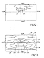
- the photometry produced by the zones 4B1 and 4B2 in cooperation with the filament 2 is illustrated on Fig.12 .
- the isolux curves are located above the horizontal plane passing through the optical axis and extend on either side of the vertical plane passing through this optical axis.
- the central curve L5 corresponds to a level of 0.25 lux, the curves L6a and L6b to 0.1 lux and the external curve L7 to 0.010 lux.
- Part of the DRL beam is provided by the cooperation of the filament 2 with the upper part 3 of the reflector.
- the photometry of this part is illustrated on Fig.10 .
- the isolux curves are located on either side of the vertical plane passing through the optical axis and on both sides of the horizontal plane, being, however, tighter below this horizontal plane and further apart above. the vertical direction.
- the narrowest central curve L8 corresponds to a level of 1 lux and the successive concentric curves L9, L10, L11, L12 and L13 correspond respectively to 0.75, 0.5, 0.250, 0.1 and 0.01 lux.
- the photometry of the DRL beam resulting from the composition of the photometries of Fig.10, 11 and 12 is illustrated on Fig.13 .
- the curves L14, L15, (L16a, L16b), L17, L18, L19 correspond to respective levels of 1 lux, 0.75 lux, 0.5 lux, 0.250 lux, 0.1 lux and 0.01. lux.
- the upper part 3 of the reflector or mirror is optimized to satisfy the fog function ( Fig.9 ).
- This upper part 3 is however designed so that, used with the filament 2 ( Fig.10 ), it completes the DRL beam without leading to values higher than the maximum allowed.
- the lower part 4 of the mirror which is in the shadow of the cup C for the filament 1, is optimized for the filament 2 in order to satisfy the DRL function according to the diagrams of the Fig. 11 and 12 .
- the upper part 3 of the mirror in the example considered, is optimized to fill both the photometry of the fog lamp ( Fig.9 ) but also part of the DRL function ( Fig.10 ) makes it possible to reduce the dimensions of the reflector R.
- the under voltage of the filament 2 allows an increase in the life of this filament.
- the invention can be achieved with any two-filament lamp, one of which is equipped with a mask or cup shading a part of the mirror.
- the glass G of the headlamp can be completely smooth, the desired photometry being provided by the different parts of the reflector R.
- the invention also relates to the motor vehicle equipped with at least one of the projectors described above.
Landscapes
- Engineering & Computer Science (AREA)
- Mechanical Engineering (AREA)
- General Engineering & Computer Science (AREA)
- Non-Portable Lighting Devices Or Systems Thereof (AREA)
- Lighting Device Outwards From Vehicle And Optical Signal (AREA)
Claims (9)
- Kraftfahrzeugscheinwerfer, mit: einer Lampe (L) mit zwei Glühfäden, nämlich einem ersten Glühfaden (1), der mit einer Blendwanne (C) versehen ist, die das Licht nur in einem vorgegebenen Winkelbereich passieren lässt, und einem zweiten Glühfaden (2) ohne Blendwanne; einem Reflektor (R) mit einem ersten Reflexionsbereich (3), der im Wesentlichen dazu vorgesehen ist, mit dem ersten Glühfaden (1) zusammenzuwirken und einen ersten Lichtbündeltyp zu erzeugen, und einem zweiten, im Schatten der Blendwanne (C) gelegenen Reflexionsbereich (4), der dazu vorgesehen ist, mit dem zweiten Glühfaden (2) zusammenzuwirken und gegebenenfalls mit dem ersten Reflexionsbereich einen zweiten Lichtbündeltyp zu bilden; und einer Reflektorabschlussscheibe (G), wobei der erste Glühfaden (1) mit Blendwanne der Nebellichtfunktion zugeordnet ist und der obere Teil (3) des Reflektors für diese Funktion ausgelegt ist,
dadurch gekennzeichnet, dass der zweite Glühfaden (2) der Lampe dazu vorgesehen ist, mit einer elektrischen Leistung betrieben zu werden, die gegenüber der des anderen Glühfadens (1) verringert ist und der Tagfahrlichtfunktion (DRL) zugeordnet ist, dass der Reflektor (R) so ausgelegt ist, dass mit dem zweiten Reflexionsbereich (4), der dem Glühfaden (2) mit geringerer Leistung zugeordnet ist, wenigstens ein Teil der DRL-Lichtverteilung gewährleistet wird, und dass der Scheinwerfer (P) eine Leuchtfläche hat, die mindestens der entspricht, die für die DRL-Funktion erforderlich ist, wobei der untere Teil (4) des Reflektors für die DRL-Funktion ausgelegt ist und zwei äußere Seitenbereiche (4B1, 4B2) aufweist, die dazu vorgesehen sind, das Licht nach oben und zur Mitte des DRL-Lichtbündels zu reflektieren. - Scheinwerfer nach Anspruch 1,
dadurch gekennzeichnet, dass der einer anderen Lichtfunktion als dem DRL zugeordnete Reflexionsbereich (3) des Reflektors derart ausgelegt ist, dass nicht Werte erreicht werden, die über dem Höchstwert liegen, der für das DRL zulässig ist. - Scheinwerfer nach Anspruch 1 oder 2, der mit einer Lampe mit zwei Glühfäden ausgestattet ist, die bei gleicher Spannung im Wesentlichen die gleiche Leistung haben,
dadurch gekennzeichnet, dass der der DRL-Funktion zugeordnete Glühfaden (2) mit Unterspannung betrieben wird. - Scheinwerfer nach Anspruch 3,
dadurch gekennzeichnet, dass er einen Schaltkreis (5) zum Verringern der Versorgungsspannung des der DRL-Funktion zugeordneten Glühfadens (2) umfasst. - Scheinwerfer nach Anspruch 1 oder 2,
dadurch gekennzeichnet, dass er eine Zweifaden-Glühlampe umfasst, die derart ausgelegt ist, dass der für die DRL-Funktion vorgesehene Glühfaden (2) bei der Nominalspannung, die an den anderen Glühfaden (1) angelegt wird, eine geringere Leistung hat. - Scheinwerfer nach einem der vorhergehenden Ansprüche,
dadurch gekennzeichnet, dass der Glühfaden (2) für die DRL-Funktion mit einer Leistung betrieben wird, die höchstens einem Drittel der Leistung des anderen Glühfadens (1) entspricht. - Scheinwerfer nach einem der vorhergehenden Ansprüche,
dadurch gekennzeichnet, dass der obere Teil (3) des Reflektors dazu vorgesehen ist, sowohl die Lichtverteilung des Nebellichts als auch einen Teil der DRL-Funktion zu bewirken, das heißt im Wesentlichen den Teil, der über der horizontalen Ebene liegt, wobei der untere Teil (4) des Reflektors zum Ausfüllen der übrigen Lichtverteilung der DRL-Funktion optimiert ist. - Scheinwerfer nach einem der vorhergehenden Ansprüche,
dadurch gekennzeichnet, dass die Abschlussscheibe (G) glatt ist. - Kraftfahrzeug,
dadurch gekennzeichnet, dass es mit wenigstens einem Scheinwerfer nach zumindest einem der vorhergehenden Ansprüche ausgestattet ist.
Applications Claiming Priority (2)
| Application Number | Priority Date | Filing Date | Title |
|---|---|---|---|
| FR0208936 | 2002-07-15 | ||
| FR0208936A FR2842282B1 (fr) | 2002-07-15 | 2002-07-15 | Projecteur de vehicule automobile avec lampe a deux filaments |
Publications (3)
| Publication Number | Publication Date |
|---|---|
| EP1382900A1 EP1382900A1 (de) | 2004-01-21 |
| EP1382900B1 EP1382900B1 (de) | 2005-10-19 |
| EP1382900B2 true EP1382900B2 (de) | 2009-10-21 |
Family
ID=29763882
Family Applications (1)
| Application Number | Title | Priority Date | Filing Date |
|---|---|---|---|
| EP03291723A Expired - Lifetime EP1382900B2 (de) | 2002-07-15 | 2003-07-10 | Kraftfahrzeugscheinwerfer mit einer Zweifadenlampe |
Country Status (5)
| Country | Link |
|---|---|
| EP (1) | EP1382900B2 (de) |
| AT (1) | ATE307319T1 (de) |
| DE (1) | DE60301921T3 (de) |
| ES (1) | ES2249694T5 (de) |
| FR (1) | FR2842282B1 (de) |
Families Citing this family (9)
| Publication number | Priority date | Publication date | Assignee | Title |
|---|---|---|---|---|
| FR2872564B1 (fr) | 2004-07-02 | 2007-03-16 | Valeo Vision Sa | Dispositif d'eclairage et/ou de signalisation pour vehicule automobile |
| EP1892461B1 (de) * | 2006-08-25 | 2013-03-13 | Hella KGaA Hueck & Co. | Scheinwerfer für Fahrzeuge |
| EP1903273B1 (de) * | 2006-09-19 | 2009-08-12 | Peugeot Citroen Automobiles S.A. | Kraftfahrzeugscheinwerfer mit zwei Funktionen |
| DE102006047837A1 (de) * | 2006-10-10 | 2008-04-17 | Volkswagen Ag | Scheinwerfer für ein Fahrzeug mit einer Tagfahrlichtanordnung |
| FR2911663B1 (fr) * | 2007-01-22 | 2009-04-17 | Valeo Vision Sa | Module optique multifonction de vehicule automobile |
| DE102007062136A1 (de) | 2007-12-21 | 2009-06-25 | Hella Kgaa Hueck & Co. | Scheinwerfer für Fahrzeuge |
| JP5368699B2 (ja) * | 2007-12-27 | 2013-12-18 | 株式会社小糸製作所 | 車両用前照灯 |
| CN102159875B (zh) | 2008-09-18 | 2014-04-30 | 皇家飞利浦电子股份有限公司 | 照明单元和车辆头灯 |
| FR2965325B1 (fr) * | 2010-09-29 | 2015-09-25 | Valeo Vision | Dispositif d'eclairage et de signalisation d'un vehicule automobile et procede de fonctionnement d'un tel dispositif |
Citations (3)
| Publication number | Priority date | Publication date | Assignee | Title |
|---|---|---|---|---|
| DE3533117A1 (de) † | 1985-09-17 | 1987-03-26 | Bosch Gmbh Robert | Scheinwerfer fuer das gemeinsame nebellicht und fernlicht von kraftfahrzeugen |
| EP0684420A1 (de) † | 1994-05-26 | 1995-11-29 | Valeo Vision | Scheinwerfer mit einer Zweifadenlampe zur Erzeugung eines Abblendlicht- und eines Fernlichtbündels |
| EP0791779A2 (de) † | 1996-02-23 | 1997-08-27 | Hella KG Hueck & Co. | Kraftfahrzeugscheinwerfer für Abblend- und Fernlicht und Lampe |
Family Cites Families (3)
| Publication number | Priority date | Publication date | Assignee | Title |
|---|---|---|---|---|
| FR2694373B1 (fr) | 1992-07-30 | 1994-11-04 | Valeo Vision | Projecteur de véhicule automobile comportant une lampe à deux filaments pour engendrer sélectivement un faisceau antibrouillard et un faisceau de route. |
| FR2782149B1 (fr) * | 1998-08-10 | 2001-04-13 | Valeo Vision | Projecteur de vehicule automobile pourvu d'une lampe a deux filaments et d'un miroir perfectionnes |
| DE19946297A1 (de) * | 1999-09-28 | 2001-04-12 | Philips Corp Intellectual Pty | Glühlampe |
-
2002
- 2002-07-15 FR FR0208936A patent/FR2842282B1/fr not_active Expired - Fee Related
-
2003
- 2003-07-10 ES ES03291723T patent/ES2249694T5/es not_active Expired - Lifetime
- 2003-07-10 AT AT03291723T patent/ATE307319T1/de not_active IP Right Cessation
- 2003-07-10 EP EP03291723A patent/EP1382900B2/de not_active Expired - Lifetime
- 2003-07-10 DE DE60301921T patent/DE60301921T3/de not_active Expired - Lifetime
Patent Citations (3)
| Publication number | Priority date | Publication date | Assignee | Title |
|---|---|---|---|---|
| DE3533117A1 (de) † | 1985-09-17 | 1987-03-26 | Bosch Gmbh Robert | Scheinwerfer fuer das gemeinsame nebellicht und fernlicht von kraftfahrzeugen |
| EP0684420A1 (de) † | 1994-05-26 | 1995-11-29 | Valeo Vision | Scheinwerfer mit einer Zweifadenlampe zur Erzeugung eines Abblendlicht- und eines Fernlichtbündels |
| EP0791779A2 (de) † | 1996-02-23 | 1997-08-27 | Hella KG Hueck & Co. | Kraftfahrzeugscheinwerfer für Abblend- und Fernlicht und Lampe |
Non-Patent Citations (3)
| Title |
|---|
| UNITED NATIONS: "Agreement concerning the adoption of uniform conditions of approval and reciprocal recognition of approval for motor vehicle equipment and parts", ECE REGULATION NO. 87, 30 March 1993 (1993-03-30), GENEVA † |
| UNITED NATIONS: "Agreement concerning the adoption of uniform technical prescriptions for wheeled vehicles, equipment and parts which can be fitted and/or be used on wheeled vehicles and the conditions for reciprocal recognition of approvals granted on the basis of these", ECE REGULATIONS 87, 3 December 2003 (2003-12-03), GENEVA † |
| UNITED NATIONS: "Agreement concerning the adoption of uniform technical prescriptions for wheeles vehicles, equipment and parts which can be fitted and/or be used on wheeled vehicles and the conditions for reciprocal recognition of approvals granted on the basis of these", ECE REGULATIONS NO. 48, 20 March 2001 (2001-03-20), GENEVA † |
Also Published As
| Publication number | Publication date |
|---|---|
| EP1382900A1 (de) | 2004-01-21 |
| ATE307319T1 (de) | 2005-11-15 |
| ES2249694T5 (es) | 2010-02-01 |
| DE60301921D1 (de) | 2006-03-02 |
| DE60301921T2 (de) | 2006-07-20 |
| EP1382900B1 (de) | 2005-10-19 |
| FR2842282B1 (fr) | 2004-12-17 |
| FR2842282A1 (fr) | 2004-01-16 |
| ES2249694T3 (es) | 2006-04-01 |
| DE60301921T3 (de) | 2010-03-11 |
Similar Documents
| Publication | Publication Date | Title |
|---|---|---|
| EP0581679B1 (de) | Kfz-Scheinwerfer mit einer Zweifaden-Glühlampe zur selektiven Erzeugung von Nebel- und Fernlicht | |
| FR2797680A1 (fr) | Phare pour vehicule | |
| EP0380396B1 (de) | Scheinwerfer für Kraftfahrzeuge mit einer einzigen Lichtquelle zum Erzeugen von zwei verschiedenen Lichtbündeln | |
| EP1433999B1 (de) | Kfz-Scheinwerfer mit einer querliegenden LIchtquelle | |
| EP0791780B1 (de) | Fahrzeugscheinwerfer mit einziger Lichtquelle für Ablendlicht und Fernlicht | |
| EP1431654A1 (de) | Kfz-Scheinwerfer der mindestens zwei Funktionen erfüllt | |
| FR2883066A1 (fr) | Projecteur lumineux a plusieurs fonctions pour vehicule automobile | |
| EP1382900B1 (de) | Kraftfahrzeugscheinwerfer mit einer Zweifadenlampe | |
| FR2755748A1 (fr) | Projecteur de vehicule automobile, comportant une lampe a decharge a occulteurs et un reflecteur multi-zones | |
| EP0684420B1 (de) | Scheinwerfer mit einer Zweifadenlampe zur Erzeugung eines Abblendlicht- und eines Fernlichtbündels | |
| FR2834681A1 (fr) | Dispositif de phare de type a faisceau jumele pour moto | |
| US6409369B1 (en) | Dual function headlight for a motor vehicle with a single light source and fixed optics | |
| EP1600689B1 (de) | Multifunktions-Scheinwerfer für Kraftfahrzeuge | |
| FR2609146A1 (fr) | Projecteur de vehicule automobile comportant un reflecteur parabolique a fond modifie | |
| EP1944542B1 (de) | Scheinwerfer mit zwei Funktionen für Kraftfahrzeug | |
| EP0258116B1 (de) | Scheinwerfer für Abblendlicht und Fernlicht mit zwei Transversalwendeln für Kraftfahrzeuge | |
| FR2810934A1 (fr) | Projecteur elliptique a modification de faisceau par mouvement d'elements optiques | |
| FR2760070A1 (fr) | Projecteur comportant une lampe a deux filaments pour engendrer un faisceau coupe et un faisceau non coupe | |
| EP1947380B1 (de) | Optisches Multifunktionsmodul für Kraftfahrzeug | |
| FR2808867A1 (fr) | Projecteur bi-fonction a source lumineuse unique et occulteur mobile pour vehicule automobile | |
| EP1870283B1 (de) | Scheinwerfereinheit mit drei Funktionen für Kraftfahrzeuge | |
| EP1241050B1 (de) | Anordnung für eine Beleuchtungsvorrichtung in einem Kraftfahrzeug | |
| EP0926431A1 (de) | Kraftfahrzeug- Scheinwerfer mit einem einzigen Reflektor und einer verstellbaren Lichtquelle zur Erzeugung von zwei verschiedenen Lichtbündeln | |
| FR2675443A1 (fr) | Phare de vehicules. | |
| FR2769687A1 (fr) | Ensemble de projecteurs gauche et droit de vehicule automobile, a proprietes photometriques ameliorees |
Legal Events
| Date | Code | Title | Description |
|---|---|---|---|
| PUAI | Public reference made under article 153(3) epc to a published international application that has entered the european phase |
Free format text: ORIGINAL CODE: 0009012 |
|
| AK | Designated contracting states |
Kind code of ref document: A1 Designated state(s): AT BE BG CH CY CZ DE DK EE ES FI FR GB GR HU IE IT LI LU MC NL PT RO SE SI SK TR |
|
| AX | Request for extension of the european patent |
Extension state: AL LT LV MK |
|
| 17P | Request for examination filed |
Effective date: 20040611 |
|
| 17Q | First examination report despatched |
Effective date: 20040730 |
|
| AKX | Designation fees paid |
Designated state(s): AT BE BG CH CY CZ DE DK EE ES FI FR GB GR HU IE IT LI LU MC NL PT RO SE SI SK TR |
|
| GRAP | Despatch of communication of intention to grant a patent |
Free format text: ORIGINAL CODE: EPIDOSNIGR1 |
|
| GRAS | Grant fee paid |
Free format text: ORIGINAL CODE: EPIDOSNIGR3 |
|
| GRAA | (expected) grant |
Free format text: ORIGINAL CODE: 0009210 |
|
| AK | Designated contracting states |
Kind code of ref document: B1 Designated state(s): AT BE BG CH CY CZ DE DK EE ES FI FR GB GR HU IE IT LI LU MC NL PT RO SE SI SK TR |
|
| PG25 | Lapsed in a contracting state [announced via postgrant information from national office to epo] |
Ref country code: SI Free format text: LAPSE BECAUSE OF FAILURE TO SUBMIT A TRANSLATION OF THE DESCRIPTION OR TO PAY THE FEE WITHIN THE PRESCRIBED TIME-LIMIT Effective date: 20051019 Ref country code: GB Free format text: LAPSE BECAUSE OF FAILURE TO SUBMIT A TRANSLATION OF THE DESCRIPTION OR TO PAY THE FEE WITHIN THE PRESCRIBED TIME-LIMIT Effective date: 20051019 Ref country code: FI Free format text: LAPSE BECAUSE OF FAILURE TO SUBMIT A TRANSLATION OF THE DESCRIPTION OR TO PAY THE FEE WITHIN THE PRESCRIBED TIME-LIMIT Effective date: 20051019 Ref country code: RO Free format text: LAPSE BECAUSE OF FAILURE TO SUBMIT A TRANSLATION OF THE DESCRIPTION OR TO PAY THE FEE WITHIN THE PRESCRIBED TIME-LIMIT Effective date: 20051019 Ref country code: SK Free format text: LAPSE BECAUSE OF FAILURE TO SUBMIT A TRANSLATION OF THE DESCRIPTION OR TO PAY THE FEE WITHIN THE PRESCRIBED TIME-LIMIT Effective date: 20051019 Ref country code: AT Free format text: LAPSE BECAUSE OF FAILURE TO SUBMIT A TRANSLATION OF THE DESCRIPTION OR TO PAY THE FEE WITHIN THE PRESCRIBED TIME-LIMIT Effective date: 20051019 Ref country code: CZ Free format text: LAPSE BECAUSE OF FAILURE TO SUBMIT A TRANSLATION OF THE DESCRIPTION OR TO PAY THE FEE WITHIN THE PRESCRIBED TIME-LIMIT Effective date: 20051019 Ref country code: IE Free format text: LAPSE BECAUSE OF FAILURE TO SUBMIT A TRANSLATION OF THE DESCRIPTION OR TO PAY THE FEE WITHIN THE PRESCRIBED TIME-LIMIT Effective date: 20051019 |
|
| REG | Reference to a national code |
Ref country code: GB Ref legal event code: FG4D Free format text: NOT ENGLISH |
|
| REG | Reference to a national code |
Ref country code: CH Ref legal event code: EP |
|
| REG | Reference to a national code |
Ref country code: IE Ref legal event code: FG4D Free format text: LANGUAGE OF EP DOCUMENT: FRENCH |
|
| PG25 | Lapsed in a contracting state [announced via postgrant information from national office to epo] |
Ref country code: SE Free format text: LAPSE BECAUSE OF FAILURE TO SUBMIT A TRANSLATION OF THE DESCRIPTION OR TO PAY THE FEE WITHIN THE PRESCRIBED TIME-LIMIT Effective date: 20060119 Ref country code: BG Free format text: LAPSE BECAUSE OF FAILURE TO SUBMIT A TRANSLATION OF THE DESCRIPTION OR TO PAY THE FEE WITHIN THE PRESCRIBED TIME-LIMIT Effective date: 20060119 Ref country code: GR Free format text: LAPSE BECAUSE OF FAILURE TO SUBMIT A TRANSLATION OF THE DESCRIPTION OR TO PAY THE FEE WITHIN THE PRESCRIBED TIME-LIMIT Effective date: 20060119 Ref country code: DK Free format text: LAPSE BECAUSE OF FAILURE TO SUBMIT A TRANSLATION OF THE DESCRIPTION OR TO PAY THE FEE WITHIN THE PRESCRIBED TIME-LIMIT Effective date: 20060119 |
|
| REF | Corresponds to: |
Ref document number: 60301921 Country of ref document: DE Date of ref document: 20060302 Kind code of ref document: P |
|
| PG25 | Lapsed in a contracting state [announced via postgrant information from national office to epo] |
Ref country code: PT Free format text: LAPSE BECAUSE OF FAILURE TO SUBMIT A TRANSLATION OF THE DESCRIPTION OR TO PAY THE FEE WITHIN THE PRESCRIBED TIME-LIMIT Effective date: 20060320 |
|
| REG | Reference to a national code |
Ref country code: ES Ref legal event code: FG2A Ref document number: 2249694 Country of ref document: ES Kind code of ref document: T3 |
|
| PG25 | Lapsed in a contracting state [announced via postgrant information from national office to epo] |
Ref country code: HU Free format text: LAPSE BECAUSE OF FAILURE TO SUBMIT A TRANSLATION OF THE DESCRIPTION OR TO PAY THE FEE WITHIN THE PRESCRIBED TIME-LIMIT Effective date: 20060420 |
|
| GBV | Gb: ep patent (uk) treated as always having been void in accordance with gb section 77(7)/1977 [no translation filed] |
Effective date: 20051019 |
|
| REG | Reference to a national code |
Ref country code: IE Ref legal event code: FD4D |
|
| PG25 | Lapsed in a contracting state [announced via postgrant information from national office to epo] |
Ref country code: MC Free format text: LAPSE BECAUSE OF NON-PAYMENT OF DUE FEES Effective date: 20060731 Ref country code: BE Free format text: LAPSE BECAUSE OF NON-PAYMENT OF DUE FEES Effective date: 20060731 |
|
| PLBI | Opposition filed |
Free format text: ORIGINAL CODE: 0009260 |
|
| PLAX | Notice of opposition and request to file observation + time limit sent |
Free format text: ORIGINAL CODE: EPIDOSNOBS2 |
|
| 26 | Opposition filed |
Opponent name: AUTOMOTIVE LIGHTING REUTLINGEN GMBH Effective date: 20060719 |
|
| NLR1 | Nl: opposition has been filed with the epo |
Opponent name: AUTOMOTIVE LIGHTING REUTLINGEN GMBH |
|
| PLAF | Information modified related to communication of a notice of opposition and request to file observations + time limit |
Free format text: ORIGINAL CODE: EPIDOSCOBS2 |
|
| PLBB | Reply of patent proprietor to notice(s) of opposition received |
Free format text: ORIGINAL CODE: EPIDOSNOBS3 |
|
| REG | Reference to a national code |
Ref country code: FR Ref legal event code: ST Effective date: 20070330 |
|
| PLAB | Opposition data, opponent's data or that of the opponent's representative modified |
Free format text: ORIGINAL CODE: 0009299OPPO |
|
| R26 | Opposition filed (corrected) |
Opponent name: AUTOMOTIVE LIGHTING REUTLINGEN GMBH Effective date: 20060719 |
|
| NLR1 | Nl: opposition has been filed with the epo |
Opponent name: AUTOMOTIVE LIGHTING REUTLINGEN GMBH |
|
| BERE | Be: lapsed |
Owner name: VALEO VISION Effective date: 20060731 |
|
| REG | Reference to a national code |
Ref country code: CH Ref legal event code: PL |
|
| PG25 | Lapsed in a contracting state [announced via postgrant information from national office to epo] |
Ref country code: LI Free format text: LAPSE BECAUSE OF NON-PAYMENT OF DUE FEES Effective date: 20070731 Ref country code: CH Free format text: LAPSE BECAUSE OF NON-PAYMENT OF DUE FEES Effective date: 20070731 Ref country code: FR Free format text: LAPSE BECAUSE OF NON-PAYMENT OF DUE FEES Effective date: 20060731 |
|
| PG25 | Lapsed in a contracting state [announced via postgrant information from national office to epo] |
Ref country code: EE Free format text: LAPSE BECAUSE OF FAILURE TO SUBMIT A TRANSLATION OF THE DESCRIPTION OR TO PAY THE FEE WITHIN THE PRESCRIBED TIME-LIMIT Effective date: 20051019 |
|
| PLAB | Opposition data, opponent's data or that of the opponent's representative modified |
Free format text: ORIGINAL CODE: 0009299OPPO |
|
| PG25 | Lapsed in a contracting state [announced via postgrant information from national office to epo] |
Ref country code: LU Free format text: LAPSE BECAUSE OF NON-PAYMENT OF DUE FEES Effective date: 20060710 Ref country code: TR Free format text: LAPSE BECAUSE OF FAILURE TO SUBMIT A TRANSLATION OF THE DESCRIPTION OR TO PAY THE FEE WITHIN THE PRESCRIBED TIME-LIMIT Effective date: 20051019 |
|
| PG25 | Lapsed in a contracting state [announced via postgrant information from national office to epo] |
Ref country code: CY Free format text: LAPSE BECAUSE OF FAILURE TO SUBMIT A TRANSLATION OF THE DESCRIPTION OR TO PAY THE FEE WITHIN THE PRESCRIBED TIME-LIMIT Effective date: 20051019 |
|
| PUAH | Patent maintained in amended form |
Free format text: ORIGINAL CODE: 0009272 |
|
| STAA | Information on the status of an ep patent application or granted ep patent |
Free format text: STATUS: PATENT MAINTAINED AS AMENDED |
|
| 27A | Patent maintained in amended form |
Effective date: 20091021 |
|
| AK | Designated contracting states |
Kind code of ref document: B2 Designated state(s): AT BE BG CH CY CZ DE DK EE ES FI FR GB GR HU IE IT LI LU MC NL PT RO SE SI SK TR |
|
| NLR2 | Nl: decision of opposition |
Effective date: 20091021 |
|
| NLR3 | Nl: receipt of modified translations in the netherlands language after an opposition procedure | ||
| REG | Reference to a national code |
Ref country code: ES Ref legal event code: DC2A Date of ref document: 20091116 Kind code of ref document: T5 |
|
| REG | Reference to a national code |
Ref country code: DE Ref legal event code: R079 Ref document number: 60301921 Country of ref document: DE Free format text: PREVIOUS MAIN CLASS: F21S0008100000 Ipc: F21S0043000000 |
|
| PGFP | Annual fee paid to national office [announced via postgrant information from national office to epo] |
Ref country code: NL Payment date: 20190617 Year of fee payment: 17 |
|
| PGFP | Annual fee paid to national office [announced via postgrant information from national office to epo] |
Ref country code: IT Payment date: 20190718 Year of fee payment: 17 Ref country code: DE Payment date: 20190711 Year of fee payment: 17 Ref country code: ES Payment date: 20190809 Year of fee payment: 17 |
|
| REG | Reference to a national code |
Ref country code: DE Ref legal event code: R119 Ref document number: 60301921 Country of ref document: DE |
|
| REG | Reference to a national code |
Ref country code: NL Ref legal event code: MM Effective date: 20200801 |
|
| PG25 | Lapsed in a contracting state [announced via postgrant information from national office to epo] |
Ref country code: NL Free format text: LAPSE BECAUSE OF NON-PAYMENT OF DUE FEES Effective date: 20200801 |
|
| PG25 | Lapsed in a contracting state [announced via postgrant information from national office to epo] |
Ref country code: DE Free format text: LAPSE BECAUSE OF NON-PAYMENT OF DUE FEES Effective date: 20210202 |
|
| REG | Reference to a national code |
Ref country code: ES Ref legal event code: FD2A Effective date: 20211201 |
|
| PG25 | Lapsed in a contracting state [announced via postgrant information from national office to epo] |
Ref country code: ES Free format text: LAPSE BECAUSE OF NON-PAYMENT OF DUE FEES Effective date: 20200711 |
|
| PG25 | Lapsed in a contracting state [announced via postgrant information from national office to epo] |
Ref country code: IT Free format text: LAPSE BECAUSE OF NON-PAYMENT OF DUE FEES Effective date: 20200710 |