EP1382920A2 - Vanne de détente - Google Patents
Vanne de détente Download PDFInfo
- Publication number
- EP1382920A2 EP1382920A2 EP03013781A EP03013781A EP1382920A2 EP 1382920 A2 EP1382920 A2 EP 1382920A2 EP 03013781 A EP03013781 A EP 03013781A EP 03013781 A EP03013781 A EP 03013781A EP 1382920 A2 EP1382920 A2 EP 1382920A2
- Authority
- EP
- European Patent Office
- Prior art keywords
- housing
- evaporator
- refrigerant
- expansion valve
- cassette unit
- Prior art date
- Legal status (The legal status is an assumption and is not a legal conclusion. Google has not performed a legal analysis and makes no representation as to the accuracy of the status listed.)
- Granted
Links
- 239000003507 refrigerant Substances 0.000 claims abstract description 54
- 238000005219 brazing Methods 0.000 claims description 5
- 238000006073 displacement reaction Methods 0.000 claims description 4
- 229910000838 Al alloy Inorganic materials 0.000 description 1
Images


Classifications
-
- F—MECHANICAL ENGINEERING; LIGHTING; HEATING; WEAPONS; BLASTING
- F25—REFRIGERATION OR COOLING; COMBINED HEATING AND REFRIGERATION SYSTEMS; HEAT PUMP SYSTEMS; MANUFACTURE OR STORAGE OF ICE; LIQUEFACTION SOLIDIFICATION OF GASES
- F25B—REFRIGERATION MACHINES, PLANTS OR SYSTEMS; COMBINED HEATING AND REFRIGERATION SYSTEMS; HEAT PUMP SYSTEMS
- F25B41/00—Fluid-circulation arrangements
- F25B41/30—Expansion means; Dispositions thereof
- F25B41/31—Expansion valves
- F25B41/33—Expansion valves with the valve member being actuated by the fluid pressure, e.g. by the pressure of the refrigerant
- F25B41/335—Expansion valves with the valve member being actuated by the fluid pressure, e.g. by the pressure of the refrigerant via diaphragms
-
- F—MECHANICAL ENGINEERING; LIGHTING; HEATING; WEAPONS; BLASTING
- F16—ENGINEERING ELEMENTS AND UNITS; GENERAL MEASURES FOR PRODUCING AND MAINTAINING EFFECTIVE FUNCTIONING OF MACHINES OR INSTALLATIONS; THERMAL INSULATION IN GENERAL
- F16K—VALVES; TAPS; COCKS; ACTUATING-FLOATS; DEVICES FOR VENTING OR AERATING
- F16K27/00—Construction of housing; Use of materials therefor
- F16K27/02—Construction of housing; Use of materials therefor of lift valves
- F16K27/0236—Diaphragm cut-off apparatus
-
- F—MECHANICAL ENGINEERING; LIGHTING; HEATING; WEAPONS; BLASTING
- F25—REFRIGERATION OR COOLING; COMBINED HEATING AND REFRIGERATION SYSTEMS; HEAT PUMP SYSTEMS; MANUFACTURE OR STORAGE OF ICE; LIQUEFACTION SOLIDIFICATION OF GASES
- F25B—REFRIGERATION MACHINES, PLANTS OR SYSTEMS; COMBINED HEATING AND REFRIGERATION SYSTEMS; HEAT PUMP SYSTEMS
- F25B39/00—Evaporators; Condensers
- F25B39/02—Evaporators
-
- F—MECHANICAL ENGINEERING; LIGHTING; HEATING; WEAPONS; BLASTING
- F25—REFRIGERATION OR COOLING; COMBINED HEATING AND REFRIGERATION SYSTEMS; HEAT PUMP SYSTEMS; MANUFACTURE OR STORAGE OF ICE; LIQUEFACTION SOLIDIFICATION OF GASES
- F25B—REFRIGERATION MACHINES, PLANTS OR SYSTEMS; COMBINED HEATING AND REFRIGERATION SYSTEMS; HEAT PUMP SYSTEMS
- F25B2341/00—Details of ejectors not being used as compression device; Details of flow restrictors or expansion valves
- F25B2341/06—Details of flow restrictors or expansion valves
- F25B2341/068—Expansion valves combined with a sensor
- F25B2341/0683—Expansion valves combined with a sensor the sensor is disposed in the suction line and influenced by the temperature or the pressure of the suction gas
-
- F—MECHANICAL ENGINEERING; LIGHTING; HEATING; WEAPONS; BLASTING
- F25—REFRIGERATION OR COOLING; COMBINED HEATING AND REFRIGERATION SYSTEMS; HEAT PUMP SYSTEMS; MANUFACTURE OR STORAGE OF ICE; LIQUEFACTION SOLIDIFICATION OF GASES
- F25B—REFRIGERATION MACHINES, PLANTS OR SYSTEMS; COMBINED HEATING AND REFRIGERATION SYSTEMS; HEAT PUMP SYSTEMS
- F25B2500/00—Problems to be solved
- F25B2500/18—Optimization, e.g. high integration of refrigeration components
Definitions
- the present invention relates to an expansion valve used in an air conditioner of a car or the like, and especially relates to an expansion valve having its main components constituting a cassette unit which can be accommodated in a housing to complete the functions of the expansion valve.
- the expansion valve used in an air conditioner of a car or the like is generally composed of a valve body formed of an aluminum alloy or the like, a valve seat disposed within the valve body, a valve member disposed so as to come into contact with the valve seat, and a drive means for driving the valve member.
- the valve body is provided with a refrigerant entrance through which the refrigerant coming from a compressor enters, a refrigerant exit through which the refrigerant traveling toward an evaporator exits, and a valve chamber disposed between the entrance and the exit.
- the valve body is further equippedwith a refrigerant passage through which refrigerant returning to the compressor from the evaporator travels.
- the drive means of the valve member includes a diaphragm, and the displacement of the diaphragm is transmitted via a shaft to the valve member.
- the conventional expansion valve explained above has been provided as a completed component that constitutes a main portion of the air conditioner.
- the present invention provides a cassette unit containing the main components of the expansion valve, and by inserting (assembling) this cassette unit to a separately prepared housing via seal members, the present invention completes the functions of the expansion valve.
- the housing is either adjacent to or formed integrally with the evaporator, so as to cut down the overall size and weight of the air conditioner.
- the present expansion valve is composed of a cassette unit equipped with the main components of the expansion valve, and a housing having refrigerant paths and accommodating the cassette unit via seal members.
- the cassette unit comprises a pipe member, a refrigerant path disposed to the pipe member, a flange member connected to the end of the pipe member, a lid member covering the flange member, a diaphragm disposedbetween the flange member and the lid member, and a valve mechanism that transfers the displacement of the diaphragm to the valve member so as to control the flow of refrigerant.
- the housing is formed integrally with the evaporator of the air conditioner.
- the housing is joined to the evaporator through a brazing means, and the expansion valve is further equipped with a pipe that connects the housing to the evaporator.
- the housing can be disposed within a refrigerant tank of the evaporator.
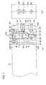
- FIG. 1 shows a cross-sectional view (a) and a right side view (b) illustrating the mounting structure of the cassette-type expansion valve according to the present invention.
- an evaporator 10 of the air conditioner is positioned at the inner side of a dashboard near the driver's seat of the car.
- the evaporator 10 comprises an entry port 12 through which high-pressure refrigerant enters and an exit port 14 through which refrigerant having completed heat change exits, and the evaporator 10 is covered with a division wall 16.
- the housing 200 is either mounted to this division wall 16 or formed as a portion of the extended division wall itself.
- the housing 200 comprises an inlet 210 for the refrigerant entering the housing from a compressor, an outlet 220 for sending the refrigerant having a controlled flow toward the entrance port 12 of the evaporator, and a return path 230 that connects to the exit port 14 of the evaporator.
- the housing 200 further comprises a mounting hole 240 with steps formed in the direction orthogonal to the above-mentioned refrigerant paths, into which is inserted a cassette unit 100 of the expansion valve.
- the cassette unit 100 comprises a pipe member 110, and the pipe member 110 is equipped with an entrance hole 112 for the refrigerant, an exit hole 114 for the refrigerant traveling toward the evaporator, and a through-hole 116 for the refrigerant returning from the evaporator.
- the upper end of the pipe member 110 is connected to a flange member 120, and the flange member 120 is covered with a lid member 130.
- a diaphragm is disposed between the flange member 120 and the lid member 130, and the displacement of the diaphragm is transmitted to the valve member via a valve shaft.
- the movement of the valve member controls the flow of the refrigerant flowing in through the entrance hole 112, and the controlled flow of refrigerant is supplied through the exit hole 114 toward the entrance port 12 of the evaporator.
- the refrigerant returning from the exit port 14 of the evaporator passes through the through-hole 116, where the pressure and the temperature information of the refrigerant are transmitted to the diaphragm.
- the functions of the expansion valve mentioned above are the same as those of an ordinary expansion valve.
- the cassette unit 100 is sealed to the mounting hole 240 of the housing via seal rings 160, 162, 164 and so on.
- the upper portion of the lid member 130 is fixedby an O-ring 140 and covered with a rubber cap 150 that prevents foreign matter from entering the valve.
- a flange 50 fixed thereto via a bolt 60.
- This flange 50 comprises a path 52 that communicates with the outlet of the compressor and a path 54 that communicates with the inlet of the compressor, and is mounted to the housing 200 via seal rings 70 and 72.
- the cassette unit 100 of the expansion valve is disposed adjacent to the evaporator 10, the overall size and weight of the air conditioner can be reduced. Thus, less mounting space is required.
- FIG. 2 is a cross-sectional view showing another embodiment of the present invention.
- a housing 300 is disposed so as to connect to a refrigerant entrance port 12 and a refrigerant exit port 14 that are formed on a division wall 16 of the evaporator 10.
- the housing 300 comprises a refrigerant inlet 310 for the refrigerant entering the housing from a compressor, and an outlet 320 for sending the refrigerant having a controlled flow toward the entrance port 12 of the evaporator, the connection between the entrance port 12 being formed to a pipe portion 322.
- the housing further comprises a refrigerant returnpath 330 connected to the exit port 14 of the evaporator, and the connection with the exit port 14 is formed to a pipe portion 332. Both pipe portions 322 and 332 are joined to the division wall 16 via brazing means W 1 .
- the housing 300 further comprises a mounting hole 340 with steps formed in the direction orthogonal to the above-mentioned refrigerant paths, into which is inserted the cassette unit 100 of the expansion valve.
- the structure of the cassette unit 100 is the same as that explained in the embodiment of FIG. 1, so the explanation thereof is omitted.
- a flange 50 fixed thereto via a bolt 60.
- This flange 50 comprises a path 52 that communicates with the outlet of the compressor and a path 54 that communicates with the inlet of the compressor.
- the mounting structure of the cassette unit to the housing 300 is the same as that explained in the embodiment of FIG. 1, so the explanation thereof is omitted.
- FIG. 3 is a cross-sectional view showing another embodiment of the present invention.
- a housing 400 is disposed so as to connect to a refrigerant entrance port 12 and a refrigerant exit port 14 that are formed on a division wall 16 of the evaporator 10.
- the housing 400 comprises a refrigerant inlet 410 for the refrigerant entering the housing from a compressor, and an outlet 420 for sending the refrigerant having a controlled flow toward the entrance port 12 of the evaporator.
- the housing 400 is connected to the entrance port 12 via a pipe 450.
- the housing further comprises a refrigerant return path 430 that connects to the exit port 14 of the evaporator, and the housing is connected to the exit port 14 via a pipe 460. Both pipes 450 and 460 are joined with the division wall 16 and the housing 400 via brazing means W 1 .
- the housing 400 further comprises a mounting hole 440 with steps formed in the direction orthogonal to the above-mentioned refrigerant paths, which accommodates the cassette unit 100 of the expansion valve.
- the structure of the cassette unit 100 is the same as that explained with reference to FIG. 1, so the explanation thereof is omitted.
- a flange 50 fixed thereto via a bolt 60.
- This flange 50 comprises a path 52 that communicates with the outlet of the compressor and a path 54 that communicates with the inlet of the compressor.
- the mounting structure of the cassette unit to the housing 400 is the same as that explained in the embodiment of FIG. 1, so the explanation thereof is omitted.
- FIG. 4 is a cross-sectional view showing another embodiment of the present invention.
- a housing 500 is disposed so as to connect to a refrigerant entrance port 12 and a refrigerant exit port 14 that are formed on a division wall 16 of the evaporator 10.
- the housing 500 comprises a refrigerant inlet 510 for the refrigerant entering the housing from a compressor, and an outlet 520 for sending the refrigerant having a controlled flow toward the entrance port 12 of the evaporator.
- the housing 500 is connected to the entrance port 12 via a pipe 550.
- the housing further comprises a refrigerant return path 530 that connects to the exit port 14 of the evaporator, and the housing is connected to the exit port 14 via a pipe 560. Both pipes 550 and 560 are joined with the division wall 16 and the housing 500 via brazing means W 1 .
- the housing 500 further comprises a mounting hole 540 with steps formed in the direction orthogonal to the above-mentioned refrigerant paths, which accommodates the cassette unit 100 of the expansion valve.
- the structure of the cassette unit 100 is the same as that explained with reference to FIG. 1, so the explanation thereof is omitted.
- a flange 50 fixed thereto via a bolt 60.
- This flange 50 comprises a path 52 that communicates with the outlet of the compressor and a path 54 that communicates with the inlet of the compressor.
- the mounting structure of the cassette unit to the housing 500 is the same as that explained in the embodiment of FIG. 1, so the explanation thereof is omitted.
- the evaporator 10 and the housing 500 are communicated via long pipes 550 and 560, so the housing 500 constituting the expansion valve can be disposed inside an engine room of the car.
- FIG. 5 is a cross-sectional view showing yet another embodiment of the present invention.
- the evaporator 10 comprises an inlet tank 12a that is connected to an entrance port 12 of the refrigerant, an outlet tank 14a that is connected to an exit port 14 of the refrigerant, and a plate 13 that divides the two tanks .
- a pipe-shaped housing 40 with steps is formed to the inner portion of the evaporator 10, for accommodating the cassette unit 100 of the expansion valve.
- the structure of the cassette unit 100 is the same as that explained in the embodiment of FIG. 1, so the explanation thereof is omitted.
- Two pipes 42 and 44 pass through the division wall 16 of the evaporator 10 and connect to the housing 40.
- the pipe 42 is connected to the discharge side of the compressor and the pipe 44 is connected to the inlet side of the compressor.
- the present expansion valve is composed of a cassette unit including a valve mechanism that constitutes the main portion of the expansion valve and a drive unit of the valve mechanism, and a housing having refrigerant paths formed as a separate structure from the cassette unit.
- the expansion valve is completed by inserting the cassette unit to the housing and providing a seal structure.
- the freedom of design of the expansion valve is improved, and for example, the housing can be disposed adjacent to the evaporator or even within the evaporator. Moreover, the number of components constituting the expansion valve is reduced, and the overall size and weight of the air conditioner can be minimized.
Landscapes
- Engineering & Computer Science (AREA)
- General Engineering & Computer Science (AREA)
- Mechanical Engineering (AREA)
- Physics & Mathematics (AREA)
- Thermal Sciences (AREA)
- Fluid Mechanics (AREA)
- Air-Conditioning For Vehicles (AREA)
- Temperature-Responsive Valves (AREA)
- Valve Housings (AREA)
Applications Claiming Priority (2)
| Application Number | Priority Date | Filing Date | Title |
|---|---|---|---|
| JP2002208217 | 2002-07-17 | ||
| JP2002208217A JP2004053060A (ja) | 2002-07-17 | 2002-07-17 | 膨張弁 |
Publications (3)
| Publication Number | Publication Date |
|---|---|
| EP1382920A2 true EP1382920A2 (fr) | 2004-01-21 |
| EP1382920A3 EP1382920A3 (fr) | 2004-04-21 |
| EP1382920B1 EP1382920B1 (fr) | 2009-05-27 |
Family
ID=29774633
Family Applications (1)
| Application Number | Title | Priority Date | Filing Date |
|---|---|---|---|
| EP03013781A Expired - Lifetime EP1382920B1 (fr) | 2002-07-17 | 2003-06-18 | Vanne de détente |
Country Status (5)
| Country | Link |
|---|---|
| US (1) | US6942160B2 (fr) |
| EP (1) | EP1382920B1 (fr) |
| JP (1) | JP2004053060A (fr) |
| KR (1) | KR20040008075A (fr) |
| DE (1) | DE60327728D1 (fr) |
Cited By (3)
| Publication number | Priority date | Publication date | Assignee | Title |
|---|---|---|---|---|
| CN103712383A (zh) * | 2012-09-29 | 2014-04-09 | 杭州三花研究院有限公司 | 换热器与膨胀阀的集成组件及其制造方法 |
| CN104296422A (zh) * | 2013-07-19 | 2015-01-21 | 杭州三花研究院有限公司 | 换热器集成组件 |
| US10066878B2 (en) | 2012-09-29 | 2018-09-04 | Zhejiang Sanhua Automotive Components Co., Ltd. | Heat exchanger integrated assembly and manufacturing method thereof |
Families Citing this family (10)
| Publication number | Priority date | Publication date | Assignee | Title |
|---|---|---|---|---|
| US7089761B2 (en) * | 2004-01-08 | 2006-08-15 | Parker-Hannifin Corporation | Expansion valve with mounting bracket |
| JP4466448B2 (ja) * | 2005-04-18 | 2010-05-26 | 株式会社デンソー | 車両用空調装置 |
| JP2008175417A (ja) * | 2007-01-16 | 2008-07-31 | Calsonic Kansei Corp | 膨張弁 |
| DE102010004294A1 (de) * | 2010-01-11 | 2011-07-14 | Valeo Klimasysteme GmbH, 96476 | Kopplungseinheit zur Verbindung von Kältemittelleitungen eines Kältemittelkreislaufs |
| US9398722B1 (en) * | 2013-09-03 | 2016-07-19 | Mainstream Engineering Corporation | Cold plate with insertable integrated thermostatic expansion device and sensing element |
| JP6446636B2 (ja) * | 2015-02-06 | 2019-01-09 | 株式会社テージーケー | 膨張弁およびその配管取付構造 |
| US20170234456A1 (en) * | 2016-02-11 | 2017-08-17 | Dunan Microstaq, Inc. | Heat exchanger with expansion valve body formed on inlet header thereof |
| JP6897478B2 (ja) * | 2017-10-11 | 2021-06-30 | 株式会社デンソー | 熱交換器 |
| JP2020139680A (ja) * | 2019-02-28 | 2020-09-03 | 株式会社デンソー | 冷凍サイクル装置 |
| US11879676B2 (en) | 2021-07-30 | 2024-01-23 | Danfoss A/S | Thermal expansion valve for a heat exchanger and heat exchanger with a thermal expansion valve |
Citations (4)
| Publication number | Priority date | Publication date | Assignee | Title |
|---|---|---|---|---|
| US3855836A (en) | 1973-01-24 | 1974-12-24 | Hitachi Ltd | Device for controlling coolant pressure in evaporator |
| EP0691517A1 (fr) | 1994-06-29 | 1996-01-10 | TGK CO., Ltd. | Vanne de détente unitaire |
| JPH08152232A (ja) | 1994-11-25 | 1996-06-11 | Zexel Corp | 膨張弁 |
| US5732570A (en) | 1995-11-24 | 1998-03-31 | Denso Corporation | Thermal expansion valve and air conditioning apparatus using the same |
Family Cites Families (23)
| Publication number | Priority date | Publication date | Assignee | Title |
|---|---|---|---|---|
| GB203391A (en) * | 1922-06-06 | 1923-09-06 | Max Schloetter | Improvements in and relating to printing and stamping rollers |
| US3858406A (en) * | 1972-09-06 | 1975-01-07 | Nissan Motor | Refrigerant evaporator for air conditioner |
| DE2946466C2 (de) * | 1979-11-17 | 1985-02-21 | Arnold 7312 Kirchheim Müller | Heizeinrichtung mit einem Kältemittelkreislauf |
| GB2073391A (en) * | 1980-04-03 | 1981-10-14 | United Gas Industries Ltd | Refrigeration installation |
| US4468054A (en) * | 1982-11-03 | 1984-08-28 | The Singer Company | Flange mounted thermostatic expansion valve |
| US4542852A (en) * | 1984-03-05 | 1985-09-24 | The Singer Company | Vibration damping device for thermostatic expansion valves |
| US5169178A (en) * | 1990-06-14 | 1992-12-08 | Modine Manufacturing Co. | Fitting for use in a heat exchange system |
| FR2668242B1 (fr) * | 1990-10-17 | 1993-01-22 | Valeo | Bride pour le raccordement des tubulures d'entree et de sortie d'un evaporateur. |
| US5269459A (en) * | 1991-10-17 | 1993-12-14 | Eaton Corporation | Thermally responsive expansion valve |
| US5308125A (en) * | 1993-02-08 | 1994-05-03 | General Motors Corporation | Sealed connector for automotive A/C system |
| EP0659600B1 (fr) * | 1993-12-22 | 1999-08-04 | Calsonic Corporation | Dispositif des tuyaux d'une installation de climatisation sur un véhicule automobile |
| JP3413937B2 (ja) * | 1994-03-28 | 2003-06-09 | 株式会社デンソー | 配管接続装置 |
| JP3208992B2 (ja) * | 1994-06-07 | 2001-09-17 | 株式会社デンソー | 車両用空調装置 |
| JPH0882457A (ja) * | 1994-09-09 | 1996-03-26 | Zexel Corp | 積層型熱交換器 |
| US5467611A (en) * | 1994-11-07 | 1995-11-21 | General Motors Corporation | Two plate TXV block connector for automotive A/C system with common bolts and independently attachable sides |
| JP3794100B2 (ja) * | 1996-07-01 | 2006-07-05 | 株式会社デンソー | 電磁弁一体型膨張弁 |
| JP3882299B2 (ja) * | 1997-12-22 | 2007-02-14 | 株式会社デンソー | 電磁弁一体型膨張弁 |
| JPH11325660A (ja) * | 1998-03-18 | 1999-11-26 | Fujikoki Corp | 膨張弁 |
| US6062484A (en) * | 1998-05-20 | 2000-05-16 | Eaton Corporation | Modular thermal expansion valve and cartridge therefor |
| US6189333B1 (en) * | 1999-07-26 | 2001-02-20 | Delphi Technologies, Inc. | Refrigerant filter for use in an automotive air conditioning system |
| JP2001116401A (ja) * | 1999-10-15 | 2001-04-27 | Tgk Co Ltd | 膨張弁 |
| US6375086B1 (en) * | 2001-07-30 | 2002-04-23 | Eaton Corporation | Modulating refrigerant flow through a motorized expansion valve |
| US6615599B1 (en) * | 2002-06-26 | 2003-09-09 | Delphi Technologies Inc. | Thermostatic expansion valve and air conditioning system for low refrigerant charge |
-
2002
- 2002-07-17 JP JP2002208217A patent/JP2004053060A/ja active Pending
-
2003
- 2003-06-18 DE DE60327728T patent/DE60327728D1/de not_active Expired - Lifetime
- 2003-06-18 EP EP03013781A patent/EP1382920B1/fr not_active Expired - Lifetime
- 2003-06-23 US US10/600,702 patent/US6942160B2/en not_active Expired - Fee Related
- 2003-06-26 KR KR1020030042214A patent/KR20040008075A/ko not_active Withdrawn
Patent Citations (4)
| Publication number | Priority date | Publication date | Assignee | Title |
|---|---|---|---|---|
| US3855836A (en) | 1973-01-24 | 1974-12-24 | Hitachi Ltd | Device for controlling coolant pressure in evaporator |
| EP0691517A1 (fr) | 1994-06-29 | 1996-01-10 | TGK CO., Ltd. | Vanne de détente unitaire |
| JPH08152232A (ja) | 1994-11-25 | 1996-06-11 | Zexel Corp | 膨張弁 |
| US5732570A (en) | 1995-11-24 | 1998-03-31 | Denso Corporation | Thermal expansion valve and air conditioning apparatus using the same |
Cited By (3)
| Publication number | Priority date | Publication date | Assignee | Title |
|---|---|---|---|---|
| CN103712383A (zh) * | 2012-09-29 | 2014-04-09 | 杭州三花研究院有限公司 | 换热器与膨胀阀的集成组件及其制造方法 |
| US10066878B2 (en) | 2012-09-29 | 2018-09-04 | Zhejiang Sanhua Automotive Components Co., Ltd. | Heat exchanger integrated assembly and manufacturing method thereof |
| CN104296422A (zh) * | 2013-07-19 | 2015-01-21 | 杭州三花研究院有限公司 | 换热器集成组件 |
Also Published As
| Publication number | Publication date |
|---|---|
| JP2004053060A (ja) | 2004-02-19 |
| EP1382920B1 (fr) | 2009-05-27 |
| DE60327728D1 (de) | 2009-07-09 |
| EP1382920A3 (fr) | 2004-04-21 |
| US6942160B2 (en) | 2005-09-13 |
| US20040011078A1 (en) | 2004-01-22 |
| KR20040008075A (ko) | 2004-01-28 |
Similar Documents
| Publication | Publication Date | Title |
|---|---|---|
| EP1382920A2 (fr) | Vanne de détente | |
| US6185959B1 (en) | Refrigerant system components with cartridge type thermal expansion valve and method of making same | |
| US5724817A (en) | Laminated heat exchanger | |
| EP1384962B1 (fr) | Vanne de détente | |
| EP1130345B1 (fr) | Vanne d'expansion | |
| US6935573B2 (en) | Expansion valve | |
| EP1262699B1 (fr) | Soupape de détente | |
| JP2001201212A (ja) | 温度膨張弁 | |
| EP1262698B1 (fr) | Soupape de détente | |
| JP2001199230A (ja) | 温度膨張弁 | |
| JP2017211137A (ja) | 電気式膨張弁 | |
| US6606879B1 (en) | Accumulator assembly having a reversing valve and a heat pump system thereof | |
| US6776351B2 (en) | Expansion valve | |
| JP4462813B2 (ja) | 膨張弁 | |
| JP4146255B2 (ja) | 膨張弁 | |
| JP2004050893A (ja) | 膨張弁 | |
| JP2008056062A (ja) | 蒸気圧縮式冷凍サイクル |
Legal Events
| Date | Code | Title | Description |
|---|---|---|---|
| PUAI | Public reference made under article 153(3) epc to a published international application that has entered the european phase |
Free format text: ORIGINAL CODE: 0009012 |
|
| AK | Designated contracting states |
Kind code of ref document: A2 Designated state(s): AT BE BG CH CY CZ DE DK EE ES FI FR GB GR HU IE IT LI LU MC NL PT RO SE SI SK TR |
|
| AX | Request for extension of the european patent |
Extension state: AL LT LV MK |
|
| PUAL | Search report despatched |
Free format text: ORIGINAL CODE: 0009013 |
|
| AK | Designated contracting states |
Kind code of ref document: A3 Designated state(s): AT BE BG CH CY CZ DE DK EE ES FI FR GB GR HU IE IT LI LU MC NL PT RO SE SI SK TR |
|
| AX | Request for extension of the european patent |
Extension state: AL LT LV MK |
|
| 17P | Request for examination filed |
Effective date: 20040828 |
|
| AKX | Designation fees paid |
Designated state(s): DE FR GB IT |
|
| 17Q | First examination report despatched |
Effective date: 20070626 |
|
| GRAP | Despatch of communication of intention to grant a patent |
Free format text: ORIGINAL CODE: EPIDOSNIGR1 |
|
| GRAS | Grant fee paid |
Free format text: ORIGINAL CODE: EPIDOSNIGR3 |
|
| GRAA | (expected) grant |
Free format text: ORIGINAL CODE: 0009210 |
|
| AK | Designated contracting states |
Kind code of ref document: B1 Designated state(s): DE FR GB IT |
|
| REG | Reference to a national code |
Ref country code: GB Ref legal event code: FG4D |
|
| REF | Corresponds to: |
Ref document number: 60327728 Country of ref document: DE Date of ref document: 20090709 Kind code of ref document: P |
|
| PLBE | No opposition filed within time limit |
Free format text: ORIGINAL CODE: 0009261 |
|
| STAA | Information on the status of an ep patent application or granted ep patent |
Free format text: STATUS: NO OPPOSITION FILED WITHIN TIME LIMIT |
|
| 26N | No opposition filed |
Effective date: 20100302 |
|
| PGFP | Annual fee paid to national office [announced via postgrant information from national office to epo] |
Ref country code: FR Payment date: 20100709 Year of fee payment: 8 |
|
| PGFP | Annual fee paid to national office [announced via postgrant information from national office to epo] |
Ref country code: DE Payment date: 20100616 Year of fee payment: 8 Ref country code: GB Payment date: 20100616 Year of fee payment: 8 |
|
| PG25 | Lapsed in a contracting state [announced via postgrant information from national office to epo] |
Ref country code: IT Free format text: LAPSE BECAUSE OF FAILURE TO SUBMIT A TRANSLATION OF THE DESCRIPTION OR TO PAY THE FEE WITHIN THE PRESCRIBED TIME-LIMIT Effective date: 20090527 |
|
| GBPC | Gb: european patent ceased through non-payment of renewal fee |
Effective date: 20110618 |
|
| REG | Reference to a national code |
Ref country code: FR Ref legal event code: ST Effective date: 20120229 |
|
| REG | Reference to a national code |
Ref country code: DE Ref legal event code: R119 Ref document number: 60327728 Country of ref document: DE Effective date: 20120103 |
|
| PG25 | Lapsed in a contracting state [announced via postgrant information from national office to epo] |
Ref country code: DE Free format text: LAPSE BECAUSE OF NON-PAYMENT OF DUE FEES Effective date: 20120103 Ref country code: FR Free format text: LAPSE BECAUSE OF NON-PAYMENT OF DUE FEES Effective date: 20110630 |
|
| PG25 | Lapsed in a contracting state [announced via postgrant information from national office to epo] |
Ref country code: GB Free format text: LAPSE BECAUSE OF NON-PAYMENT OF DUE FEES Effective date: 20110618 |