EP1382931A1 - Sicherheitsschloss für Pistolenholster - Google Patents
Sicherheitsschloss für Pistolenholster Download PDFInfo
- Publication number
- EP1382931A1 EP1382931A1 EP03425477A EP03425477A EP1382931A1 EP 1382931 A1 EP1382931 A1 EP 1382931A1 EP 03425477 A EP03425477 A EP 03425477A EP 03425477 A EP03425477 A EP 03425477A EP 1382931 A1 EP1382931 A1 EP 1382931A1
- Authority
- EP
- European Patent Office
- Prior art keywords
- arm
- button
- push
- holster
- seating
- Prior art date
- Legal status (The legal status is an assumption and is not a legal conclusion. Google has not performed a legal analysis and makes no representation as to the accuracy of the status listed.)
- Granted
Links
- 238000006243 chemical reaction Methods 0.000 claims description 4
- 238000006073 displacement reaction Methods 0.000 description 3
- 230000007123 defense Effects 0.000 description 1
- 230000001419 dependent effect Effects 0.000 description 1
- 230000000994 depressogenic effect Effects 0.000 description 1
- 230000000694 effects Effects 0.000 description 1
- 238000000605 extraction Methods 0.000 description 1
- 230000037081 physical activity Effects 0.000 description 1
Images



Classifications
-
- F—MECHANICAL ENGINEERING; LIGHTING; HEATING; WEAPONS; BLASTING
- F41—WEAPONS
- F41C—SMALLARMS, e.g. PISTOLS, RIFLES; ACCESSORIES THEREFOR
- F41C33/00—Means for wearing or carrying smallarms
- F41C33/02—Holsters, i.e. cases for pistols having means for being carried or worn, e.g. at the belt or under the arm
- F41C33/0209—Pouch or pocket like containers for small arms covering all or most of the small arm
- F41C33/0227—Pouch or pocket like containers for small arms covering all or most of the small arm having a strap or other restraining element only covering the hammer or a part of the upper part of the small arm
-
- F—MECHANICAL ENGINEERING; LIGHTING; HEATING; WEAPONS; BLASTING
- F41—WEAPONS
- F41C—SMALLARMS, e.g. PISTOLS, RIFLES; ACCESSORIES THEREFOR
- F41C33/00—Means for wearing or carrying smallarms
- F41C33/02—Holsters, i.e. cases for pistols having means for being carried or worn, e.g. at the belt or under the arm
- F41C33/0263—Holsters, i.e. cases for pistols having means for being carried or worn, e.g. at the belt or under the arm having a locking system for preventing unauthorized or accidental removal of the small arm from the holster
-
- F—MECHANICAL ENGINEERING; LIGHTING; HEATING; WEAPONS; BLASTING
- F41—WEAPONS
- F41C—SMALLARMS, e.g. PISTOLS, RIFLES; ACCESSORIES THEREFOR
- F41C33/00—Means for wearing or carrying smallarms
- F41C33/02—Holsters, i.e. cases for pistols having means for being carried or worn, e.g. at the belt or under the arm
- F41C33/04—Special attachments therefor
Definitions
- the present invention relates to a safety lock for holsters. More precisely, the invention relates to a safety lock capable of preventing the accidental or non-authorized manipulation of the device that disengages the pistol from the holster.
- holsters for pistols especially those used by the police and personnel concerned with the defense of persons and goods, 'have to be designed in such a way as to firmly retain the weapon, and this not only during the normal movements of the user, but also on the occasion of more intensive physical activities, scuffles and the like, while yet enabling the user to pull it out easily and quickly in case of need.
- Particularly convenient among the various configurations that have been proposed has been found to be the one that envisages the use of a mobile strap attached to the mouth of the holster and intended to fit around the butt of the weapon when it is in position within the holster.
- a snap connection device locks the strap in this position and prevents the weapon from slipping out of the holster.
- it is sufficient to press a button integral to the strap to release the snap connection device it is sufficient to press a button integral to the strap to release the snap connection device, overcoming an elastic reaction, and to permit an angular displacement of the strap to free the weapon.
- the button by means of which the strap is released and allowed to rotate has been equipped with a lock that prevents it from moving and must necessarily be deactivated before the button can be operated.
- the extraction of the weapon becomes more laborious and effectively calls for the execution of two distinct and successive movements of the hand. This can involve difficulty and delay in pulling out the weapon and create a situation of danger for the user.
- the object of the present invention is to provide a safety lock device for a pistol holster that will have the same efficacy as the known devices, but without being associated with the drawbacks set out above.
- a particular object of the present invention is to provide a locking device of the aforementioned type in which the release of the button and its actual depression are obtained by acting directly on the button itself.
- the reference number 1 indicates a conventional belt-type pistol holster suitable for containing weapon, in particular a pistol, and provided with a semi-rigid strap 2 that extends across the mouth of the holster to fit over the top of the butt of the weapon, thus preventing the pistol from being pulled out or slipping accidentally out of the holster.
- One end of the strap 2 is rotatably connected to the holster 1 by means of a hinge pin 3, thus making it possible for the strap 2 to be displaced through an angle of about 90° in such a way as to liberate the weapon and permitting it to be pulled out.
- a safety device generically indicated by the reference number 4, which locks the strap in the position in which it retains the weapon within the holster and permits it to be released when the user wants to pull out the pistol.
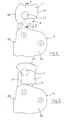
- the safety device 4 consists of a box 5 that is integral with the holster 1 and from the upper part of which there extends an arm 6 carrying a push-button 7.
- the arm 6 is integral with the strap 2 and can perform an angular displacement with respect to the box 5, in particular, can be turned through about 90°, dragging the strap 2 with as it moves.
- the arm 6 In conditions of normal use, i.e., when the weapon is at rest in the holster 1, the arm 6 cannot be rotated, because it is blocked with respect to the box, as will be explained further on, and the push-button 7 has to be depressed before it can be released and rotated.
- the box 5 is made up of two shells 5a and 5b that are paired and attached to each other by means of screws or in some other appropriate way.
- the arm 6 is provided with a slotted hole 6a that engages with a pin 8 projecting from the shell 5b of the box 5, while the bottom end 9 of the arm 6 is in contact with an elastic element 22 that keeps a tooth 10 of the arm 6 engaged within a corresponding seating 11 formed on a rigid plate 26 arranged within the shell 5b (see Figure 7).
- the arm 6 passes out of the box 5 by means of a throat 12 (which can be seen in Figure 8) that permits it to be angularly displaced.
- the shells 5a and 5b are provided with an arcuate groove in which the tooth 10 can slide.
- the push-button 7 is rotatably connected to the top end of the arm 6 by means of a pin 13 and can also perform an elastically opposed axial movement along said pin, as will be described further on.
- the top end of the arm 6 is provided with a head 14 and two symmetrical shoulders 15.
- a first seating 16 with an edge 16a that exactly reproduces the profile of the head 14 and the shoulders 15, so that the push-button 7 cannot rotate around the axis of the pin 13 when the head 14 is engaged in the seating 16.
- push-button 7 is integral to arm 6.
- a second seating 17 that is not as deep as the seating 16 and has an edge 17a that again reproduces the profile of the head 14 and of one shoulder 15 of the arm 6.
- the seatings 16 and 17 are arranged at substantially 90° with respect to each other, so that when the push-button 7 is displaced by means of rotation, it can be brought into two different positions with respect to the arm 6 that are substantially rotated through 90° with respect to each other and are shown in Figures 4 and 5.
- the rotatable and elastically sliding connection between the push-button 7 and the head 14 of the arm 6 is obtained by means of the pin 13, which is hollow, threaded on the inside and engaged in a seating 28 of the push-button 7.
- the bottom of the seating 28 is provided with an opening 28a in which the end of the pin 13 is engaged in order to come into contact with the arm 6, while around the pin 13 there is arranged a helical spring 29 that bears against the head of the pin and the bottom of the seating 28.
- a screw 30 that is screwed into the pin 13 and passes through the arm 6 locks the pin 13 with respect to the arm 6.
- the geometric conformation of the push-button 7 is such that, when the end of the arm 6 is engaged in the seating 17 of the push-button, any possible sliding of the arm 6 with respect to the box 5 is prevented, because the side 7a of the push-button 7 bears against the edge of the box 5 from which the arm 6 projects. This is due to the fact that the distance of the side 7a from the axis of the pin 13 is equal to or slightly smaller than the distance between the axis and the edge of the box 5 from which the arm 6 projects.
- the distance of the axis of the pin 13 from the side of the push-button 7 adjacent to the side 7a is significantly smaller than the distance from the same edge of the box 5, which makes it possible for the arm 6 to slide inside the box 5 after pressure has been exerted on the push-button 7.
- At least the side opposite the side 7a of the push-button 7 has a rifled surface 20 in order to create the greatest possible friction at the moment in which the arm 6 has to be released and allowed to move by rotating the push-button 7 from the position of Figure 5 to the position of Figure 4.
- the arm 6 will have a symmetrical form to permit its being used both with holsters worn on the right and holsters worn on the left.
- a tooth 21 that performs the same function, but faces in the opposite direction with respect to the plane that contains the arm 6, said tooth 21 being likewise capable of becoming engaged in the seating 11 ( Figure 7) provided in the shell 5b after the rotation has been completed.
- the broken line in Figure 8 indicates the position attained by the push-button 7 at the end of its rotation around the pin 8 and after it has been made to move inside the box 5 so as to disengage the tooth 10 (or 21) from the seating 11.
- a side stop 25 with which the push-button 7 comes into contact at the end of its rotation.
- a groove similar to the groove 27 is provided on the shell 5a in order to permit the simultaneous movement of the tooth 21 within the box 5.
- the means for locking the push-button 7 in either angularly spaced positions comprise a pair of angularly spaced seats 30 (only one shown in Figure 9, the other one being spaced about 90° apart) formed on the face of the end of arm 6 to which the push-button 7 is attached and ball 31 protruding from a respective seat 32 formed in the push-button 7 and elastically urged against said face of the arm 6 by a spring 33 housed in the seat 32.
- the safety device in accordance with the invention therefore makes it possible to lock the action of the push-button 7 on which one has to act in order to permit the rotation of the arm 6 and therefore of the strap 2.
- the operations of releasing the action of the push-button 7, releasing the rotation of the arm 6 and actually rotating the arm 6 can be carried out by means of a single and continuous action performed on the push-button 7, thus simplifying in a significant manner the pulling out of the weapon from the holster, though without compromising the safety of the device that retains the weapon in the holster.
Landscapes
- Engineering & Computer Science (AREA)
- General Engineering & Computer Science (AREA)
- Lock And Its Accessories (AREA)
- Burglar Alarm Systems (AREA)
- Catching Or Destruction (AREA)
- Emergency Lowering Means (AREA)
- Helmets And Other Head Coverings (AREA)
- Casings For Electric Apparatus (AREA)
Applications Claiming Priority (2)
| Application Number | Priority Date | Filing Date | Title |
|---|---|---|---|
| IT2002FI000134A ITFI20020134A1 (it) | 2002-07-19 | 2002-07-19 | Blocco di sicurezza per fondina |
| ITFI20020134 | 2002-07-19 |
Publications (2)
| Publication Number | Publication Date |
|---|---|
| EP1382931A1 true EP1382931A1 (de) | 2004-01-21 |
| EP1382931B1 EP1382931B1 (de) | 2008-09-17 |
Family
ID=29765279
Family Applications (1)
| Application Number | Title | Priority Date | Filing Date |
|---|---|---|---|
| EP03425477A Expired - Lifetime EP1382931B1 (de) | 2002-07-19 | 2003-07-16 | Sicherheitsschloss für Pistolenholster |
Country Status (4)
| Country | Link |
|---|---|
| EP (1) | EP1382931B1 (de) |
| AT (1) | ATE408799T1 (de) |
| DE (1) | DE60323570D1 (de) |
| IT (1) | ITFI20020134A1 (de) |
Cited By (4)
| Publication number | Priority date | Publication date | Assignee | Title |
|---|---|---|---|---|
| WO2010064268A1 (en) | 2008-12-05 | 2010-06-10 | Radar Leather Division S.R.L. | Holster with quick unlocking of weapon extraction |
| US20110174849A1 (en) * | 2010-01-18 | 2011-07-21 | Safariland, Llc | Locking device safety mechanism and related holster assembly |
| WO2011150468A3 (en) * | 2010-06-04 | 2012-03-22 | Thf Innovation Pty Ltd | Retaining mechanism for a handgun holster |
| US11098979B2 (en) | 2016-12-06 | 2021-08-24 | Thf Innovation Pty Ltd | Retaining mechanism for a holster |
Citations (3)
| Publication number | Priority date | Publication date | Assignee | Title |
|---|---|---|---|---|
| US5199620A (en) * | 1989-10-11 | 1993-04-06 | Strong Holster Company | Security holster thumb-break |
| US5441187A (en) * | 1994-02-15 | 1995-08-15 | Mixson Leathercraft | Holster safety snap assembly |
| EP0971196A2 (de) * | 1998-07-08 | 2000-01-12 | Bianchi International | Sekundäres Verriegelungselement für einen Holster |
-
2002
- 2002-07-19 IT IT2002FI000134A patent/ITFI20020134A1/it unknown
-
2003
- 2003-07-16 DE DE60323570T patent/DE60323570D1/de not_active Expired - Fee Related
- 2003-07-16 EP EP03425477A patent/EP1382931B1/de not_active Expired - Lifetime
- 2003-07-16 AT AT03425477T patent/ATE408799T1/de not_active IP Right Cessation
Patent Citations (3)
| Publication number | Priority date | Publication date | Assignee | Title |
|---|---|---|---|---|
| US5199620A (en) * | 1989-10-11 | 1993-04-06 | Strong Holster Company | Security holster thumb-break |
| US5441187A (en) * | 1994-02-15 | 1995-08-15 | Mixson Leathercraft | Holster safety snap assembly |
| EP0971196A2 (de) * | 1998-07-08 | 2000-01-12 | Bianchi International | Sekundäres Verriegelungselement für einen Holster |
Cited By (5)
| Publication number | Priority date | Publication date | Assignee | Title |
|---|---|---|---|---|
| WO2010064268A1 (en) | 2008-12-05 | 2010-06-10 | Radar Leather Division S.R.L. | Holster with quick unlocking of weapon extraction |
| US20110174849A1 (en) * | 2010-01-18 | 2011-07-21 | Safariland, Llc | Locking device safety mechanism and related holster assembly |
| US8910839B2 (en) * | 2010-01-18 | 2014-12-16 | Safariland, Llc | Locking device safety mechanism and related holster assembly |
| WO2011150468A3 (en) * | 2010-06-04 | 2012-03-22 | Thf Innovation Pty Ltd | Retaining mechanism for a handgun holster |
| US11098979B2 (en) | 2016-12-06 | 2021-08-24 | Thf Innovation Pty Ltd | Retaining mechanism for a holster |
Also Published As
| Publication number | Publication date |
|---|---|
| DE60323570D1 (de) | 2008-10-30 |
| ITFI20020134A1 (it) | 2004-01-19 |
| ATE408799T1 (de) | 2008-10-15 |
| EP1382931B1 (de) | 2008-09-17 |
Similar Documents
| Publication | Publication Date | Title |
|---|---|---|
| US5832573A (en) | Quick release buckle assembly | |
| US6948644B1 (en) | Movable welt holster | |
| US5144725A (en) | Side-release buckle with accidental release guard | |
| US8807404B1 (en) | Holster retention device | |
| US20060226185A1 (en) | Holster for a handgun | |
| US20010032406A1 (en) | Holster security device | |
| US8365558B2 (en) | Safety handcuffs designed to facilitate the handcuffing of an individual | |
| US10634452B1 (en) | Auto retention holster | |
| WO2014204004A1 (ja) | 水中マスク | |
| US9889036B2 (en) | Joint orthosis | |
| US11905148B2 (en) | Snatch block with slide-open spring-biased cheek, dual-plunger lock release, and integral swivel stud | |
| EP1382931B1 (de) | Sicherheitsschloss für Pistolenholster | |
| EP2977710B1 (de) | Drehbarer holster | |
| CN114556042B (zh) | 手枪枪套 | |
| US4461110A (en) | Safety latch arrangement for use in a firearm | |
| US11209241B2 (en) | Handgun holster having a thumb-operated safety lock on the spent casing ejection port of the handgun | |
| US6948586B1 (en) | Quick release rappel device | |
| EP0376860A1 (de) | Sicherheitskarabinerhaken mit einem Stellungsanzeiger für den Verriegelungsring | |
| US10502523B1 (en) | Holster with locking hood | |
| WO2023168015A3 (en) | Rotating lock lever | |
| GB2077838A (en) | Safety clips for harnesses | |
| US10065057B1 (en) | Safety catch connector | |
| US3422559A (en) | Handgrip operated safety mechanism for handguns | |
| CN109091774B (zh) | 安全带扣环连接装置 | |
| US20260049790A1 (en) | Holster with protective feature |
Legal Events
| Date | Code | Title | Description |
|---|---|---|---|
| PUAI | Public reference made under article 153(3) epc to a published international application that has entered the european phase |
Free format text: ORIGINAL CODE: 0009012 |
|
| AK | Designated contracting states |
Kind code of ref document: A1 Designated state(s): AT BE BG CH CY CZ DE DK EE ES FI FR GB GR HU IE IT LI LU MC NL PT RO SE SI SK TR |
|
| AX | Request for extension of the european patent |
Extension state: AL LT LV MK |
|
| 17P | Request for examination filed |
Effective date: 20040707 |
|
| AKX | Designation fees paid |
Designated state(s): AT BE BG CH CY CZ DE DK EE ES FI FR GB GR HU IE IT LI LU MC NL PT RO SE SI SK TR |
|
| 17Q | First examination report despatched |
Effective date: 20070126 |
|
| GRAP | Despatch of communication of intention to grant a patent |
Free format text: ORIGINAL CODE: EPIDOSNIGR1 |
|
| GRAS | Grant fee paid |
Free format text: ORIGINAL CODE: EPIDOSNIGR3 |
|
| GRAA | (expected) grant |
Free format text: ORIGINAL CODE: 0009210 |
|
| AK | Designated contracting states |
Kind code of ref document: B1 Designated state(s): AT BE BG CH CY CZ DE DK EE ES FI FR GB GR HU IE IT LI LU MC NL PT RO SE SI SK TR |
|
| REG | Reference to a national code |
Ref country code: GB Ref legal event code: FG4D |
|
| REG | Reference to a national code |
Ref country code: CH Ref legal event code: EP |
|
| REG | Reference to a national code |
Ref country code: IE Ref legal event code: FG4D |
|
| REF | Corresponds to: |
Ref document number: 60323570 Country of ref document: DE Date of ref document: 20081030 Kind code of ref document: P |
|
| PG25 | Lapsed in a contracting state [announced via postgrant information from national office to epo] |
Ref country code: FI Free format text: LAPSE BECAUSE OF FAILURE TO SUBMIT A TRANSLATION OF THE DESCRIPTION OR TO PAY THE FEE WITHIN THE PRESCRIBED TIME-LIMIT Effective date: 20080917 Ref country code: SI Free format text: LAPSE BECAUSE OF FAILURE TO SUBMIT A TRANSLATION OF THE DESCRIPTION OR TO PAY THE FEE WITHIN THE PRESCRIBED TIME-LIMIT Effective date: 20080917 Ref country code: AT Free format text: LAPSE BECAUSE OF FAILURE TO SUBMIT A TRANSLATION OF THE DESCRIPTION OR TO PAY THE FEE WITHIN THE PRESCRIBED TIME-LIMIT Effective date: 20080917 |
|
| NLV1 | Nl: lapsed or annulled due to failure to fulfill the requirements of art. 29p and 29m of the patents act | ||
| PG25 | Lapsed in a contracting state [announced via postgrant information from national office to epo] |
Ref country code: BE Free format text: LAPSE BECAUSE OF FAILURE TO SUBMIT A TRANSLATION OF THE DESCRIPTION OR TO PAY THE FEE WITHIN THE PRESCRIBED TIME-LIMIT Effective date: 20080917 |
|
| PG25 | Lapsed in a contracting state [announced via postgrant information from national office to epo] |
Ref country code: BG Free format text: LAPSE BECAUSE OF FAILURE TO SUBMIT A TRANSLATION OF THE DESCRIPTION OR TO PAY THE FEE WITHIN THE PRESCRIBED TIME-LIMIT Effective date: 20081217 Ref country code: ES Free format text: LAPSE BECAUSE OF FAILURE TO SUBMIT A TRANSLATION OF THE DESCRIPTION OR TO PAY THE FEE WITHIN THE PRESCRIBED TIME-LIMIT Effective date: 20081228 |
|
| PG25 | Lapsed in a contracting state [announced via postgrant information from national office to epo] |
Ref country code: PT Free format text: LAPSE BECAUSE OF FAILURE TO SUBMIT A TRANSLATION OF THE DESCRIPTION OR TO PAY THE FEE WITHIN THE PRESCRIBED TIME-LIMIT Effective date: 20090217 Ref country code: RO Free format text: LAPSE BECAUSE OF FAILURE TO SUBMIT A TRANSLATION OF THE DESCRIPTION OR TO PAY THE FEE WITHIN THE PRESCRIBED TIME-LIMIT Effective date: 20080917 Ref country code: CZ Free format text: LAPSE BECAUSE OF FAILURE TO SUBMIT A TRANSLATION OF THE DESCRIPTION OR TO PAY THE FEE WITHIN THE PRESCRIBED TIME-LIMIT Effective date: 20080917 Ref country code: NL Free format text: LAPSE BECAUSE OF FAILURE TO SUBMIT A TRANSLATION OF THE DESCRIPTION OR TO PAY THE FEE WITHIN THE PRESCRIBED TIME-LIMIT Effective date: 20080917 Ref country code: SK Free format text: LAPSE BECAUSE OF FAILURE TO SUBMIT A TRANSLATION OF THE DESCRIPTION OR TO PAY THE FEE WITHIN THE PRESCRIBED TIME-LIMIT Effective date: 20080917 |
|
| PLBE | No opposition filed within time limit |
Free format text: ORIGINAL CODE: 0009261 |
|
| STAA | Information on the status of an ep patent application or granted ep patent |
Free format text: STATUS: NO OPPOSITION FILED WITHIN TIME LIMIT |
|
| PG25 | Lapsed in a contracting state [announced via postgrant information from national office to epo] |
Ref country code: DK Free format text: LAPSE BECAUSE OF FAILURE TO SUBMIT A TRANSLATION OF THE DESCRIPTION OR TO PAY THE FEE WITHIN THE PRESCRIBED TIME-LIMIT Effective date: 20080917 Ref country code: EE Free format text: LAPSE BECAUSE OF FAILURE TO SUBMIT A TRANSLATION OF THE DESCRIPTION OR TO PAY THE FEE WITHIN THE PRESCRIBED TIME-LIMIT Effective date: 20080917 |
|
| 26N | No opposition filed |
Effective date: 20090618 |
|
| PG25 | Lapsed in a contracting state [announced via postgrant information from national office to epo] |
Ref country code: IT Free format text: LAPSE BECAUSE OF FAILURE TO SUBMIT A TRANSLATION OF THE DESCRIPTION OR TO PAY THE FEE WITHIN THE PRESCRIBED TIME-LIMIT Effective date: 20080917 |
|
| PGFP | Annual fee paid to national office [announced via postgrant information from national office to epo] |
Ref country code: FR Payment date: 20090716 Year of fee payment: 7 |
|
| PGFP | Annual fee paid to national office [announced via postgrant information from national office to epo] |
Ref country code: DE Payment date: 20090722 Year of fee payment: 7 Ref country code: GB Payment date: 20090720 Year of fee payment: 7 |
|
| PG25 | Lapsed in a contracting state [announced via postgrant information from national office to epo] |
Ref country code: SE Free format text: LAPSE BECAUSE OF FAILURE TO SUBMIT A TRANSLATION OF THE DESCRIPTION OR TO PAY THE FEE WITHIN THE PRESCRIBED TIME-LIMIT Effective date: 20081217 |
|
| PG25 | Lapsed in a contracting state [announced via postgrant information from national office to epo] |
Ref country code: MC Free format text: LAPSE BECAUSE OF NON-PAYMENT OF DUE FEES Effective date: 20090731 |
|
| REG | Reference to a national code |
Ref country code: CH Ref legal event code: PL |
|
| REG | Reference to a national code |
Ref country code: IE Ref legal event code: MM4A |
|
| PG25 | Lapsed in a contracting state [announced via postgrant information from national office to epo] |
Ref country code: LI Free format text: LAPSE BECAUSE OF NON-PAYMENT OF DUE FEES Effective date: 20090731 Ref country code: CH Free format text: LAPSE BECAUSE OF NON-PAYMENT OF DUE FEES Effective date: 20090731 |
|
| PG25 | Lapsed in a contracting state [announced via postgrant information from national office to epo] |
Ref country code: IE Free format text: LAPSE BECAUSE OF NON-PAYMENT OF DUE FEES Effective date: 20090716 |
|
| PG25 | Lapsed in a contracting state [announced via postgrant information from national office to epo] |
Ref country code: GR Free format text: LAPSE BECAUSE OF FAILURE TO SUBMIT A TRANSLATION OF THE DESCRIPTION OR TO PAY THE FEE WITHIN THE PRESCRIBED TIME-LIMIT Effective date: 20081218 |
|
| GBPC | Gb: european patent ceased through non-payment of renewal fee |
Effective date: 20100716 |
|
| REG | Reference to a national code |
Ref country code: FR Ref legal event code: ST Effective date: 20110331 |
|
| PG25 | Lapsed in a contracting state [announced via postgrant information from national office to epo] |
Ref country code: DE Free format text: LAPSE BECAUSE OF NON-PAYMENT OF DUE FEES Effective date: 20110201 Ref country code: LU Free format text: LAPSE BECAUSE OF NON-PAYMENT OF DUE FEES Effective date: 20090716 |
|
| REG | Reference to a national code |
Ref country code: DE Ref legal event code: R119 Ref document number: 60323570 Country of ref document: DE Effective date: 20110201 |
|
| PG25 | Lapsed in a contracting state [announced via postgrant information from national office to epo] |
Ref country code: FR Free format text: LAPSE BECAUSE OF NON-PAYMENT OF DUE FEES Effective date: 20100802 |
|
| PG25 | Lapsed in a contracting state [announced via postgrant information from national office to epo] |
Ref country code: HU Free format text: LAPSE BECAUSE OF FAILURE TO SUBMIT A TRANSLATION OF THE DESCRIPTION OR TO PAY THE FEE WITHIN THE PRESCRIBED TIME-LIMIT Effective date: 20090318 |
|
| PG25 | Lapsed in a contracting state [announced via postgrant information from national office to epo] |
Ref country code: GB Free format text: LAPSE BECAUSE OF NON-PAYMENT OF DUE FEES Effective date: 20100716 |
|
| PG25 | Lapsed in a contracting state [announced via postgrant information from national office to epo] |
Ref country code: TR Free format text: LAPSE BECAUSE OF FAILURE TO SUBMIT A TRANSLATION OF THE DESCRIPTION OR TO PAY THE FEE WITHIN THE PRESCRIBED TIME-LIMIT Effective date: 20080917 |
|
| PG25 | Lapsed in a contracting state [announced via postgrant information from national office to epo] |
Ref country code: CY Free format text: LAPSE BECAUSE OF FAILURE TO SUBMIT A TRANSLATION OF THE DESCRIPTION OR TO PAY THE FEE WITHIN THE PRESCRIBED TIME-LIMIT Effective date: 20080917 |