EP1383108A1 - Avertisseur pour génération de son - Google Patents
Avertisseur pour génération de son Download PDFInfo
- Publication number
- EP1383108A1 EP1383108A1 EP02255066A EP02255066A EP1383108A1 EP 1383108 A1 EP1383108 A1 EP 1383108A1 EP 02255066 A EP02255066 A EP 02255066A EP 02255066 A EP02255066 A EP 02255066A EP 1383108 A1 EP1383108 A1 EP 1383108A1
- Authority
- EP
- European Patent Office
- Prior art keywords
- diaphragm
- horn
- switching
- circuitry
- position sensor
- Prior art date
- Legal status (The legal status is an assumption and is not a legal conclusion. Google has not performed a legal analysis and makes no representation as to the accuracy of the status listed.)
- Withdrawn
Links
- 230000003534 oscillatory effect Effects 0.000 claims abstract description 5
- 230000001360 synchronised effect Effects 0.000 claims abstract description 5
- 230000000694 effects Effects 0.000 claims abstract description 3
- 230000005669 field effect Effects 0.000 claims description 15
- 230000005355 Hall effect Effects 0.000 claims description 3
- 239000007787 solid Substances 0.000 claims description 2
- 238000010276 construction Methods 0.000 description 4
- 238000010586 diagram Methods 0.000 description 3
- 239000003990 capacitor Substances 0.000 description 1
- 230000007797 corrosion Effects 0.000 description 1
- 238000005260 corrosion Methods 0.000 description 1
- 239000013078 crystal Substances 0.000 description 1
- 230000001419 dependent effect Effects 0.000 description 1
- 230000000994 depressogenic effect Effects 0.000 description 1
- 230000009977 dual effect Effects 0.000 description 1
- 230000008030 elimination Effects 0.000 description 1
- 238000003379 elimination reaction Methods 0.000 description 1
- 230000007613 environmental effect Effects 0.000 description 1
- 230000004048 modification Effects 0.000 description 1
- 238000012986 modification Methods 0.000 description 1
- 230000001105 regulatory effect Effects 0.000 description 1
Images

Classifications
-
- G—PHYSICS
- G10—MUSICAL INSTRUMENTS; ACOUSTICS
- G10K—SOUND-PRODUCING DEVICES; METHODS OR DEVICES FOR PROTECTING AGAINST, OR FOR DAMPING, NOISE OR OTHER ACOUSTIC WAVES IN GENERAL; ACOUSTICS NOT OTHERWISE PROVIDED FOR
- G10K9/00—Devices in which sound is produced by vibrating a diaphragm or analogous element, e.g. fog horns, vehicle hooters or buzzers
- G10K9/12—Devices in which sound is produced by vibrating a diaphragm or analogous element, e.g. fog horns, vehicle hooters or buzzers electrically operated
- G10K9/13—Devices in which sound is produced by vibrating a diaphragm or analogous element, e.g. fog horns, vehicle hooters or buzzers electrically operated using electromagnetic driving means
- G10K9/15—Self-interrupting arrangements
Definitions
- the present invention relates to a horn for generating a sound comprising a diaphragm, vibration of which causes a sound to be generated, and switching circuitry connected to vibrate the diaphragm in such a fashion that switching of the circuitry is synchronized with the oscillatory movement of the diaphragm, in which the switching circuitry comprises a main switching device through which a power electrical current passes at a power voltage to effect vibration of the diaphragm.
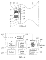
- Figure 1 shows an axial sectional view of such a horn.
- the horn shown in Figure 1 comprises a diaphragm 10 held around its periphery by the lip 12 of a housing 14 so that central regions of the diaphragm are able to vibrate to and fro in an axial direction of the horn.
- a pole piece 16 is secured to a rear side of the centre of the diaphragm 10. It is formed with a switch protuberance 18 which projects in a radial direction from one side of the pole piece.
- a coil core 20 is secured to the housing 14 on the interior thereof rearwardly and in registration with the pole piece 16. The coil core is surrounded by a coil 22 which is seated within a cylindrical portion 24 of the housing 14.
- Two metallic power terminals 26 project rearwardly from the housing 14 on opposite sides of the cylindrical portion 24 thereof.
- a wire 28 extends from one of the power terminals to the coil, the other end of which is connected via a further wire 30 to one side of a make-and-break contact switch 32.
- the other side of this make-and-break contact switch 32 is connected to the other power terminal 26 via a further wire 34.
- a nozzle-shaped horn tube 36 extends axially forwardly from the diaphragm 10.
- the magnetic field created by the coil 24 magnetizes the coil core 20 which as a result attracts the pole piece 16 towards it.
- the switching protuberance 18 thereby comes into contact with one side of the make-and-break contact switch 32 so that the contact parts thereof are physically separated. This breaks the circuitry between the power terminals 26.
- the coil as a result no longer has an electrical current passing through it, a magnetic field is no longer generating along its axis, and the coil core 20 is no longer magnetized, so that the pole piece 16 is no longer drawn towards it and the natural resilience of the diaphragm 10 causes it to be restored towards its rest position and beyond.
- any switch which is provided to turn the horn on has the full power current passing through it, or else it needs a relay to operate the horn indirectly.
- the make and break contacts tend to wear through arcing.
- the present invention seeks to obviate one or both of these disadvantages.
- the present invention is directed to a horn for generating sound having the construction set out in the opening paragraph of the present specification, in which the switching circuitry further comprises a position sensor arranged to cause a switching signal to be delivered to the main switching device at a switching electrical voltage, in dependence upon the position of the diaphragm.
- Such a horn may have a greatly extended working life relative to a conventional horn.
- the main switching device may comprise a field effect transistor.
- the position sensor may comprise a make and break contact switch. This has the advantage that more of the parts which are already in use in a conventional horn can be used to create a horn in accordance with the present invention. As a result, switching circuitry can be retrofitted into an existing horn to create such an embodiment of the present invention, to convert the horn to a long-life electronic horn.
- the position sensor may comprise an optocoupler, a Hall effect switch, or a piezo electric device.
- the switch circuitry may include a pulse width modulator to vary the proportion of time within a given interval for which an electrical voltage is applied across the horn, in dependence upon the level of the voltage applied across the horn.
- the circuitry shown in Figures 2 and 3 comprises a voltage source 210 connected to a voltage regulator 220.
- the latter provides a regulated operating voltage of +5 volts DC to a pulse width modulator 230 and also to an oscillator 240.
- the pulse width modulator 230 is provided with an input connected to receive an output from the oscillator 240, and with a further input to have applied to it a voltage which is dependent upon the voltage level of the voltage source 210.
- An output from the pulse width modulator 230 is connected (indirectly) to an input of a power switch 250.
- the latter is gated by gating switch 260, effectiveness of which is in turn controlled by a diaphragm position sensor 270 arranged in relation to a diaphragm 280 of the horn so that triggering signals issued from the diaphragm position sensor 270 are issued in dependence upon the position of the diaphragm 280.
- An actuating coil 290 is arranged to intermittently attract a pole piece 300 of the diaphragm 280, the diaphragm 280, the actuating coil 290 and the pole piece 300 being arranged in similar fashion to the diaphragm 10, the actuating coil 24 and the pole piece 16 of the horn shown in Figure 1.
- the actuating coil 290 is connected to be operated by the voltage source 210 in dependence upon the condition of the output power switch 250.
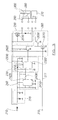
- the oscillator 240 comprises one half of a 556 timer 2410 constituting one half of a dual timer chip for the generation of a fixed frequency-square wave signal.
- the output 2420 of the 556 timer half 2410 is coupled via a capacitor 2430 to a triggering input 2310 of a second half of the 556 timer 2320.
- the 556 timer half 2320 is connected as a triggerable monostable. It has a control pin 2330 connected indirectly to the voltage source 210.
- a horn on/off switch 310 is connected indirectly to the switching input of a field effect transistor 2610 of the gating switch 260 via a small gauge, low current signal wire 311.
- the latter is also provided with a switching transistor 2620 having its switching input connected to the output of the pulse switch modulator 230, and its collector side connected to the source connection of the field effect transistor 2610 (the drain of which is earthed) and also to the switching input of a further switching transistor 2630.
- the collector of the switching transistor 2620 is also connected via a resistor to the voltage source 210.
- the collector of the switching transistor 2630 constitutes the output from the gating switch 260.
- the latter is connected to the switching input of a low internal resistance field effect transistor 2510 of the output power switch 250 via the diaphragm position sensor 270.
- the diaphragm position sensor 270 causes the circuit through the switching transistor 2630 to be broken. This inhibits the field effect transistor 2510 so that the current through the coil 290 ceases and the pole piece 300 is enabled to return to its rest position by virtue of the resilience of the diaphragm 280 so that the position sensor 270 now causes the circuit through the switching transistor 2630 to be closed, the field effect transistor 2510 to be enabled, a current to be passed through the actuating coil 290, once again causing the pole piece 300 to be attracted towards the coil 290. This therefore causes vibration of the diaphragm 280 in a manner similar to that described with reference to the horn shown in Figure 1, such that the switching of the current through the coil 290 is synchronized with the oscillatory motion of the diaphragm 280.
- a square wave signal is generated by the oscillator 240 to produce an output from the pulse width modulator 230 for a repeated predetermined period of time at the same frequency as the square wave signal it receives from the oscillator 240.
- the duration of the predetermined period is set by the voltage applied to the control pin 2330 of the 556 timer half 2320.
- the variation of the set predetermined period as a function of the voltage source 210 is shown in Figure 4.
- the predetermined period is the full duration of one cycle of the signal from the oscillator 240.
- the predetermined period is one half of one cycle of the signal from the oscillator 240. If the voltage is 36 volts, the predetermined period is one-third of the full cycle period.
- the operating frequency of the oscillator 240 is selected to be as low as possible, so as to minimize radio frequency interference emissions, whilst at the same time being high enough so as not to interfere with the resonance of the diaphragm 280 nor to be audible as an overtone of the horn sound.
- the pulse width modulator 230 thereby enables the horn to be operated substantially independently of the voltage level of the voltage source 210.
- the coil will not overheat even with a high voltage source, because the modulated current through the coil has an average value which is the same as what it would be were the coil's nominal rated voltage applied across it.
- the position sensor 270 may comprise a make-and-break contact, such as that described with reference to Figure 1, although it more preferably comprises a Hall effect switch, an opto-coupler or a piezo electric crystal.
- circuitry of Figures 2 and 3 may be enclosed in the housing or casing of the horn, such as the housing 14 in Figure 1. Indeed, apart from the interposition of the circuitry shown in Figures 2 and 3 between the contact switch 32 and the coil 22 of the horn shown in Figure 1, the horn of Figures 2 and 3 may be otherwise the same.
- the circuitry shown in Figures 2 and 3 enables the on/off switch 310 to be operated at low power, such as the power of digital TTL signals or CMOS signal level from, for example, a microcontroller or a control node of a multiplexed electrical system.
- the voltage source 210 may comprise batteries of a discrete voltage from 6 to 80 volts, inclusive.
Landscapes
- Physics & Mathematics (AREA)
- Electromagnetism (AREA)
- Engineering & Computer Science (AREA)
- Acoustics & Sound (AREA)
- Multimedia (AREA)
- Apparatuses For Generation Of Mechanical Vibrations (AREA)
Priority Applications (1)
| Application Number | Priority Date | Filing Date | Title |
|---|---|---|---|
| EP02255066A EP1383108A1 (fr) | 2002-07-19 | 2002-07-19 | Avertisseur pour génération de son |
Applications Claiming Priority (1)
| Application Number | Priority Date | Filing Date | Title |
|---|---|---|---|
| EP02255066A EP1383108A1 (fr) | 2002-07-19 | 2002-07-19 | Avertisseur pour génération de son |
Publications (1)
| Publication Number | Publication Date |
|---|---|
| EP1383108A1 true EP1383108A1 (fr) | 2004-01-21 |
Family
ID=29762712
Family Applications (1)
| Application Number | Title | Priority Date | Filing Date |
|---|---|---|---|
| EP02255066A Withdrawn EP1383108A1 (fr) | 2002-07-19 | 2002-07-19 | Avertisseur pour génération de son |
Country Status (1)
| Country | Link |
|---|---|
| EP (1) | EP1383108A1 (fr) |
Cited By (3)
| Publication number | Priority date | Publication date | Assignee | Title |
|---|---|---|---|---|
| WO2010026074A3 (fr) * | 2008-08-25 | 2010-12-23 | Clarton Horn S.A. | Générateur acoustique |
| DE102013221182A1 (de) | 2013-10-18 | 2015-04-23 | Volkswagen Aktiengesellschaft | Akustisches Signalisierungssystem sowie Anordnung und Verfahren zum Betreiben eines akustischen Signalisierungssystems für ein Kraftfahrzeug |
| JP2020181115A (ja) * | 2019-04-25 | 2020-11-05 | 本田技研工業株式会社 | ホーン制御装置 |
Citations (6)
| Publication number | Priority date | Publication date | Assignee | Title |
|---|---|---|---|---|
| FR2573559A1 (fr) * | 1984-11-22 | 1986-05-23 | Bosch Gmbh Robert | Procede pour la commande sans contact de la frequence motrice de l'armature oscillante d'un klaxon electromagnetique |
| EP0266485A2 (fr) * | 1986-11-05 | 1988-05-11 | ELECTRONSYSTEM S.p.A. | Trompe électromagnétique avec excitation d'un diaphragme acoustique commandé électroniquement au moyen de capteurs mesurant sa fréquence de résonance |
| DE4409279A1 (de) * | 1994-03-18 | 1995-09-21 | Fer Fahrzeugelektrik Gmbh | Schaltungsanordnung für einen akustischen Signalgeber |
| US5457437A (en) * | 1991-06-08 | 1995-10-10 | Mando Machinery Corporation | Sparking free circuit of electric horn |
| DE19833927C1 (de) * | 1998-07-28 | 1999-10-28 | Harting Kgaa | Elektrisches Steckverbindungsteil zum Anschluß eines elektrischen Verbrauchers |
| FR2795853A1 (fr) * | 1999-06-30 | 2001-01-05 | Composants Electr Soc D | Systeme de rupteur magnetique pour avertisseur sonore |
-
2002
- 2002-07-19 EP EP02255066A patent/EP1383108A1/fr not_active Withdrawn
Patent Citations (6)
| Publication number | Priority date | Publication date | Assignee | Title |
|---|---|---|---|---|
| FR2573559A1 (fr) * | 1984-11-22 | 1986-05-23 | Bosch Gmbh Robert | Procede pour la commande sans contact de la frequence motrice de l'armature oscillante d'un klaxon electromagnetique |
| EP0266485A2 (fr) * | 1986-11-05 | 1988-05-11 | ELECTRONSYSTEM S.p.A. | Trompe électromagnétique avec excitation d'un diaphragme acoustique commandé électroniquement au moyen de capteurs mesurant sa fréquence de résonance |
| US5457437A (en) * | 1991-06-08 | 1995-10-10 | Mando Machinery Corporation | Sparking free circuit of electric horn |
| DE4409279A1 (de) * | 1994-03-18 | 1995-09-21 | Fer Fahrzeugelektrik Gmbh | Schaltungsanordnung für einen akustischen Signalgeber |
| DE19833927C1 (de) * | 1998-07-28 | 1999-10-28 | Harting Kgaa | Elektrisches Steckverbindungsteil zum Anschluß eines elektrischen Verbrauchers |
| FR2795853A1 (fr) * | 1999-06-30 | 2001-01-05 | Composants Electr Soc D | Systeme de rupteur magnetique pour avertisseur sonore |
Cited By (4)
| Publication number | Priority date | Publication date | Assignee | Title |
|---|---|---|---|---|
| WO2010026074A3 (fr) * | 2008-08-25 | 2010-12-23 | Clarton Horn S.A. | Générateur acoustique |
| DE102013221182A1 (de) | 2013-10-18 | 2015-04-23 | Volkswagen Aktiengesellschaft | Akustisches Signalisierungssystem sowie Anordnung und Verfahren zum Betreiben eines akustischen Signalisierungssystems für ein Kraftfahrzeug |
| DE102013221182B4 (de) * | 2013-10-18 | 2021-05-06 | Volkswagen Aktiengesellschaft | Akustisches Signalisierungssystem sowie Anordnung und Verfahren zum Betreiben eines akustischen Signalisierungssystems für ein Kraftfahrzeug |
| JP2020181115A (ja) * | 2019-04-25 | 2020-11-05 | 本田技研工業株式会社 | ホーン制御装置 |
Similar Documents
| Publication | Publication Date | Title |
|---|---|---|
| US20050035600A1 (en) | Inductive voltage generator | |
| US2635155A (en) | Synchronously-operated switch | |
| US2561355A (en) | Electric signal device | |
| JP2010152329A (ja) | 電子式平型警音器とフォトインタラプタを利用した警音器 | |
| EP0389860A2 (fr) | Klaxon contrôlé électroniquement pour véhicules à moteur | |
| EP1383108A1 (fr) | Avertisseur pour génération de son | |
| KR920701941A (ko) | 여진기를 갖는 전기호온 | |
| US4218626A (en) | Electromagnetic relay | |
| US2487052A (en) | Magnetic switch | |
| WO2010035123A2 (fr) | Klaxon électronique pour véhicule | |
| US5457437A (en) | Sparking free circuit of electric horn | |
| TW487605B (en) | Vibration-generating device and portable telephone comprising the same | |
| US3093743A (en) | Resonant reed frequency sensitive control apparatus | |
| EP0901719B1 (fr) | Dispositif a mouvement alternatif non lineaire | |
| EP0266485A2 (fr) | Trompe électromagnétique avec excitation d'un diaphragme acoustique commandé électroniquement au moyen de capteurs mesurant sa fréquence de résonance | |
| US3021520A (en) | Electric signaling device | |
| US3027554A (en) | Contactless direct current vibrating bell and motor mechanism | |
| US5907252A (en) | Driving circuit for electromagnetic relay | |
| US4736192A (en) | Excitation circuit for piezo-electric sound generators | |
| US2533695A (en) | Electromagnetic vibrator | |
| US3457522A (en) | Transistor oscillator with vibrating reed power supply | |
| GB2256963A (en) | Electric horn | |
| SU1412818A1 (ru) | Электромагнитный вибропривод | |
| KR20230089065A (ko) | 차량용 경음기 | |
| KR101080679B1 (ko) | 전자식 평형 경음기 |
Legal Events
| Date | Code | Title | Description |
|---|---|---|---|
| PUAI | Public reference made under article 153(3) epc to a published international application that has entered the european phase |
Free format text: ORIGINAL CODE: 0009012 |
|
| AK | Designated contracting states |
Kind code of ref document: A1 Designated state(s): AT BE BG CH CY CZ DE DK EE ES FI FR GB GR IE IT LI LU MC NL PT SE SK TR |
|
| AX | Request for extension of the european patent |
Extension state: AL LT LV MK RO SI |
|
| AKX | Designation fees paid | ||
| REG | Reference to a national code |
Ref country code: DE Ref legal event code: 8566 |
|
| STAA | Information on the status of an ep patent application or granted ep patent |
Free format text: STATUS: THE APPLICATION IS DEEMED TO BE WITHDRAWN |
|
| 18D | Application deemed to be withdrawn |
Effective date: 20040722 |