EP1383285B1 - System und Verfahren für Sitzungszulassungssteuerung - Google Patents
System und Verfahren für Sitzungszulassungssteuerung Download PDFInfo
- Publication number
- EP1383285B1 EP1383285B1 EP03016389A EP03016389A EP1383285B1 EP 1383285 B1 EP1383285 B1 EP 1383285B1 EP 03016389 A EP03016389 A EP 03016389A EP 03016389 A EP03016389 A EP 03016389A EP 1383285 B1 EP1383285 B1 EP 1383285B1
- Authority
- EP
- European Patent Office
- Prior art keywords
- bandwidth
- packets
- realm
- quality
- packet
- Prior art date
- Legal status (The legal status is an assumption and is not a legal conclusion. Google has not performed a legal analysis and makes no representation as to the accuracy of the status listed.)
- Expired - Lifetime
Links
- 238000000034 method Methods 0.000 title claims abstract description 21
- 238000004891 communication Methods 0.000 claims abstract description 75
- 230000005540 biological transmission Effects 0.000 claims abstract description 45
- 230000011664 signaling Effects 0.000 claims description 81
- 230000000977 initiatory effect Effects 0.000 claims description 3
- 230000002776 aggregation Effects 0.000 description 70
- 238000004220 aggregation Methods 0.000 description 70
- 238000005259 measurement Methods 0.000 description 13
- 238000012360 testing method Methods 0.000 description 10
- 230000006870 function Effects 0.000 description 9
- 238000012546 transfer Methods 0.000 description 9
- 238000013475 authorization Methods 0.000 description 8
- 238000010586 diagram Methods 0.000 description 8
- 230000004044 response Effects 0.000 description 6
- 230000004048 modification Effects 0.000 description 4
- 238000012986 modification Methods 0.000 description 4
- 230000003287 optical effect Effects 0.000 description 4
- 230000008569 process Effects 0.000 description 4
- 238000012545 processing Methods 0.000 description 4
- 238000004458 analytical method Methods 0.000 description 3
- 238000004422 calculation algorithm Methods 0.000 description 3
- RGNPBRKPHBKNKX-UHFFFAOYSA-N hexaflumuron Chemical compound C1=C(Cl)C(OC(F)(F)C(F)F)=C(Cl)C=C1NC(=O)NC(=O)C1=C(F)C=CC=C1F RGNPBRKPHBKNKX-UHFFFAOYSA-N 0.000 description 3
- 230000007246 mechanism Effects 0.000 description 3
- 230000006855 networking Effects 0.000 description 3
- 238000011144 upstream manufacturing Methods 0.000 description 3
- STMIIPIFODONDC-UHFFFAOYSA-N 2-(2,4-dichlorophenyl)-1-(1H-1,2,4-triazol-1-yl)hexan-2-ol Chemical compound C=1C=C(Cl)C=C(Cl)C=1C(O)(CCCC)CN1C=NC=N1 STMIIPIFODONDC-UHFFFAOYSA-N 0.000 description 2
- 101000741965 Homo sapiens Inactive tyrosine-protein kinase PRAG1 Proteins 0.000 description 2
- 102100038659 Inactive tyrosine-protein kinase PRAG1 Human genes 0.000 description 2
- 230000008859 change Effects 0.000 description 2
- 238000005516 engineering process Methods 0.000 description 2
- 239000000523 sample Substances 0.000 description 2
- 230000007727 signaling mechanism Effects 0.000 description 2
- 230000001360 synchronised effect Effects 0.000 description 2
- 230000008901 benefit Effects 0.000 description 1
- 239000000872 buffer Substances 0.000 description 1
- 238000004364 calculation method Methods 0.000 description 1
- 230000015556 catabolic process Effects 0.000 description 1
- 230000006835 compression Effects 0.000 description 1
- 238000007906 compression Methods 0.000 description 1
- 230000003247 decreasing effect Effects 0.000 description 1
- 230000007812 deficiency Effects 0.000 description 1
- 238000006731 degradation reaction Methods 0.000 description 1
- 230000001934 delay Effects 0.000 description 1
- 238000001514 detection method Methods 0.000 description 1
- 230000005012 migration Effects 0.000 description 1
- 238000013508 migration Methods 0.000 description 1
- 230000000737 periodic effect Effects 0.000 description 1
- 238000004886 process control Methods 0.000 description 1
- 230000002441 reversible effect Effects 0.000 description 1
- 238000000926 separation method Methods 0.000 description 1
- 238000004088 simulation Methods 0.000 description 1
- 230000003068 static effect Effects 0.000 description 1
Images




Classifications
-
- H—ELECTRICITY
- H04—ELECTRIC COMMUNICATION TECHNIQUE
- H04L—TRANSMISSION OF DIGITAL INFORMATION, e.g. TELEGRAPHIC COMMUNICATION
- H04L47/00—Traffic control in data switching networks
- H04L47/10—Flow control; Congestion control
- H04L47/15—Flow control; Congestion control in relation to multipoint traffic
-
- H—ELECTRICITY
- H04—ELECTRIC COMMUNICATION TECHNIQUE
- H04L—TRANSMISSION OF DIGITAL INFORMATION, e.g. TELEGRAPHIC COMMUNICATION
- H04L47/00—Traffic control in data switching networks
- H04L47/10—Flow control; Congestion control
- H04L47/24—Traffic characterised by specific attributes, e.g. priority or QoS
- H04L47/2441—Traffic characterised by specific attributes, e.g. priority or QoS relying on flow classification, e.g. using integrated services [IntServ]
-
- H—ELECTRICITY
- H04—ELECTRIC COMMUNICATION TECHNIQUE
- H04L—TRANSMISSION OF DIGITAL INFORMATION, e.g. TELEGRAPHIC COMMUNICATION
- H04L47/00—Traffic control in data switching networks
- H04L47/70—Admission control; Resource allocation
-
- H—ELECTRICITY
- H04—ELECTRIC COMMUNICATION TECHNIQUE
- H04L—TRANSMISSION OF DIGITAL INFORMATION, e.g. TELEGRAPHIC COMMUNICATION
- H04L47/00—Traffic control in data switching networks
- H04L47/70—Admission control; Resource allocation
- H04L47/80—Actions related to the user profile or the type of traffic
- H04L47/801—Real time traffic
-
- H—ELECTRICITY
- H04—ELECTRIC COMMUNICATION TECHNIQUE
- H04L—TRANSMISSION OF DIGITAL INFORMATION, e.g. TELEGRAPHIC COMMUNICATION
- H04L47/00—Traffic control in data switching networks
- H04L47/70—Admission control; Resource allocation
- H04L47/80—Actions related to the user profile or the type of traffic
- H04L47/805—QOS or priority aware
-
- H—ELECTRICITY
- H04—ELECTRIC COMMUNICATION TECHNIQUE
- H04L—TRANSMISSION OF DIGITAL INFORMATION, e.g. TELEGRAPHIC COMMUNICATION
- H04L47/00—Traffic control in data switching networks
- H04L47/70—Admission control; Resource allocation
- H04L47/82—Miscellaneous aspects
- H04L47/822—Collecting or measuring resource availability data
-
- H—ELECTRICITY
- H04—ELECTRIC COMMUNICATION TECHNIQUE
- H04L—TRANSMISSION OF DIGITAL INFORMATION, e.g. TELEGRAPHIC COMMUNICATION
- H04L65/00—Network arrangements, protocols or services for supporting real-time applications in data packet communication
- H04L65/1066—Session management
- H04L65/1101—Session protocols
- H04L65/1104—Session initiation protocol [SIP]
-
- H—ELECTRICITY
- H04—ELECTRIC COMMUNICATION TECHNIQUE
- H04L—TRANSMISSION OF DIGITAL INFORMATION, e.g. TELEGRAPHIC COMMUNICATION
- H04L65/00—Network arrangements, protocols or services for supporting real-time applications in data packet communication
- H04L65/60—Network streaming of media packets
- H04L65/61—Network streaming of media packets for supporting one-way streaming services, e.g. Internet radio
- H04L65/612—Network streaming of media packets for supporting one-way streaming services, e.g. Internet radio for unicast
-
- H—ELECTRICITY
- H04—ELECTRIC COMMUNICATION TECHNIQUE
- H04L—TRANSMISSION OF DIGITAL INFORMATION, e.g. TELEGRAPHIC COMMUNICATION
- H04L65/00—Network arrangements, protocols or services for supporting real-time applications in data packet communication
- H04L65/80—Responding to QoS
-
- H—ELECTRICITY
- H04—ELECTRIC COMMUNICATION TECHNIQUE
- H04L—TRANSMISSION OF DIGITAL INFORMATION, e.g. TELEGRAPHIC COMMUNICATION
- H04L67/00—Network arrangements or protocols for supporting network services or applications
- H04L67/14—Session management
-
- H—ELECTRICITY
- H04—ELECTRIC COMMUNICATION TECHNIQUE
- H04L—TRANSMISSION OF DIGITAL INFORMATION, e.g. TELEGRAPHIC COMMUNICATION
- H04L63/00—Network architectures or network communication protocols for network security
- H04L63/10—Network architectures or network communication protocols for network security for controlling access to devices or network resources
- H04L63/102—Entity profiles
-
- H—ELECTRICITY
- H04—ELECTRIC COMMUNICATION TECHNIQUE
- H04L—TRANSMISSION OF DIGITAL INFORMATION, e.g. TELEGRAPHIC COMMUNICATION
- H04L69/00—Network arrangements, protocols or services independent of the application payload and not provided for in the other groups of this subclass
- H04L69/30—Definitions, standards or architectural aspects of layered protocol stacks
- H04L69/32—Architecture of open systems interconnection [OSI] 7-layer type protocol stacks, e.g. the interfaces between the data link level and the physical level
- H04L69/322—Intralayer communication protocols among peer entities or protocol data unit [PDU] definitions
- H04L69/329—Intralayer communication protocols among peer entities or protocol data unit [PDU] definitions in the application layer [OSI layer 7]
Definitions
- Interfaces between different networks typically have constrained resources, which are further explained below.
- Examples of interfaces include, but are not limited to, T1/T3 connections, and digital subscriber line (DSL) or cable modem type connections.
- the capacity of the above-mentioned interfaces is significantly less than the capacity within networks.
- it is standard to use fast Ethernet within an enterprise network, wherein fast Ethernet supports data transfer rates of up to approximately one hundred Megabits per second (100Mbps).
- an interface between the enterprise network and a public data network may be a T1 connection, which supports data transfer rates of up to approximately 1.5Mbps.
- the maximum data transfer rate of the T1 connection is 1.5 percent of the maximum data transfer rate of the enterprise network. Therefore, packets that are to be transmitted from the enterprise network are queued and may ultimately be discarded after a timeout period as the packets wait to enter the constrained interface.
- QoS Quality of service
- Peering points between public data networks also have constrained interfaces that are typically a Gigabit Ethernet connection, an optical carrier three (OC3) connection or an OC12 connection. Fortunately, most network uses are tolerant of packet loss, and/or packet delays.
- OC3 optical carrier three
- VoIP Voice over Internet protocol
- PSTN public switched telephone network
- FIG. 1 is a block diagram of a prior art communication layout between a point-of-presence (POP) located within a public data network (PDN) aggregation point (referred to hereafter as PDN POP), a first aggregation realm 112 and a second aggregation realm 152.
- PDN POP public data network
- FIG. 1 is a block diagram of a prior art communication layout between a point-of-presence (POP) located within a public data network (PDN) aggregation point (referred to hereafter as PDN POP), a first aggregation realm 112 and a second aggregation realm 152.
- PDN POP public data network
- FIG. 1 is a block diagram of a prior art communication layout between a point-of-presence (POP) located within a public data network (PDN) aggregation point (referred to hereafter as PDN POP), a first aggregation realm 112 and a second aggregation realm 152.
- the PDN POP 102 contains an edge router 104 for routing data between the first aggregation realm 112 and the second aggregation realm 152 that are located downstream from the edge router 104 and separate from the PDN POP 102.
- edge routers include, but are not limited to, the Cisco 75xx, Cisco 10xxx and the Cisco 12xxx, manufactured by Cisco Systems, Inc. of San Jose, California, USA.
- the PDN POP 102 also contains a first aggregation device 148, which is preferably a layer-two aggregation device.
- An example of an aggregation device may be an aggregation switch, such as the Lucent CBX500, manufactured by Lucent Technologies of Murray Hill, New Jersey, USA.
- the first aggregation device 148 allows communication between a first enterprise 121, a second enterprise 131 and a third enterprise 141 located within the first aggregation realm 112.
- the first aggregation device 148 allows communication between the first aggregation realm 112 and the second aggregation realm 152.
- a second aggregation device 182 which is preferably a layer-two aggregation device, is also located within the PDN POP 102.
- the second aggregation device 182 allows communication between a first enterprise 161 and a second enterprise 171 located within the second aggregation realm 152.
- the second aggregation device 182 allows communication between the second aggregation device 152 and the first aggregation device 112.
- the first aggregation realm 112 contains the first enterprise 121, the second enterprise 131 and the third enterprise 141.
- the first enterprise 121 contains a first access router 122, a first private data network 124 and a first computer 126 for use by a user.
- the second enterprise 131 contains a second access router 132, a second private data network 134 and a second computer 136 for use by a user.
- the third enterprise 141 contains a third access router 142, a third private data network 144 and a third computer 146 for use by a user.
- Each access router 122, 132, 142 located within an enterprise 121, 131, 141 provides a connection from a computer 126, 136, 146 to the PDN POP 102.
- a fourth computer 172 is illustrated by FIG. 1, which provides a user with direct access to the PDN POP 102 from outside of the PDN POP 102.
- Each access router 122, 132, 142 provides a connection to one of the private data networks 124, 134, 144.
- the first access router 122 provides a connection to the first private data network 124.
- Each access router 122, 132, 142 also allows communication between a user, via a computer 126, 136, 146 and other portions of the first aggregation realm 112.
- the second aggregation realm 152 contains the first enterprise 161 and the second enterprise 171.
- the first enterprise 161 located within the second aggregation realm 152 contains a first modem 162 and a first computer 164, for use by a user.
- the second enterprise 171 located within the second aggregation realm 152 contains a second modem 172 and a second computer 174 for use by a user.
- the first modem 162 and the second modem 172 may be digital subscriber line (DSL) modems, or any other category of modem.
- DSL digital subscriber line
- Links connecting different portions of the PDN POP 102 may create constraints that force packets to be queued.
- the following provides an example of possible link properties within the PDN POP 102.
- Core network access links connecting the edge router 104 to devices within the PDN POP 102 may operate at OC48, which operates at approximately 2.5 Gigabits per second (Gps), or OC 192, which operates at approximately 10Gbps.
- the edge router 104 divides communication between the first aggregation device 148 located within the first aggregation realm 112 and the second aggregation device 182, located within the second aggregation realm 152. Lines of communication between the edge router 104 and the aggregation devices 148, 182 typically operate at packet over synchronous optical network seven (SONET 7) or SONET twenty (SONET 20).
- SONET 7 synchronous optical network seven
- SONET 20 SONET twenty
- the aggregation devices 148, 182 decrease data transmission speeds to lower speed connections including, for example, frame relay over T1 or T3, asynchronous transfer mode (ATM) over T3, point-to-point protocol (PPP) over a high speed serial interface (HSSI) and/or DSL.
- the access routers 122, 132, 142 and modems 162, 172 terminate links from the aggregation devices 148, 182 and convert bandwidth flows to 10/100 Ethernet. Therefore, the slowest links are between the aggregation devices 148, 182 and the access routers 122, 132, 142 or modems 162, 172.
- the edge router 104 is unaware of downstream bandwidth congestion. Edge routers may be programmed to build a queue for each logical end point in the POP PDN 102, thereby enabling a weighted fair distribution of packets based upon virtual downstream transmission capacity. Edge router weighted fair distribution queuing is not presently used to address bandwidth congestion for numerous reasons including, but not limited to, degradation in performance of the edge router and potentially complex provisioning mechanisms for which to plan.
- edge routers and access routers can sequence packets to prevent queuing or discarding of packets.
- techniques for identifying which packets are real-time packets require expensive packet classification microcircuits and configuration. Therefore, most existing edge routers and access routers would need to be updated or replaced.
- RSVP resource reservation setup protocol
- RSVP is a protocol that allows a software application to reserve resources from a source to a destination along a routed path comprising one or more packet routers. Thereafter, RSVP-enabled routers may schedule and prioritize packets to fulfill QoS requirements. RSVP associates bandwidth requests with destination IP addresses, many of which are reused by enterprise firewalls. Therefore, a real-time flow could be replaced by a standard flow, however bandwidth allocation for real-time flows would be valid until an RSVP time-out.
- RSVP packet classification
- SIP Session Initiation Protocol
- COPS is a protocol used to transmit from a policy decision point (PDP) to a policy enforcement point (PEP).
- PDP policy decision point
- PEP policy enforcement point
- the token does not include a measure of quality based on an originating realm that may be located downstream from an aggregation device located within a network.
- policy-based admissions are being performed based on resources provisioned in the edge router that may not reflect downstream limitations.
- the source sends a burst of packets to the destination test point, which then transits the burst of packets back to the source.
- the source of the probe can then estimate jitter, packet-loss, and latency from the burst.
- jitter is a measurement of the variation of the gap between packets on a flow.
- An alternative definition is that jitter is the variance in latency for a multimedia flow.
- the burst of packets is intended to resemble a packet flow requesting admission to the destination. Therefore, if the packet flow is, for example, a G.711 flow, the burst of packets reflects that the packet flow is a G.711 flow.
- admission of the packets to the destination may resume.
- One problem with this technique is that it requires a destination address for the packet flow to be known prior to transmission. Many signaling protocols are routable or travel through proxies and gateways. It is often the case that addresses are not known until there is a successful setup of the packet flow via signaling. Unfortunately, waiting until there is a successful setup of the packet flow may be too late to stop the packet flow from alerting or ringing the destination. Therefore, a signaling system would announce the arrival of a communication session, before a bandwidth path has been allocated.
- RSVP authorization element for session admission control. This element can be used to request bandwidth from an edge router that supports RSVP. Since edge routers are not currently capable of measuring quality on a flow-by-flow basis, there is no minimum required quality based admission control in the RSVP authorization element. Additionally, there is no support for downstream aggregation limitations that may be advisory. In addition, the RSVP authorization element is based on IP addresses.
- RSVP authorization element may not be capable of differentiating between a real-time transport protocol (RTP) flow and a file transfer protocol (FTP) flow arriving from the same network point. Therefore, a multimedia session may not be supported by RSVP authorization elements until the elements are protocol aware and session aware.
- RTP real-time transport protocol
- FTP file transfer protocol
- the protocol is a signaling mechanism to insert a manager between a LAN and an RSVP based layer 3 routing network.
- this Internet draft does not contain a mechanism for performing admission control based on actual observed quality or on nested layers of aggregation links.
- Sitara Networks of Waltham Massachusettes, USA builds products that perform deep packet analysis to assist in support of VoIP in enterprise networks, an example of which is QosArray TM.
- the QosArray product integrates high touch packet processing and classification with layer 2 quality schemes, such as 802.1p, and virtual LANs (VLANs), such as 802.1 q, to prioritize VoIP at access points to constrained links, such as wide area network (WAN) connections between networks.
- the Sitara products are not signaling aware and, therefore, cannot reject a communication attempt. This may result in a packet flow being rejected, however neither the source nor the destination of the packet flow will be aware of the flow rejection. Rejection of the packet flow without notice will most likely result in an unexpected outcome.
- the NetEnforcerTM does special processing on VoIP packets to perform per flow queuing.
- the NetEnforcerTM also splits packets (e.g., a packet with 20ms of speech is split into two packets, each with 10ms of speech) to guarantee that there will be less latency injected on slow speed transmissions within a WAN.
- the NetEnforcer works in a COPS or RSVP based router network to perform packet admission control.
- the NetEnforcerTM does not participate in signaling plans (i.e., SIP, media gateway control protocol (MGCP), H.323), does not measure packet quality in real-time and does not incorporate packet quality into an admission decision.
- United States (U.S.) patent number 6,404,864 (hereafter, the '864 patent), to Evslin et. al., discloses a network routing scheme to control the routing of telephone calls based on quality measurements. The quality measurements are collected at the end of each call, tabulated, and used to make subsequent routing decisions. Therefore, quality is not measured in real-time. Additionally, the '864 patent does not describe advisory bandwidth limits per realm, does not disclose the notion of downstream or upstream networks, and does not prevent telephone calls from being admitted to a network. Instead, the '864 patent describes the controlling of routing once a telephone call is admitted to the network.
- U.S. Patent Application Publication 2001/0043571 apparently discloses a system, method, and device for use in videoconferencing.
- the method typically includes installing a videoconferencing switch at an access point to an IP network and registering a plurality of subscribers for videoconferencing services. Each subscriber typically has a plurality of endpoints.
- the method further includes receiving subscriber-specific settings to be applied to multiple videoconferencing calls from the plurality of endpoints associated with each subscriber.
- the method further includes storing the subscriber-specific settings at a location accessible to the switch and configuring the switch to connect calls from the plurality of endpoints to each subscriber based on the corresponding subscriber-specific settings.
- the document also discloses a signaling proxy configured to determine bandwidth availability, to allocate bandwidth for transmission of multimedia packets, and to manage the allocated bandwidth and ensure that bandwidth quality and quantity is appropriate for transmission of multimedia packets.
- U.S. Patent Application Publication 2002/0016937 apparently utilizes a network processor as part of a test system for testing network environments and devices, and particularly VOIP networks and devices.
- the network processor is used as part of the test system and is precisely controlled by software to provide a variety of functions in order to test a network environment and devices.
- the test system incorporating the network processor may be programmed to process packets, create packets, receive packets and analyze packets.
- the test system thus provides simulation of network conditions using high bandwidth interfaces, a sniffmg functionality with packet to flow correlation on high bandwidth interfaces, the capture and/or creation of network profiles, and analysis of network packets.
- packet flow control and QoS packet flow admission control not only prior to entrance of packets to a network, such as the PDN POP 102 of FIG. 1, but also downstream from an edge router and as the packet flow leaves the network and is admitted to another network.
- the first claim of the present invention generally relates to a system for providing session admission control.
- the system utilizes a source of a communication request and a session director.
- the session director is used for allocating bandwidth to accommodate a bandwidth allocation request from the source, for ensuring that quantity of the allocated bandwidth is appropriate for transmission of multimedia packets from the source to the session director, and for ensuring that quality of service of the allocated bandwidth is appropriate to provide a flow of the multimedia packets via the allocated bandwidth.
- the present invention can also be viewed as providing a method of providing session admission control.
- the method can be broadly summarized by the following steps: allocating bandwidth to accommodate a bandwidth allocation request; ensuring that quantity of the allocated bandwidth is appropriate for transmission of multimedia packets; and ensuring that quality of service of the allocated bandwidth is appropriate to provide a flow of the multimedia packets via the allocated bandwidth.
- FIG. 2 is a block diagram illustrating a communication layout in accordance with a first exemplary embodiment of the invention. Specifically, FIG. 2 illustrates a communication layout between a PDN POP 202, a second session director 205 located at a network peering point connected to the PDN POP 202, a first aggregation realm 212 and a second aggregation realm 252.
- the session directors 203, 205 provide packet flow control and QoS packet flow admission control, not only prior to entrance of packets to the PDN POP 202, but also downstream from an edge router and as the packet flow leaves the PDN POP 202 network and is admitted to other networks 206.
- the session directors 203, 205 may be located within any category of network, instead of within the PDN POP 202 of FIG. 2. Examples of alternative network locations may include enterprise networks, constrained points within a core network such as access to a submarine transport link, etc.
- the session directors 203, 205 may be utilized anywhere that there may be a contention for access to a slower bandwidth transport link.
- the PDN POP 202 contains an edge router 204 for routing data between the first aggregation realm 212 and the second aggregation realm 252 that are located downstream from the edge router 204.
- the PDN POP 202 also contains a first aggregation device 248, which is preferably a layer-two aggregation device.
- the first aggregation device 248 enables communication between a first enterprise 221, a second enterprise 231 and a third enterprise 241 located within the first aggregation realm 212.
- the first aggregation device 248 enables communication between the first aggregation realm 212 and the second aggregation realm 252. Since those having ordinary skill in the art have knowledge of how aggregation devices enable communication, the present disclosure does not further describe how an aggregation device enables communication.
- a second aggregation device 282 which is preferably a layer-two aggregation device, is also located within the PDN POP 202.
- the second aggregation device 282 enables communication between a first enterprise 261 and a second enterprise 271 located within the second aggregation realm 252.
- the second aggregation device 282 enables communication between the second aggregation realm 252 and the first aggregation realm 212.
- the first aggregation realm 212 contains the first enterprise 221, the second enterprise 231 and the third enterprise 241.
- the first enterprise 221 contains a first access router 222, a first private data network 224 and a first computer 226 for use by a user.
- the second enterprise 231 contains a second access router 232, a second private data network 234 and a second computer 236 for use by a user.
- the third enterprise 241 contains a third access router 242, a third private data network 244 and a third computer 246 for use by a user. It should be noted that it is not necessary for the user to communicate via use of a computer. Instead, the user may communicate via use of any communication device, examples of which include, but are not limited to, VoIP telephones, such as the Pingtel VoIP telephone, IP telephones and VoIP gateways.
- Each access router 222, 232, 242 located within an enterprise 221, 231, 241 provides a connection from a computer 226, 236, 246 to the PDN POP 202.
- Users of network services made available by the PDN POP 202 may be connected to the PDN POP 202 from within the PDN POP 202, or from a location external to the PDN POP 202, such as the first computer 226, the second computer 236 and the third computer 246.
- a fourth computer 272 is illustrated by FIG. 2, which also provides a user with direct access to the PDN POP 202 from outside of the PDN POP 202.
- Each access router 222, 232, 242 provides a connection to one of the private data networks 224, 234, 244.
- the first access router 222 provides a connection to the first private data network 224.
- Each access router 222, 232, 242 also allows communication between a user, via a computer 226, 236, 246, and other portions of the first aggregation realm 212.
- the second aggregation realm 252 contains the first enterprise 261 and the second enterprise 271.
- the first enterprise 261 located within the second aggregation realm 252 contains a first modem 262 and a first computer 264, for use by a user.
- the second enterprise 271 located within the second aggregation realm 252 contains a second modem 272 and a second computer 274, for use by a user.
- the first modem 262 and the second modem 272 may be DSL modems, or any other category of modem.
- the first session director 203 is located at a service edge of the POP PDN 202, where the first session director 203 allocates and manages bandwidth for a source of a communication request located either internal or external to the PDN POP 202, and ensures that quality and quantity of the allocated bandwidth is appropriate for communication.
- the source of the communication request were either the first computer 226, the second computer 236 or the third computer 246 within the first aggregation realm 212
- bandwidth would be allocated and managed between the edge router 204 and either the first access router 222, the second access router 232, or the third access router 242, respectively.
- the source of the communication request were either the first computer 264 or the second computer 274 within the second aggregation realm 252, bandwidth would be allocated and managed between the edge router 204 and either the first modem 262 or the second modem 272, respectively.
- the second session director 205 is located at a network peering point that is connected to the PDN POP 202.
- the second session director 205 allocates and manages bandwidth for a source of a communication request located either internal or external to the PDN POP 202, ensures that quality and quantity of the allocated bandwidth is appropriate for communication.
- bandwidth would be allocated and managed between the edge router 204 and a device, such as, but not limited to, an access router or modem within the remote network. Functions performed by the first session director 203 and the second session director 205 are described in detail below.
- FIG. 3 is a block diagram that further illustrates the first session director 203 of FIG. 2.
- the second session director 205 (FIG. 2) contains the same components and performs the same functions as the first session director 203. Therefore, the following description of the first session director 203 is also applicable to the second session director 205 (FIG. 2).
- the arrangement of components within FIG. 3 is not intended to represent a sequential order to packet processing.
- the first session director 203 contains a first interface 302 and a second interface 304. It should be noted that there may be additional or fewer interfaces located within the first session director 203.
- the first interface 302 is used by the first session director 203 for receiving multimedia packets and signaling messages that establish a path of communication for the multimedia packets.
- the second interface 304 is used by the first session director 203 for transmitting multimedia packets and signaling messages.
- Each interface 302, 304 is assigned at least one address, such as an IP address, and a media access control (MAC) address for identification of the interface 302, 304 within the PDN POP 202 (FIG. 2). Since each interface 302, 304 is assigned at least one IP address and a MAC address, the first session director 203 is capable of receiving and transmitting signaling messages, such as SIP INVITE messages, thereby establishing a communication path for multimedia packet flows. As an example, the signaling messages may establish a communication path from a source device or network to the first session director 203. In addition, the first session director 203 is capable of receiving and transmitting multimedia packet flows after a communication path has been established.
- the IP addresses provide identification of each interface 302, 304 for the transmission and receipt of multimedia packets and signaling messages, while the MAC address is a unique hardware number assigned to the first session director 203 for the transmission and receipt of multimedia packets and signaling messages.
- a packet classifier 306 is located within the first session director 203 for determining a category of packet received by the first session director 203.
- categories of packets include, but are not limited to, RTP packets or real-time transport control protocol (RTCP) packets. Therefore, the packet classifier 306 can determine if a received packet is a signaling packet, such as the RTCP packet, or a multimedia packet such as the RTP packet.
- RTCP real-time transport control protocol
- a flow database 308 is also located within the first session director 203. It should be noted that the flow database 308 may be any electronic, magnetic, optical, and/or other type of storage media.
- the flow database 308 stores a pool of IP addresses and port addresses that are provisioned by an administrator of the PDN POP 202 (FIG. 2).
- a pool of addresses is created by an administrator for each realm or network connected to a session director. Therefore, the pool of IP addresses and port addresses stored within the flow database 308 comprises IP addresses and port addresses for networks or realms defined by the first enterprise 221 (FIG. 2) within the first aggregation realm 212 (FIG. 2), the second enterprise 231 (FIG.
- Predefined keys are stored within a session director memory 310, wherein each predefined key defines an ordered listing of executable instructions for implementing a series of logical functions capable of determining if information stored within the flow database 308 is useful to the first session director 203.
- the session director memory 310 may include any one or combination of volatile memory elements (e.g ., random access memory (RAM, such as dynamic RAM (DRAM), static RAM (SRAM), synchronous DRAM (SDRAM), etc .)) and nonvolatile memory elements (e.g ., read only memory (ROM), etc .).
- the session director memory 308 may incorporate electronic, magnetic, optical, and/or other types of storage media.
- the session director memory 310 may be a content addressable memory.
- Examples of information that may be considered useful may include: a source/destination IP address; a source/destination protocol; a source/destination port address; an asynchronous transfer mode (ATM) permanent virtual circuit (PVC) number; and, protocol and port combinations that classify a multimedia packet as a particular category of message (e.g ., for SIP, user datagram protocol (UDP) and port 5016 causes the multimedia packet to be classified as a SIP message).
- ATM asynchronous transfer mode
- PVC permanent virtual circuit
- Packets that have been identified by the packet classifier 306 as signaling packets are then examined by the packet classifier 306 to determine if the signaling packets do not contain information identified as useful by the predefined keys.
- Signaling packets determined to not contain information identified as useful are transmitted to a dropped packet processor 312 located within the first session director 203.
- the dropped packet processor 312 temporarily stores signaling packets that have been dropped due to non-compliance with the information identified as useful by the predefined keys.
- the dropped packet processor 312 may then be used to identify a source of dropped signaling packets to address denial of service attempts via use of the PDN POP 202 (FIG. 2). As a result, the source of the dropped signaling packets may be tested to determine why the source has not properly signaled for transmission of multimedia packets.
- a traffic manager 316 is also located within the first session director 203. At startup of the first session director 203, the traffic manager 316 forwards signaling packets that have not been dropped, to a signaling proxy 314. As described above, the signaling packets were determined to be signaling packets by the packet classifier 306. In addition, the packet classifier 306 was utilized to individually determine if each of the signaling packets contained useful information, as identified by a predefined key provisioned by an administrator. As an example, packets sent on protocol UDP to port 5016 would be considered SIP signaling packets.
- the signaling proxy 314 is used to process signaling messages received by the first session director 203, as is described in detail below.
- the traffic manager 316 may also be used for measuring and enforcing IP session multimedia packet flow rates, otherwise referred to as traffic, thereby providing traffic measurement capability to the first session director 203.
- An example of a commercially available traffic manager 316 is an NPX5700 traffic manager, which is sold by MMC Networks located in California, USA.
- the traffic manager 316 works in unison with the signaling proxy 314 so that once a forwarding decision has been made by the signaling proxy 314, the traffic manager 316 queues multimedia packets, provisioned for by signaling packets, into their respective multimedia packet flows in an associated priority defined by the signaling proxy 314.
- the signaling proxy 314 analyzes the signaling packet in accordance with a category of signaling system used by the first session director 203, as is described in detail below.
- the signaling system could be an H.323 standard system, a SIP system or an MGCP system.
- a destination for a multimedia packet flow originating from the source of the initial signaling packet is not known.
- SIP when an INVITE signaling packet is transmitted to a network, the final destination of a multimedia packet flow associated with the INVITE signaling packet is not known.
- the INVITE signaling packet is transmitted, neither an IP address, nor a port number or MAC address are known for the final destination of the multimedia packet flow.
- the first session director 203 is capable of using information from a signaling packet to allocate and manage bandwidth from a source and ensure that quality and quantity of the allocated bandwidth is appropriate for communication from the source prior to allowing the source of the signaling packet transmit multimedia packets.
- the signaling proxy 314 uses a realm database table 324 to determine bandwidth availability of the source, allocate bandwidth for transmission of multimedia packets from the source and ensure that bandwidth quality is appropriate for transmission of multimedia packets from the source.
- the description of FIG. 4 further describes the realm database 322.
- the first session director 203 contains a flow quality measurement engine 348.
- the first interface 302, second interface 304, packet classifier 306, flow database 308, dropped packet processor 312, signaling proxy 314, traffic manager 316, realm database 322, and flow quality measurement engine 348 are communicatively coupled via a local interface 301.
- the local interface 301 can be, for example but not limited to, one or more buses or other wired or wireless connections, as is known in the art.
- the local interface 301 may have additional elements, which are omitted for simplicity, such as controllers, buffers (caches), drivers, repeaters, and receivers, to enable communications. Further, the local interface 301 may include address, control, and/or data connections to enable appropriate communications among the aforementioned components.
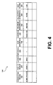
- FIG. 4 is a schematic diagram of the realm database table 324 located within the realm database 322 (FIG. 3).
- the realm database table 324 stores information required by the signaling proxy 314 (FIG. 3) to determine bandwidth availability, allocate bandwidth for transmission of multimedia packets, manage the allocated bandwidth and ensure that bandwidth quality and quantity is appropriate for transmission of multimedia packets.
- the realm database table 324 has an originating realm column 326, a part of realm column 328, a layer 2 column 332, an interface column 334, a sub-interface column 336, an address column 338, a maximum bandwidth column 342, an allocated bandwidth column 344 and a QoS score column 346. Within each column is a series of cells utilized to store information as described below.
- Cells within the originating realm column 326 store text names of sources of signaling messages and multimedia packet flows.
- the text names serve as keys to the realm database table 324.
- the text names can contain different types of characters and are limited in number of characters by the amount of space allocated within the realm database 322 for the text names.
- Examples of originating realms may include, the first private network 224, the second private network 234 and the third private network 244 of FIG. 2.
- Cells within the part of realm column 328 store text names that represent a location in which an originating realm is located.
- the part of realm may be a local area network (LAN).
- the part of realm may be a public data network.
- the originating realm is the first private network 224
- the part of realm may be the first aggregation realm 212.
- Cells within the layer 2 column 332 store an identification of a type of layer 2 networking that is being used by the first session director 203.
- the identification of the type of layer 2 networking is used to further define information stored within the sub-interface column 336.
- the interface column 334 indicates on which interface 302, 304 (FIG. 3) the realm is located.
- Cells within the sub-interface column 336 store numerical indicators that are used to provide layer 2 separation. Therefore, if more than one cell within the address column 338 has the same value stored therein, the sub-interface column 336 may be used to differentiate between the cells.
- the numerical indicator may represent an 802.1q VLAN tag.
- the numerical indicator may represent a PVC number.
- Cells within the address column 338 store addresses, such as IP addresses.
- each IP address is followed by a slash and a numerical representation of a maximum number of bits that may be used to identify an originating realm associated with the IP address. Therefore, when an IP address is provided by the signaling proxy 314 (FIG. 3), as is further explained below, for a source of a multimedia packet flow, the IP address is matched with entries stored within cells of the originating realm column 326, thereby determining a source of the multimedia packet flow.
- association between information stored within cells of the originating realm column 326, part of realm column 328, layer 2 column 332, interface column 334, sub-interface column 336, address column 338, maximum bandwidth column 342, allocated bandwidth column 344 and QoS score column 346 is indicated by the information being stored within cells located within the same row of the realm database table 324.
- Cells within the maximum bandwidth column 342 store numerical representations of amounts of bandwidth that can be used for multimedia packet flows originating from the originating realms. Preferably, there is one numerical representation of an amount of bandwidth that can be used for multimedia packet flows originating from one originating realm.
- the amount of bandwidth indicated within cells of the maximum bandwidth column 342 is an advisory limit specified by an administrator of the first session director 203, and is less than a physical bandwidth made available by the originating realm.
- an Acme Packet originating realm is allowed a maximum of an 800 kilobyte (KB) bandwidth for multimedia packet transmission to or from the Acme Packet originating realm.
- the actual physical bandwidth available for multimedia packet transmission may be much larger than the specified maximum bandwidth.
- Values for cells within the allocated bandwidth column 344 and the QoS score column 346 are dynamically determined when the first session director 203 is being used, as explained below.
- Cells within the allocated bandwidth column 344 store a numerical representation of total bandwidth that has been allocated for multimedia packet flows by the first session director 203, wherein one numerical representation is stored for each originating realm. It should be noted that the numerical representation is maintained in real-time as new multimedia packet flows are provisioned for by the first session director 203 or as multimedia packet flows are terminated by the first session director 203.
- Cells within the QoS score column 346 store a QoS score, as determined by the signaling proxy 314 (FIG. 3), which is a numerical representation of the bandwidth quality based on measured jitter, packet loss and latency of multimedia packet flows originating from the origination realm.
- the signaling proxy 314 FIG. 3
- the allocated bandwidth and QoS score Prior to use of the first session director 203 (FIG. 3), information, excluding the allocated bandwidth and QoS score, that is stored within the realm database table 324 is provided by the flow quality measurement engine 348 (FIG. 3) located within the first session director 203 (FIG. 3). Alternatively, the allocated bandwidth and QoS score are calculated by the signaling proxy 314 (FIG. 3) while the first session director 203 (FIG. 3) is in use. Further explanation of QoS score calculation is provided in detail below.
- FIG. 5 is a flowchart 350 providing an overview of functions performed via use of the first session director 203 of FIG. 3. Any process descriptions or blocks in flowcharts should be understood as representing modules, segments, or portions of code that include one or more executable instructions for implementing specific logical functions or steps in the process, and alternative implementations are included within the scope of the first exemplary embodiment of the invention in which functions may be executed out of order from that shown by figures or discussed herein, including substantially concurrently or in reverse order, depending on the functionality involved, as would be understood by those having ordinary skill in the art of the present invention.
- bandwidth is allocated for an originating realm. Allocation of bandwidth for the originating realm allows traversal of multimedia packet flows from a source located within the originating realm to the first session director 203 (FIG. 3). Bandwidth allocation is further described by the description of FIG. 6 provided below.
- Quality of the bandwidth allocated for the originating realm is determined to verify that current bandwidth quality is sufficient for the transmission of multimedia packets (block 362). If the bandwidth quality is sufficient for the transmission of multimedia packets, bandwidth is allocated for a part of realm (block 364). Quality of the bandwidth allocated for the part of realm is determined for transmission of multimedia packets (block 366). Functions described by block 364 and block 366 are repeated until there are no remaining part of realms associated with the originating realm (block 368).
- signaling packets associated with the multimedia packet flows are updated if necessary to reflect determined available bandwidth. Addresses of multimedia descriptors, such as but not limited to, source addresses and destination addresses, located within signaling packets are updated so that multimedia packets and signaling packets being transmitted from originating realms or part of realms are transmitted to the first session director 203 (FIG. 2) prior to transmission to a destination address.
- the signaling proxy 314 (FIG. 3) performs the updating of the multimedia descriptors.
- the updated signaling packet is transmitted from the signaling proxy 314 (FIG. 3) to the traffic manager 316 (FIG. 3).
- the traffic manager 316 (FIG. 3) then forwards the updated signaling packet to the second interface 304 (FIG. 3), (block 374), after which the updated signaling packet is transmitted to a destination of the updated signaling packet (block 376).
- a response to the transmitted updated signaling packet is received by the first session director 203 (block 378).
- the response arrives at the first interface 302 (FIG. 3) and travels to the signaling proxy 314 (FIG. 3) for analysis.
- the response could be either a positive response indicating that a multimedia packet flow may begin (e.g., SIP OK, H.323 Connect, MGCP MODIFY CONNECTION), or a negative acknowledgement (e.g., SIP NACK, H.323 Release Complete). If the response received by the first session director is a negative acknowledgement, the previously allocated bandwidth is de-allocated (block 382) by adding the reserved bandwidth back within the realm database 324 (FIG.
- a timeout period (e.g., MGCP Timeout) may also be considered a negative acknowledgement, wherein the signaling proxy 314 de-allocates previously allocated bandwidth if a response is not received by the first session director 203 after a predetermined period of time.
- bandwidth re-allocation is as follows. Assuming that a request for G.711 or G.729 is transmitted to a destination, an allocation of 80KB is made, and a SIP NACK is returned by the destination to the first session director. The allocated 80KB is then subtracted from the bandwidth value that was allocated for multimedia packet flows.
- bandwidth allocation is recomputed to reflect actual bandwidth to be utilized by multimedia packets, as described in the returned media descriptor (block 384).
- bandwidth allocation is recomputed to reflect actual bandwidth to be utilized by multimedia packets, as described in the returned media descriptor (block 384).
- the allocated bandwidth stored within the allocated bandwidth column 344 is reduced to reflect the actual bandwidth flow.
- FIG. 6 is a flowchart 390 further illustrating the step of allocating bandwidth for transmission of multimedia packets from a source to the first session director 203 of FIG. 3 (block 360, FIG. 5).
- a source address of the signaling message is extracted from the signaling packet.
- the source address may be found in a session description protocol (SDP) portion of INVITE and CREATE CONNECTION messages respectively.
- SDP session description protocol
- a measure of bandwidth for multimedia packet transmission is allocated for the source, wherein the measure of bandwidth is equivalent to a maximum measure of bandwidth accommodated for by a maximum supported type of bandwidth allowed by the source (block 394).
- a source may support numerous types of bandwidth, wherein a maximum supported type of bandwidth would be the type requiring the largest allocation of bandwidth.
- a maximum supported type of bandwidth would be the type requiring the largest allocation of bandwidth.
- an 80KB bandwidth may be reserved for voice communication.
- the measure of bandwidth for multimedia packet transmission that is allocated for the source is stored in the allocated bandwidth 344 column (FIG. 4) of the realm database table 324 (FIG. 4).
- the measure of bandwidth is stored within a cell of the allocated bandwidth 344 column (FIG. 4) that is within the same row as a cell, located within the address column 338 (FIG. 4), that has the address of the source stored therein.
- An originating realm of the signaling packet is determined by searching for the source address within the address column 338 (FIG. 4) of the realm database table 324 (FIG. 4) and determining the originating realm associated with the source address (block 396).
- the originating realm associated with the source address is stored within a cell of the originating realm column 326 (FIG. 4) that is within the same row of the realm database table (FIG. 4) as a cell within the address column 338 (FIG. 4) having the source address stored therein.
- the allocated bandwidth is compared to a maximum bandwidth allowed by the determined originating realm (block 398).
- the maximum bandwidth allowed by the determined originating realm is stored within a cell located within the maximum bandwidth column 342 (FIG. 4) of the realm database table 324 (FIG. 4) that is within the same row as the cell storing the determined originating realm. If the allocated bandwidth is smaller than the maximum bandwidth allowed, then bandwidth is available to allow a requested communication and the communication may be allowed (block 400). However, if the allocated bandwidth is larger than the maximum bandwidth allowed, bandwidth necessary for allowance of the requested communication is not available and the requested communication is not allowed (block 402).
- a lower bandwidth type of communication may be requested by the source of the signaling message, thereby determining if a lower bandwidth type of communication is acceptable.
- block 394 of FIG. 6 is replaced with allocating bandwidth for a lower supported category of bandwidth allowable by the source of the communication request.
- a G.711 call request may be downgraded to a G.729 call request.
- media descriptors also require modification to eliminate higher bandwidth options from being selected by a party answering the communication request.
- media descriptors located within the SDP (for SIP and MGCP) and/or H.245 (for H.323) would need to be modified.
- the bandwidth quality of the source may be determined by searching for a QoS score associated with the determined originating realm.
- the QoS score column 346 (FIG. 4) of the realm database 322 (FIG. 4) is searched for a QoS score that is stored within a cell located within the same row as the cell within the originating realm column 326 (FIG. 4) having the originating realm stored therein.
- a QoS score is a numerical representation of bandwidth quality based upon measured jitter, packet loss and latency of multimedia packet flows originating from an associated origination realm.
- QoS scores stored within the QoS score column 346 are periodically updated by the signaling proxy 314 (FIG. 3) after receipt of new values for jitter, packet loss and/or latency from the flow quality measurement engine 348 (FIG. 3).
- the flow quality measurement engine 348 (FIG. 3) may be programmed to perform periodic updates in accordance with an update schedule. After determining new jitter, packet loss and/or latency values, the flow quality measurement engine 348 (FIG. 3) transfers the value(s) to the signaling proxy 314 (FIG. 3), which may then update the QoS scores.
- a QoS score is computed that summarizes the three statistics into a single value.
- An example of a commercially available algorithm is VQmon® from Telchemy of Atlanta, GA, USA.
- the algorithm provided by VQmon® allows the entry of jitter, latency and packet loss values, after which a single VQmon® score is computed that may be used as the QoS score.
- the QoS score ranges from a value of zero (0), to a value of one (1).
- a QoS score of 1 represents that the current bandwidth quality associated with an originating realm is perfect, meaning that all bandwidth is available for transmission of multimedia packets and there is no measured jitter, latency or packet loss.
- An example of when a QoS score may be 1 is when there are no existing multimedia packet flows in an originating realm during an update period of the flow quality measurement engine 348 (FIG. 3).
- the signaling proxy 314 compares the determined QoS score to a default quality level required for transmission of multimedia packets from the source. As an example, if the determined QoS score for a LAN is a value of 0.7, the determined QoS score of 0.7 is compared to a default quality level requirement, which for exemplary purposes, is assumed to be 0.8. Since the determined QoS is less than the default level requirement, the multimedia packet flow from the source may not be transmitted via the allocated bandwidth.
- the determined QoS score for a LAN is a value of 0.9
- the determined QoS score of 0.9 is compared to a default quality level requirement, which for this example, is assumed to be 0.8. Since the determined QoS is more than the default level requirement, the multimedia packet flow from the source may be transmitted via the allocated bandwidth.
- a maximum supported type of bandwidth allowed by the part of realm is allocated.
- a part of realm associated with a signaling packet may be determined by reading a cell within the part of realm column 328 (FIG. 4) of the realm database table 324 (FIG. 4) that is located within the same row as a cell storing the previously determined originating realm.
- FIG. 4 there may be a part of realm maximum bandwidth column and a part of realm allocated bandwidth column located within the realm database table 324 (FIG. 4) for storage and comparison of the maximum supported bandwidth and allocated bandwidth, respectively.
- the bandwidth allocated for the part of realm is compared to a maximum bandwidth allowed by the determined part of realm (block 414). If the allocated bandwidth is smaller than the maximum bandwidth allowed, then bandwidth is available to allow the requested communication and the communication may be allowed (block 416). However, if the allocated bandwidth is larger than the maximum bandwidth allowed, bandwidth necessary for allowing the requested communication is not available and the requested communication is not allowed (block 418).
- a lower bandwidth type of communication if the allocated bandwidth for the part of realm is larger than the maximum bandwidth allowed, other types of communication may be requested by the part of realm, thereby determining if a lower bandwidth type of communication is acceptable.
- block 412 of FIG. 7 is replaced with allocating bandwidth for a lower supported category of bandwidth allowable by the part of realm.
- a G.711 call request may be downgraded to a G.729 call request.
- media descriptors located within the SDP (for SIP and MGCP) and/or H.245 (for H.323) also require modification to eliminate higher bandwidth options from being selected by a party answering the communication request.
- bandwidth quality of the bandwidth allocated for the part of realm is determined (block 366, FIG. 5).
- the bandwidth quality of the source may be determined by searching for the QoS score associated with the determined part of realm.
- the QoS score column 346 (FIG. 4) of the realm database 322 (FIG. 4) is searched for a QoS score that is associated with the part of realm.
- the signaling proxy 314 compares the determined QoS score to a default quality level required for transmission of multimedia packets from the part of realm. As stated above, allocation of bandwidth for the part of realm and determination of quality of the bandwidth allocated for the part of realm is then repeated until there are no remaining part of realms associated with the originating realm.
Landscapes
- Engineering & Computer Science (AREA)
- Computer Networks & Wireless Communication (AREA)
- Signal Processing (AREA)
- Multimedia (AREA)
- Business, Economics & Management (AREA)
- General Business, Economics & Management (AREA)
- Data Exchanges In Wide-Area Networks (AREA)
- Computer And Data Communications (AREA)
Claims (10)
- Sitzungsregler (203), mit:einem Paketklassifizierer (306); undeinem Signalisierungsproxy (314), das zum Zuweisen einer Bandbreite zum Annehmen einer Kommunikationssitzungsanfrage von einer Quelle (261, 271) konfiguriert ist,dadurch gekennzeichnet, dassder Sitzungsregler (203) angepasst ist, um sowohl die Paketflusskontrolle als auch die QoS-Paketflusszulassungskontrolle an einem gezwungenen Punkt zu verwalten, der proximal zu der Schnittstelle zwischen einem öffentlichen Datennetzwerk-Einwahlknoten, im Weiteren als "PDN POP" bezeichnet, und einem oder mehreren anderen Netzwerken vor dem Eingang von Paketen in ein Netzwerk liegt, und wenn Pakete das PDP POP verlassen, sofern dies erforderlich ist,der Paketklassifizierer (306) angepasst ist, um festzustellen, ob ein von dem Sitzungsregler (203) empfangenes Paket ein Echtzeit-Regelprotokollpaket, im Weiteren als "RTCP" bezeichnet, oder ein Echtzeit-Protokollpaket, im Weiteren als "RTP" bezeichnet, ist, unddas Signalisierungsproxy (314) eine Realm-Datenbank (322) verwendet und angepasst ist, um die Bandbreitenverfügbarkeit zu bestimmen, eine Bandbreite für die Übertragung von Multimediapaketen zuzuweisen, die zugewiesene Bandbreite zu verwalten und sicherzustellen, dass die Qualität und Quantität der Bandbreite für die Übertragung von Multimediapaketen geeignet ist.
- Sitzungsregler (203) nach Anspruch 1, wobei das Signalisierungsproxy (314) auf eine Datenbanktabelle (324) zugreift, die einen Datensatz mit mindestens einem der folgenden Felder aufweist: ein Quell-Realm (326), ein Teil-Realm (328), eine Adresse (338), eine maximale Bandbreite (342), eine zugewiesene Bandbreite (344) und ein QoS-Wert (346).
- Sitzungsregler (203) nach Anspruch 1, wobei der Paketklassifizierer (306) ausgebildet ist, um die Signalisierungspakete zu untersuchen, Informationen aus den Echtzeit-Transportkontrollprotokollpaketen zu extrahieren und die Echtzeit-Transportkontrollprotokollpakete, die keine nutzbaren Informationen enthalten, an einen Prozessor für fallen gelassene Pakete (312) innerhalb des Sitzungsreglers (203) weiterzuleiten.
- Sitzungsregler (203) nach Anspruch 3, wobei der Prozessor für fallen gelassene Pakete (312) eine Quelle der an den Sitzungsregler (203) übermittelten Signalisierungspakete identifiziert.
- Sitzungsregler (203) nach Anspruch 1, wobei die Kommunikationssitzungsanfrage eine Sitzungseinleitungsprotokollanfrage aufweist.
- Sitzungsregler (203) nach Anspruch 1, wobei das Signalisierungsproxy (314) eine Bandbreite zuweist, indem eine maximale unterstützte Bandbreite (342) der Quelle (261, 271) bestimmt und eine zugewiesene Bandbreite (344), die an die maximal unterstützte Bandbreite (342) angepasst ist, zugewiesen wird; sicherstellt, dass die zugewiesene Bandbreite (344) für eine Übertragung von Multimediapaketen von der Quelle (261, 271) an den Sitzungsregler (203) durch Vergleichen der zugewiesenen Bandbreite (344) mit einer maximalen Bandbreite, die von einem Quell-Realm (152) zugelassen wird, geeignet ist, wobei das Quell-Realm (152) die Quelle (261, 271) umfasst; und sicherstellt, dass das QoS der zugewiesenen Bandbreite (344) geeignet ist, um den Fluss bereitzustellen, indem ein QoS-Wert (346) gewonnen wird, der mit dem Quell-Realm (152) verbunden ist, wobei der QoS-Wert (152) mit einem vorbestimmten Qualitätsniveau der Bandbreite verglichen wird, welches für eine Übertragung von Multimediapaketen von der Quelle (261, 271) erforderlich ist, wobei eine Übertragung der Multimediapakete zugelassen wird, wenn der QoS-Wert (346) das vorbestimmte Qualitätsniveau der Bandbreite überschreitet, und ansonsten eine Übertragung der Multimediapakete auf verhindert wird.
- Sitzungsregler (203) nach Anspruch 6, wobei der QoS-Wert (346) eine numerische Darstellung der Qualität der Bandbreite basierend auf gemessenem Jitter, Paketverlust und Latenzzeit von von dem Quell-Realm (152) stammenden Multimediapaketflüssen ist.
- Verfahren zum Bereitstellen einer Sitzungszulassungsregelung, mit den Schritten:Empfangen einer Kommunikationssitzungsanfrage von einer Quelle, wobei die Kommunikationssitzungsanfrage Indizien einer gewünschten Bandbreite für eine vorgeschlagene Kommunikationssitzung aufweist;Generieren einer zugewiesenen Bandbreite zum Annehmen der Kommunikationssitzungsanfrage (360);Sicherstellen, dass die zugewiesene Bandbreite für die Übertragung von Multimediapaketen (364) geeignet ist; undSicherstellen, dass ein QoS der zugewiesenen Bandbreite zum Bereitstellen eines Flusses der Multimediapakete über die zugewiesene Bandbreite (366) geeignet ist;dadurch gekennzeichnet, dassder Schritt des Empfangens einer Kommunikationssitzungsanfrage an einer Schnittstelle zwischen einem öffentlichen Datennetzwerk-Einwahlknoten, im Weiteren als "PDN POP" bezeichnet, und einem oder mehreren anderen Netzwerken vor dem Eingang von Paketen in ein Netzwerk und dann ausgeführt wird, wenn Pakete das PDN POP verlassen, und wobei der Schritt des Sicherstellens der zugewiesenen Bandbreite, die für die Übertragung von Multimediapaketen geeignet ist, weiterhin Folgendes aufweist:Vergleichen der zugewiesenen Bandbreite mit einer maximalen Bandbreite, die von dem Quell-Realm (398) erlaubt wird, in Übereinstimmung mit einem Datensatz in einer Realm-Datenbank (322), wobei der Datensatz mindestens eines der folgenden Felder aufweist: ein Quell-Realm (326), ein Teil-Realm (328), ein Schichtprotokoll (332), einen Schnittstellenidentifizierer (334), einen Sub-Schnittstellenidentifizierer (336), eine Adresse (338), eine maximale Bandbreite (342), eine zugewiesene Bandbreite (344), und einen QoS-Wert (346);Übertragen der Multimediapakete, wenn die zugewiesene Bandbreite (344) kleiner ist als die maximale Bandbreite (342), die von dem Datensatz erlaubt wird, und ansonstenVerhindern der Übertragung der Multimediapakete.
- Verfahren nach Anspruch 8, wobei der Schritt des Empfangens einer Kommunikationssitzungsanfrage das Bestätigen der Anfrage in Übereinstimmung mit einer Sitzungseinleitungsprotokollanfrage aufweist.
- Verfahren nach Anspruch 8, wobei der Schritt des Sicherstellens, dass ein QoS der zugewiesenen Bandbreite geeignet ist, um einen Fluss bereitzustellen, die folgenden Schritte aufweist:Gewinnen eines QoS-Werts, der mit einem Quell-Realm verbunden ist,Vergleichen des QoS-Werts mit einem vorbestimmten Qualitätsniveau der Bandbreite, welches für eine Übertragung von Multimediapaketen von der Quelle (362) erforderlich ist,Gestatten einer Übertragung der Multimediapakete, wenn der QoS-Wert das Qualitätsniveau der vorbestimmten Bandbreite (374) überschreitet, und ansonsten Verhindern der Übertragung der Multimediapakete (382).
Applications Claiming Priority (2)
| Application Number | Priority Date | Filing Date | Title |
|---|---|---|---|
| US198852 | 1998-11-24 | ||
| US10/198,852 US7151781B2 (en) | 2002-07-19 | 2002-07-19 | System and method for providing session admission control |
Publications (2)
| Publication Number | Publication Date |
|---|---|
| EP1383285A1 EP1383285A1 (de) | 2004-01-21 |
| EP1383285B1 true EP1383285B1 (de) | 2007-01-24 |
Family
ID=29780219
Family Applications (1)
| Application Number | Title | Priority Date | Filing Date |
|---|---|---|---|
| EP03016389A Expired - Lifetime EP1383285B1 (de) | 2002-07-19 | 2003-07-21 | System und Verfahren für Sitzungszulassungssteuerung |
Country Status (5)
| Country | Link |
|---|---|
| US (2) | US7151781B2 (de) |
| EP (1) | EP1383285B1 (de) |
| JP (1) | JP4390498B2 (de) |
| AT (1) | ATE352931T1 (de) |
| DE (1) | DE60311364T2 (de) |
Families Citing this family (87)
| Publication number | Priority date | Publication date | Assignee | Title |
|---|---|---|---|---|
| US6963545B1 (en) | 1998-10-07 | 2005-11-08 | At&T Corp. | Voice-data integrated multiaccess by self-reservation and stabilized aloha contention |
| US6747959B1 (en) | 1998-10-07 | 2004-06-08 | At&T Corp. | Voice data integrated mulitaccess by self-reservation and blocked binary tree resolution |
| US6950397B1 (en) | 2000-07-14 | 2005-09-27 | At&T Corp. | RSVP/SBM based side-stream session setup, modification, and teardown for QoS-driven wireless lans |
| US6804222B1 (en) | 2000-07-14 | 2004-10-12 | At&T Corp. | In-band Qos signaling reference model for QoS-driven wireless LANs |
| US7756092B1 (en) | 2000-07-14 | 2010-07-13 | At&T Intellectual Property Ii, L.P. | In-band QoS signaling reference model for QoS-driven wireless LANs connected to one or more networks |
| US7068632B1 (en) | 2000-07-14 | 2006-06-27 | At&T Corp. | RSVP/SBM based up-stream session setup, modification, and teardown for QOS-driven wireless LANs |
| US7068633B1 (en) | 2000-07-14 | 2006-06-27 | At&T Corp. | Enhanced channel access mechanisms for QoS-driven wireless lans |
| US7151762B1 (en) | 2000-07-14 | 2006-12-19 | At&T Corp. | Virtual streams for QoS-driven wireless LANs |
| US7039032B1 (en) | 2000-07-14 | 2006-05-02 | At&T Corp. | Multipoll for QoS-Driven wireless LANs |
| US7031287B1 (en) | 2000-07-14 | 2006-04-18 | At&T Corp. | Centralized contention and reservation request for QoS-driven wireless LANs |
| US7151781B2 (en) * | 2002-07-19 | 2006-12-19 | Acme Packet, Inc. | System and method for providing session admission control |
| KR100475186B1 (ko) * | 2002-12-02 | 2005-03-10 | 삼성전자주식회사 | 접속 설정 프로토콜을 이용한 단말 장치의 등록 방법 |
| US20040148391A1 (en) * | 2003-01-11 | 2004-07-29 | Lake Shannon M | Cognitive network |
| US7684432B2 (en) | 2003-05-15 | 2010-03-23 | At&T Intellectual Property I, L.P. | Methods of providing data services over data networks and related data networks, data service providers, routing gateways and computer program products |
| US8174970B2 (en) | 2003-05-15 | 2012-05-08 | At&T Intellectual Property I, L.P. | Methods of implementing dynamic QoS and/or bandwidth provisioning and related data networks, data service providers, routing gateways, and computer program products |
| US7573906B2 (en) * | 2003-05-15 | 2009-08-11 | At&T Intellectual Property I, L.P. | Methods, computer program products, and systems for managing quality of service in a communication network for applications |
| WO2005004370A2 (en) * | 2003-06-28 | 2005-01-13 | Geopacket Corporation | Quality determination for packetized information |
| US7643442B1 (en) * | 2003-06-30 | 2010-01-05 | Cisco Systems, Inc. | Dynamic QoS configuration based on transparent processing of session initiation messages |
| US7701854B2 (en) * | 2003-11-17 | 2010-04-20 | International Business Machines Corporation | Differentiated handling of SIP messages for VoIP call control |
| US8312145B2 (en) * | 2003-12-22 | 2012-11-13 | Rockstar Consortium US L.P. | Traffic engineering and bandwidth management of bundled links |
| US7788357B2 (en) * | 2004-01-23 | 2010-08-31 | Camiant, Inc. | Policy-based admission control and bandwidth reservation for future sessions |
| US20050180426A1 (en) * | 2004-02-18 | 2005-08-18 | Yoshifumi Sakata | Network resource-reserving apparatus and method |
| US7369558B1 (en) * | 2004-04-13 | 2008-05-06 | Sprint Communications Company L.P. | ATM connection allocation in ATM networks |
| US7379461B2 (en) * | 2004-04-26 | 2008-05-27 | Alcatel Lucent | System and method for indicating network quality of service capability as a presence attribute of an end-user |
| US7403544B2 (en) * | 2004-06-04 | 2008-07-22 | Broadcom Corporation | VoIP WLAN conference calling via home wireless routers |
| US8370888B2 (en) * | 2004-06-22 | 2013-02-05 | University Of Southern California | Hydra: high-performance data recording architecture for streaming media |
| US7545788B2 (en) | 2004-08-20 | 2009-06-09 | At&T Intellectual Property I, L.P. | Methods, systems, and computer program products for modifying bandwidth and/or quality of service in a core network |
| US7764605B2 (en) * | 2004-10-07 | 2010-07-27 | Genband Inc. | Methods and systems for measurement-based call admission control in a media gateway |
| EP1800440A1 (de) * | 2004-10-14 | 2007-06-27 | Telefonaktiebolaget LM Ericsson (publ) | Router und verfahren zum auffrischen von dienstqualitätsreservierung |
| US7466714B2 (en) * | 2004-12-08 | 2008-12-16 | At&T Intellectual Property I, L.P. | Methods, systems, and computer program products for operating a communication network by dividing the network into multiple zones and defining policies that specify allowable communications between the zones |
| US8194640B2 (en) * | 2004-12-31 | 2012-06-05 | Genband Us Llc | Voice over IP (VoIP) network infrastructure components and method |
| DE102005001956B4 (de) * | 2005-01-14 | 2006-11-09 | Infineon Technologies Ag | Verfahren und Vorrichtung zur Datenübertragung mit einer DSL-Technik |
| DE102005003016B4 (de) * | 2005-01-21 | 2006-10-26 | Infineon Technologies Ag | Verfahren und Vorrichtungen zur Datenübertragung |
| JPWO2006093221A1 (ja) * | 2005-03-04 | 2008-08-07 | ヒューレット−パッカード デベロップメント カンパニー エル.ピー. | 伝送制御装置およびその方法 |
| CN1842066A (zh) * | 2005-03-29 | 2006-10-04 | 鸿富锦精密工业(深圳)有限公司 | 网络通信设备及使用该网络通信设备的传输系统 |
| US7975283B2 (en) * | 2005-03-31 | 2011-07-05 | At&T Intellectual Property I, L.P. | Presence detection in a bandwidth management system |
| US8024438B2 (en) * | 2005-03-31 | 2011-09-20 | At&T Intellectual Property, I, L.P. | Methods, systems, and computer program products for implementing bandwidth management services |
| US8098582B2 (en) * | 2005-03-31 | 2012-01-17 | At&T Intellectual Property I, L.P. | Methods, systems, and computer program products for implementing bandwidth control services |
| US8306033B2 (en) * | 2005-03-31 | 2012-11-06 | At&T Intellectual Property I, L.P. | Methods, systems, and computer program products for providing traffic control services |
| US8335239B2 (en) | 2005-03-31 | 2012-12-18 | At&T Intellectual Property I, L.P. | Methods, systems, and devices for bandwidth conservation |
| US20070291734A1 (en) * | 2005-05-27 | 2007-12-20 | Medhavi Bhatia | Methods and Apparatus for Multistage Routing of Packets Using Call Templates |
| KR20060123974A (ko) * | 2005-05-30 | 2006-12-05 | 삼성전자주식회사 | 이종 시스템들간 서비스 연동 방법 |
| US7502320B2 (en) * | 2005-07-06 | 2009-03-10 | Cisco Technology, Inc. | Method and apparatus for network-based admission control using path-coupled quality of service signaling |
| US8701148B2 (en) | 2005-09-01 | 2014-04-15 | At&T Intellectual Property I, L.P. | Methods, systems, and devices for bandwidth conservation |
| US8104054B2 (en) | 2005-09-01 | 2012-01-24 | At&T Intellectual Property I, L.P. | Methods, systems, and devices for bandwidth conservation |
| US7792025B2 (en) * | 2005-10-11 | 2010-09-07 | Alcatel Lucent | Multi-service session admission control |
| FI20051061A0 (fi) * | 2005-10-21 | 2005-10-21 | Nokia Corp | Vertaisyhteyden luominen |
| EP1808993A3 (de) * | 2005-12-08 | 2007-08-01 | Electronics and Telecommunications Research Institute | Übertragungsvorrichtung mit einer Vielzahl von Netzwerkschnittstellen und entsprechendes Übertragungsverfahren |
| US9060047B2 (en) | 2005-12-21 | 2015-06-16 | Genband Us Llc | Media stream management |
| US7865612B2 (en) * | 2006-01-31 | 2011-01-04 | Genband Us Llc | Method and apparatus for partitioning resources within a session-over-internet-protocol (SoIP) session controller |
| US7860990B2 (en) * | 2006-01-31 | 2010-12-28 | Genband Us Llc | Session data records and related alarming within a session over internet protocol (SOIP) network |
| US7861003B2 (en) | 2006-01-31 | 2010-12-28 | Genband Us Llc | Adaptive feedback for session over internet protocol |
| CN100396009C (zh) * | 2006-02-23 | 2008-06-18 | 华为技术有限公司 | 带宽控制方法、系统、接入控制设备、用户档案管理设备 |
| US8509218B2 (en) * | 2006-02-28 | 2013-08-13 | Genband Us Llc | Prioritization within a session over internet protocol (SOIP) network |
| US8259706B2 (en) * | 2006-02-28 | 2012-09-04 | Genband Us Llc | Multistage prioritization of packets within a session over internet protocol (SOIP) network |
| US8204043B2 (en) * | 2006-02-28 | 2012-06-19 | Genband Us Llc | Quality of service prioritization of internet protocol packets using session-aware components |
| US8363555B2 (en) * | 2006-10-25 | 2013-01-29 | Cisco Technology, Inc. | Monitoring internet protocol (IP) telephony signaling links |
| KR100832537B1 (ko) * | 2006-12-01 | 2008-05-27 | 한국전자통신연구원 | 네트워크 대역폭 상태에 따라 전송량을 가변하는멀티미디어 데이터 스트리밍 서버 및 방법 |
| US7626929B2 (en) * | 2006-12-28 | 2009-12-01 | Genband Inc. | Methods and apparatus for predictive call admission control within a media over internet protocol network |
| US7774481B2 (en) * | 2006-12-29 | 2010-08-10 | Genband Us Llc | Methods and apparatus for implementing a pluggable policy module within a session over internet protocol network |
| JP4844425B2 (ja) * | 2007-02-15 | 2011-12-28 | ソニー株式会社 | 帯域要求システム、帯域要求装置、クライアント機器、帯域要求方法、コンテンツ再生方法およびプログラム |
| US9276776B2 (en) * | 2007-09-28 | 2016-03-01 | Genband Us Llc | Methods and apparatus for bandwidth management within a media over internet protocol network based on a session description |
| US7912062B2 (en) | 2007-09-28 | 2011-03-22 | Genband Us Llc | Methods and apparatus for managing addresses related to virtual partitions of a session exchange device |
| US8862706B2 (en) | 2007-12-14 | 2014-10-14 | Nant Holdings Ip, Llc | Hybrid transport—application network fabric apparatus |
| US7904602B2 (en) * | 2008-02-05 | 2011-03-08 | Raptor Networks Technology, Inc. | Distributed computing bus |
| US9106592B1 (en) * | 2008-05-18 | 2015-08-11 | Western Digital Technologies, Inc. | Controller and method for controlling a buffered data transfer device |
| US8339959B1 (en) | 2008-05-20 | 2012-12-25 | Juniper Networks, Inc. | Streamlined packet forwarding using dynamic filters for routing and security in a shared forwarding plane |
| US9237086B2 (en) * | 2008-05-30 | 2016-01-12 | Genband Us Llc | Methods and apparatus for network traffic distribution based on random number values |
| US8955107B2 (en) * | 2008-09-12 | 2015-02-10 | Juniper Networks, Inc. | Hierarchical application of security services within a computer network |
| US7921212B2 (en) * | 2008-10-14 | 2011-04-05 | At&T Intellectual Property I, L.P. | Methods and apparatus to allocate bandwidth between video and non-video services in access networks |
| US8040808B1 (en) | 2008-10-20 | 2011-10-18 | Juniper Networks, Inc. | Service aware path selection with a network acceleration device |
| TWI403197B (zh) * | 2009-12-21 | 2013-07-21 | Gemtek Technolog Co Ltd | In the wireless broadband network transmission of multimedia streaming user platform, communication systems and methods |
| US8868700B2 (en) | 2010-12-28 | 2014-10-21 | Nant Holdings Ip, Llc | Distributed network interfaces for application cloaking and spoofing |
| US8503298B2 (en) * | 2011-05-24 | 2013-08-06 | International Business Machines Corporation | Applying quality aware volume reduction to communication networks |
| US9251535B1 (en) | 2012-01-05 | 2016-02-02 | Juniper Networks, Inc. | Offload of data transfer statistics from a mobile access gateway |
| US8549570B2 (en) * | 2012-02-23 | 2013-10-01 | Ericsson Television Inc. | Methods and apparatus for managing network resources used by multimedia streams in a virtual pipe |
| TWI590631B (zh) * | 2012-03-15 | 2017-07-01 | 微軟技術授權有限責任公司 | 無線網路上的多模態通信優先性 |
| EP2728827A1 (de) | 2012-10-31 | 2014-05-07 | British Telecommunications public limited company | Kommunikationsnetzwerk zur Verbindung zweier Netzwerkknoten unter Verwendung eines Tunnels |
| KR102119112B1 (ko) * | 2013-09-17 | 2020-06-29 | 삼성전자 주식회사 | 트래픽 품질 제어 방법 및 장치 |
| US10291503B2 (en) * | 2013-09-26 | 2019-05-14 | Taiwan Semiconductor Manufacturing Co., Ltd. | File block placement in a distributed network |
| US9917728B2 (en) | 2014-01-14 | 2018-03-13 | Nant Holdings Ip, Llc | Software-based fabric enablement |
| US10212101B2 (en) | 2014-01-14 | 2019-02-19 | Nant Holdings Ip, Llc | Low level provisioning of network fabrics |
| US10447545B1 (en) * | 2014-12-23 | 2019-10-15 | Amazon Technologies, Inc. | Communication port identification |
| US9516552B2 (en) | 2015-01-28 | 2016-12-06 | International Business Machines Corporation | Ensuring quality of bandwidth in a Wi-Fi connection to an internet access point |
| US11128536B2 (en) | 2018-10-04 | 2021-09-21 | Sandvine Corporation | System and method for intent based traffic management |
| EP3920487B1 (de) | 2020-06-04 | 2024-08-07 | Sandvine Corporation | System und verfahren zur erfahrungsqualitätsverwaltung |
| US11516291B2 (en) * | 2020-09-29 | 2022-11-29 | Cohesity, Inc. | Secure communications of storage tenants that share a storage cluster system |
Family Cites Families (12)
| Publication number | Priority date | Publication date | Assignee | Title |
|---|---|---|---|---|
| US5784358A (en) * | 1994-03-09 | 1998-07-21 | Oxford Brookes University | Broadband switching network with automatic bandwidth allocation in response to data cell detection |
| US6094431A (en) * | 1995-11-30 | 2000-07-25 | Kabushiki Kaisha Toshiba | Node device and network resource reservation method for data packet transfer using ATM networks |
| US6154465A (en) * | 1998-10-06 | 2000-11-28 | Vertical Networks, Inc. | Systems and methods for multiple mode voice and data communications using intelligenty bridged TDM and packet buses and methods for performing telephony and data functions using the same |
| US6714987B1 (en) | 1999-11-05 | 2004-03-30 | Nortel Networks Limited | Architecture for an IP centric distributed network |
| US6980526B2 (en) * | 2000-03-24 | 2005-12-27 | Margalla Communications, Inc. | Multiple subscriber videoconferencing system |
| EP1148688A1 (de) | 2000-04-20 | 2001-10-24 | Telefonaktiebolaget L M Ericsson (Publ) | Vorrichtung und Verfahren mit einem Proxy |
| US20020016937A1 (en) * | 2000-08-02 | 2002-02-07 | Henry Houh | Method and apparatus for utilizing a network processor as part of a test system |
| US6894991B2 (en) * | 2000-11-30 | 2005-05-17 | Verizon Laboratories Inc. | Integrated method for performing scheduling, routing and access control in a computer network |
| US7072303B2 (en) * | 2000-12-11 | 2006-07-04 | Acme Packet, Inc. | System and method for assisting in controlling real-time transport protocol flow through multiple networks |
| US6956857B2 (en) * | 2001-09-24 | 2005-10-18 | Lucent Technologies Inc. | Guaranteed admission and incremental bandwidth allocation in a packet network |
| US20050002405A1 (en) * | 2001-10-29 | 2005-01-06 | Hanzhong Gao | Method system and data structure for multimedia communications |
| US7151781B2 (en) * | 2002-07-19 | 2006-12-19 | Acme Packet, Inc. | System and method for providing session admission control |
-
2002
- 2002-07-19 US US10/198,852 patent/US7151781B2/en not_active Expired - Lifetime
-
2003
- 2003-07-21 EP EP03016389A patent/EP1383285B1/de not_active Expired - Lifetime
- 2003-07-21 DE DE60311364T patent/DE60311364T2/de not_active Expired - Lifetime
- 2003-07-21 AT AT03016389T patent/ATE352931T1/de not_active IP Right Cessation
- 2003-07-22 JP JP2003277596A patent/JP4390498B2/ja not_active Expired - Lifetime
-
2006
- 2006-11-17 US US11/560,970 patent/US7912088B2/en not_active Expired - Lifetime
Also Published As
| Publication number | Publication date |
|---|---|
| DE60311364D1 (de) | 2007-03-15 |
| DE60311364T2 (de) | 2007-11-15 |
| ATE352931T1 (de) | 2007-02-15 |
| JP4390498B2 (ja) | 2009-12-24 |
| JP2004135279A (ja) | 2004-04-30 |
| US20070076603A1 (en) | 2007-04-05 |
| EP1383285A1 (de) | 2004-01-21 |
| US7151781B2 (en) | 2006-12-19 |
| US20040013119A1 (en) | 2004-01-22 |
| US7912088B2 (en) | 2011-03-22 |
Similar Documents
| Publication | Publication Date | Title |
|---|---|---|
| US7912088B2 (en) | System and method for providing session admission control | |
| US6449251B1 (en) | Packet mapper for dynamic data packet prioritization | |
| US7397763B2 (en) | Admissions control in a connectionless communications network | |
| US6760309B1 (en) | Method of dynamic prioritization of time sensitive packets over a packet based network | |
| US20030152096A1 (en) | Intelligent no packet loss networking | |
| KR100461728B1 (ko) | 라우터를 통한 DiffServ 기반 VoIP QoS제공 방법 | |
| CN101159675B (zh) | 在ip多媒体子系统中实现提高用户服务质量的方法 | |
| EP1902553B1 (de) | Anordnung und verfahren im bezug auf die handhabung von ip-verkehr | |
| US20060268692A1 (en) | Transmission of electronic packets of information of varying priorities over network transports while accounting for transmission delays | |
| WO2009146621A1 (zh) | 数据处理方法及宽带网络网关、策略控制器和接入设备 | |
| JP2006506845A (ja) | ルータにおけるパケットに対し論理リンクを選択する方法 | |
| CN1819547B (zh) | 数据传送装置 | |
| Shaikh et al. | End-to-end testing of IP QoS mechanisms | |
| JP2004241835A (ja) | 品質保証型データストリームを転送するための受付判定方法、閉域ip網、そのプログラム | |
| Wood et al. | Network quality of service for the enterprise: A broad overview | |
| Ram et al. | Admission control by implicit signaling in support of voice over IP over ADSL | |
| KR100621215B1 (ko) | 차등화 서비스(DiffServ) 기반 멀티미디어 서비스QoS 제공 시스템 및 방법 | |
| CN1881893B (zh) | 一种应用于QoS信令点之间的流控系统及方法 | |
| Batalla | OF TECHNOLOGY | |
| Zhuang | End to End Quality of Service in UMTS Systems | |
| Farooq et al. | QoS Mechanisms in NGN | |
| Klampfer et al. | Influences of Classical and Hybrid Queuing Mechanisms on VoIP’s QoS Properties | |
| Dreibholz et al. | An advanced QoS protocol for mass content | |
| Malhan et al. | Analysis of quality of services (QOS) on converged architecture | |
| Swanepoel | Network simulation for the effective extraction of IP network statistics |
Legal Events
| Date | Code | Title | Description |
|---|---|---|---|
| PUAI | Public reference made under article 153(3) epc to a published international application that has entered the european phase |
Free format text: ORIGINAL CODE: 0009012 |
|
| AK | Designated contracting states |
Kind code of ref document: A1 Designated state(s): AT BE BG CH CY CZ DE DK EE ES FI FR GB GR HU IE IT LI LU MC NL PT RO SE SI SK TR |
|
| AX | Request for extension of the european patent |
Extension state: AL LT LV MK |
|
| 17P | Request for examination filed |
Effective date: 20040515 |
|
| 17Q | First examination report despatched |
Effective date: 20040713 |
|
| AKX | Designation fees paid |
Designated state(s): AT BE BG CH CY CZ DE DK EE ES FI FR GB GR HU IE IT LI LU MC NL PT RO SE SI SK TR |
|
| GRAP | Despatch of communication of intention to grant a patent |
Free format text: ORIGINAL CODE: EPIDOSNIGR1 |
|
| GRAS | Grant fee paid |
Free format text: ORIGINAL CODE: EPIDOSNIGR3 |
|
| GRAA | (expected) grant |
Free format text: ORIGINAL CODE: 0009210 |
|
| AK | Designated contracting states |
Kind code of ref document: B1 Designated state(s): AT BE BG CH CY CZ DE DK EE ES FI FR GB GR HU IE IT LI LU MC NL PT RO SE SI SK TR |
|
| PG25 | Lapsed in a contracting state [announced via postgrant information from national office to epo] |
Ref country code: CH Free format text: LAPSE BECAUSE OF FAILURE TO SUBMIT A TRANSLATION OF THE DESCRIPTION OR TO PAY THE FEE WITHIN THE PRESCRIBED TIME-LIMIT Effective date: 20070124 Ref country code: AT Free format text: LAPSE BECAUSE OF FAILURE TO SUBMIT A TRANSLATION OF THE DESCRIPTION OR TO PAY THE FEE WITHIN THE PRESCRIBED TIME-LIMIT Effective date: 20070124 Ref country code: DK Free format text: LAPSE BECAUSE OF FAILURE TO SUBMIT A TRANSLATION OF THE DESCRIPTION OR TO PAY THE FEE WITHIN THE PRESCRIBED TIME-LIMIT Effective date: 20070124 Ref country code: NL Free format text: LAPSE BECAUSE OF FAILURE TO SUBMIT A TRANSLATION OF THE DESCRIPTION OR TO PAY THE FEE WITHIN THE PRESCRIBED TIME-LIMIT Effective date: 20070124 Ref country code: FI Free format text: LAPSE BECAUSE OF FAILURE TO SUBMIT A TRANSLATION OF THE DESCRIPTION OR TO PAY THE FEE WITHIN THE PRESCRIBED TIME-LIMIT Effective date: 20070124 Ref country code: LI Free format text: LAPSE BECAUSE OF FAILURE TO SUBMIT A TRANSLATION OF THE DESCRIPTION OR TO PAY THE FEE WITHIN THE PRESCRIBED TIME-LIMIT Effective date: 20070124 Ref country code: SI Free format text: LAPSE BECAUSE OF FAILURE TO SUBMIT A TRANSLATION OF THE DESCRIPTION OR TO PAY THE FEE WITHIN THE PRESCRIBED TIME-LIMIT Effective date: 20070124 |
|
| REG | Reference to a national code |
Ref country code: GB Ref legal event code: FG4D |
|
| REG | Reference to a national code |
Ref country code: CH Ref legal event code: EP |
|
| REG | Reference to a national code |
Ref country code: IE Ref legal event code: FG4D |
|
| REF | Corresponds to: |
Ref document number: 60311364 Country of ref document: DE Date of ref document: 20070315 Kind code of ref document: P |
|
| PG25 | Lapsed in a contracting state [announced via postgrant information from national office to epo] |
Ref country code: SE Free format text: LAPSE BECAUSE OF FAILURE TO SUBMIT A TRANSLATION OF THE DESCRIPTION OR TO PAY THE FEE WITHIN THE PRESCRIBED TIME-LIMIT Effective date: 20070424 |
|
| PG25 | Lapsed in a contracting state [announced via postgrant information from national office to epo] |
Ref country code: BG Free format text: LAPSE BECAUSE OF EXPIRATION OF PROTECTION Effective date: 20070425 |
|
| PG25 | Lapsed in a contracting state [announced via postgrant information from national office to epo] |
Ref country code: ES Free format text: LAPSE BECAUSE OF FAILURE TO SUBMIT A TRANSLATION OF THE DESCRIPTION OR TO PAY THE FEE WITHIN THE PRESCRIBED TIME-LIMIT Effective date: 20070505 |
|
| ET | Fr: translation filed | ||
| PG25 | Lapsed in a contracting state [announced via postgrant information from national office to epo] |
Ref country code: PT Free format text: LAPSE BECAUSE OF FAILURE TO SUBMIT A TRANSLATION OF THE DESCRIPTION OR TO PAY THE FEE WITHIN THE PRESCRIBED TIME-LIMIT Effective date: 20070625 |
|
| REG | Reference to a national code |
Ref country code: CH Ref legal event code: PL |
|
| NLV1 | Nl: lapsed or annulled due to failure to fulfill the requirements of art. 29p and 29m of the patents act | ||
| PG25 | Lapsed in a contracting state [announced via postgrant information from national office to epo] |
Ref country code: SK Free format text: LAPSE BECAUSE OF FAILURE TO SUBMIT A TRANSLATION OF THE DESCRIPTION OR TO PAY THE FEE WITHIN THE PRESCRIBED TIME-LIMIT Effective date: 20070124 |
|
| PLBE | No opposition filed within time limit |
Free format text: ORIGINAL CODE: 0009261 |
|
| STAA | Information on the status of an ep patent application or granted ep patent |
Free format text: STATUS: NO OPPOSITION FILED WITHIN TIME LIMIT |
|
| 26N | No opposition filed |
Effective date: 20071025 |
|
| PG25 | Lapsed in a contracting state [announced via postgrant information from national office to epo] |
Ref country code: BE Free format text: LAPSE BECAUSE OF FAILURE TO SUBMIT A TRANSLATION OF THE DESCRIPTION OR TO PAY THE FEE WITHIN THE PRESCRIBED TIME-LIMIT Effective date: 20070124 Ref country code: CZ Free format text: LAPSE BECAUSE OF FAILURE TO SUBMIT A TRANSLATION OF THE DESCRIPTION OR TO PAY THE FEE WITHIN THE PRESCRIBED TIME-LIMIT Effective date: 20070124 Ref country code: RO Free format text: LAPSE BECAUSE OF FAILURE TO SUBMIT A TRANSLATION OF THE DESCRIPTION OR TO PAY THE FEE WITHIN THE PRESCRIBED TIME-LIMIT Effective date: 20070124 |
|
| PG25 | Lapsed in a contracting state [announced via postgrant information from national office to epo] |
Ref country code: MC Free format text: LAPSE BECAUSE OF NON-PAYMENT OF DUE FEES Effective date: 20070731 Ref country code: GR Free format text: LAPSE BECAUSE OF FAILURE TO SUBMIT A TRANSLATION OF THE DESCRIPTION OR TO PAY THE FEE WITHIN THE PRESCRIBED TIME-LIMIT Effective date: 20070425 Ref country code: IT Free format text: LAPSE BECAUSE OF FAILURE TO SUBMIT A TRANSLATION OF THE DESCRIPTION OR TO PAY THE FEE WITHIN THE PRESCRIBED TIME-LIMIT Effective date: 20070124 |
|
| PG25 | Lapsed in a contracting state [announced via postgrant information from national office to epo] |
Ref country code: IE Free format text: LAPSE BECAUSE OF NON-PAYMENT OF DUE FEES Effective date: 20070723 |
|
| PG25 | Lapsed in a contracting state [announced via postgrant information from national office to epo] |
Ref country code: EE Free format text: LAPSE BECAUSE OF FAILURE TO SUBMIT A TRANSLATION OF THE DESCRIPTION OR TO PAY THE FEE WITHIN THE PRESCRIBED TIME-LIMIT Effective date: 20070124 |
|
| PG25 | Lapsed in a contracting state [announced via postgrant information from national office to epo] |
Ref country code: CY Free format text: LAPSE BECAUSE OF FAILURE TO SUBMIT A TRANSLATION OF THE DESCRIPTION OR TO PAY THE FEE WITHIN THE PRESCRIBED TIME-LIMIT Effective date: 20070124 |
|
| PG25 | Lapsed in a contracting state [announced via postgrant information from national office to epo] |
Ref country code: LU Free format text: LAPSE BECAUSE OF NON-PAYMENT OF DUE FEES Effective date: 20070721 |
|
| PG25 | Lapsed in a contracting state [announced via postgrant information from national office to epo] |
Ref country code: TR Free format text: LAPSE BECAUSE OF FAILURE TO SUBMIT A TRANSLATION OF THE DESCRIPTION OR TO PAY THE FEE WITHIN THE PRESCRIBED TIME-LIMIT Effective date: 20070124 Ref country code: HU Free format text: LAPSE BECAUSE OF FAILURE TO SUBMIT A TRANSLATION OF THE DESCRIPTION OR TO PAY THE FEE WITHIN THE PRESCRIBED TIME-LIMIT Effective date: 20070725 |
|
| REG | Reference to a national code |
Ref country code: DE Ref legal event code: R082 Ref document number: 60311364 Country of ref document: DE Representative=s name: D YOUNG & CO LLP, GB |
|
| REG | Reference to a national code |
Ref country code: FR Ref legal event code: PLFP Year of fee payment: 14 |
|
| REG | Reference to a national code |
Ref country code: FR Ref legal event code: PLFP Year of fee payment: 15 |
|
| REG | Reference to a national code |
Ref country code: FR Ref legal event code: PLFP Year of fee payment: 16 |
|
| REG | Reference to a national code |
Ref country code: DE Ref legal event code: R082 Ref document number: 60311364 Country of ref document: DE Representative=s name: D YOUNG & CO LLP, DE |
|
| PGFP | Annual fee paid to national office [announced via postgrant information from national office to epo] |
Ref country code: GB Payment date: 20220606 Year of fee payment: 20 |
|
| PGFP | Annual fee paid to national office [announced via postgrant information from national office to epo] |
Ref country code: FR Payment date: 20220609 Year of fee payment: 20 |
|
| PGFP | Annual fee paid to national office [announced via postgrant information from national office to epo] |
Ref country code: DE Payment date: 20220531 Year of fee payment: 20 |
|
| P01 | Opt-out of the competence of the unified patent court (upc) registered |
Effective date: 20230522 |
|
| REG | Reference to a national code |
Ref country code: DE Ref legal event code: R071 Ref document number: 60311364 Country of ref document: DE |
|
| REG | Reference to a national code |
Ref country code: GB Ref legal event code: PE20 Expiry date: 20230720 |
|
| PG25 | Lapsed in a contracting state [announced via postgrant information from national office to epo] |
Ref country code: GB Free format text: LAPSE BECAUSE OF EXPIRATION OF PROTECTION Effective date: 20230720 |