EP1384122B1 - Procede de commande d'un composant d'un systeme de securite distribue - Google Patents
Procede de commande d'un composant d'un systeme de securite distribue Download PDFInfo
- Publication number
- EP1384122B1 EP1384122B1 EP02722009A EP02722009A EP1384122B1 EP 1384122 B1 EP1384122 B1 EP 1384122B1 EP 02722009 A EP02722009 A EP 02722009A EP 02722009 A EP02722009 A EP 02722009A EP 1384122 B1 EP1384122 B1 EP 1384122B1
- Authority
- EP
- European Patent Office
- Prior art keywords
- process computer
- communication controller
- communication
- pro
- component
- Prior art date
- Legal status (The legal status is an assumption and is not a legal conclusion. Google has not performed a legal analysis and makes no representation as to the accuracy of the status listed.)
- Expired - Lifetime
Links
Images

Classifications
-
- G—PHYSICS
- G05—CONTROLLING; REGULATING
- G05B—CONTROL OR REGULATING SYSTEMS IN GENERAL; FUNCTIONAL ELEMENTS OF SUCH SYSTEMS; MONITORING OR TESTING ARRANGEMENTS FOR SUCH SYSTEMS OR ELEMENTS
- G05B19/00—Program-control systems
- G05B19/02—Program-control systems electric
- G05B19/04—Program control other than numerical control, i.e. in sequence controllers or logic controllers
- G05B19/042—Program control other than numerical control, i.e. in sequence controllers or logic controllers using digital processors
- G05B19/0428—Safety, monitoring
-
- B—PERFORMING OPERATIONS; TRANSPORTING
- B60—VEHICLES IN GENERAL
- B60W—CONJOINT CONTROL OF VEHICLE SUB-UNITS OF DIFFERENT TYPE OR DIFFERENT FUNCTION; CONTROL SYSTEMS SPECIALLY ADAPTED FOR HYBRID VEHICLES; ROAD VEHICLE DRIVE CONTROL SYSTEMS FOR PURPOSES NOT RELATED TO THE CONTROL OF A PARTICULAR SUB-UNIT
- B60W50/00—Details of control systems for road vehicle drive control not related to the control of a particular sub-unit, e.g. process diagnostic or vehicle driver interfaces
- B60W2050/0001—Details of the control system
- B60W2050/0043—Signal treatments, identification of variables or parameters, parameter estimation or state estimation
- B60W2050/0044—In digital systems
- B60W2050/0045—In digital systems using databus protocols
-
- G—PHYSICS
- G05—CONTROLLING; REGULATING
- G05B—CONTROL OR REGULATING SYSTEMS IN GENERAL; FUNCTIONAL ELEMENTS OF SUCH SYSTEMS; MONITORING OR TESTING ARRANGEMENTS FOR SUCH SYSTEMS OR ELEMENTS
- G05B2219/00—Program-control systems
- G05B2219/20—Pc systems
- G05B2219/24—Pc safety
- G05B2219/24053—Diagnostic of controlled machine
-
- G—PHYSICS
- G05—CONTROLLING; REGULATING
- G05B—CONTROL OR REGULATING SYSTEMS IN GENERAL; FUNCTIONAL ELEMENTS OF SUCH SYSTEMS; MONITORING OR TESTING ARRANGEMENTS FOR SUCH SYSTEMS OR ELEMENTS
- G05B2219/00—Program-control systems
- G05B2219/20—Pc systems
- G05B2219/26—Pc applications
- G05B2219/2637—Vehicle, car, auto, wheelchair
Definitions
- the present invention relates to a method for controlling a component of a distributed safety-relevant system, in particular a component of an X-by-wire system in a motor vehicle.
- the component is controlled by a process computer associated with the component, which is connected via a communication controller to a communication system. It is provided independent of the process computer monitoring unit through which the process computer is monitored.
- the invention also relates to a communication controller for connecting a process computer to a communication system, the process computer serving to control a component of a distributed, safety-relevant system, in particular a component of an X-by-Wire system in a motor vehicle, and to the communication controller for realizing a Data transmission between the process computer and the communication system Communication protocol expires.
- a method of the type mentioned is, for example. From the DE 198 26 131 A1 known.
- This document describes a distributed safety-related system as an electrical braking system of a motor vehicle. Components of this system are designed as the brakes of the motor vehicle or more precisely as actuators for controlling the brakes.
- Such a system is highly safety-relevant, since a faulty control of the components, in particular a faulty operation of the brakes, can lead to an unforeseeable security risk. For this reason, a faulty control of the components must be excluded with certainty.
- Essential features of the known brake system are a pedal module for central driver request detection, four wheel modules for wheel-individual control of the brake actuators and a processing module for calculating superordinate braking functions.
- the communication of the individual modules with each other can be done by a communication system.
- FIG. 2 In the present patent application, the internal structure of a wheel module with different logic levels is exemplified.
- the logic level L1 comprises at least the calculation of the control functions for the wheel brakes, while the logic levels L2 to L4 contain various functions for computer monitoring and functional testing of L1.
- the monitoring unit (R_1B) is used in particular for detecting systematic (so-called common mode) errors.
- errors are errors in the Power supply.
- the monitoring unit (R_1B) is designed as a self-contained microcomputer system.
- the monitoring unit (R_1B) can also be designed as a hardware module without its own processor, but which can actually perform logic functions or, if it has a register, even switching functions.
- An example of such a hardware component is, for example, an ASIC (Applied Specific Integrated Circuit), an FPGA (field-programmable gate array) or a monitoring circuit (so-called watch-dog).
- a disadvantage of the prior art is that the logic level L4 is always realized in a separate component, which must also be provided more than once - for example in wheel modules of an electric brake system - within the distributed safety-relevant system.
- the present invention has for its object to simplify the construction of a distributed safety-related system and at the same time maintain the achievable safety in the release of the components at least.
- the invention proposes starting from the method of the type mentioned that the tasks of the monitoring unit are met by the communication controller.
- the communication controller by means of which the process computer is connected to the communication system, is particularly suitable.
- the use of communication systems in motor vehicles has become the norm in almost all manufacturers.
- Data can be transmitted via the communication systems, for example, to the CAN (Controller Area Network), TTCAN (Time Triggered CAN), TTP / C (Time Triggered Protocol for Class C according to SAE) or according to the FlexRay protocol.
- the logs usually have a so-called global time, which is a system-wide time base. It plays an important role in timing in communication (e.g., in timed communication protocols) and in application (e.g., in timed operations), but also in diagnostics and error detection. This implies that each communication controller of such a system has its own clock (quartz) which is synchronized with all other clocks in the system via the global time mechanism. Because of these possibilities, the communication controller can be easily used for monitoring the microcomputer.
- the communication controller has a list of questions available to the process computer to be monitored at predeterminable times, wherein the Process computer the communication controller gives an answer, which is then evaluated by this.
- This type of monitoring of a process computer is also referred to as question-answer communication.
- the list is preferably stored in a memory element, in particular a random access memory, a read-only memory or a flash memory.
- the questions are, for example, simple values with several bits, which are processed by the process computer in a predeterminable manner.
- the processing can range from a simple inversion of the question to a complex calculation including memory test.
- the result of the processing is the response of the process computer to the question asked.
- the answer be checked as to whether it took place within a predefinable period of time.
- a time counter is started. If the response by the process computer is not within a time window defined by the start time and the time duration, an error of the process computer is concluded and suitable countermeasures for avoiding a security-relevant situation are initiated.
- the answer be checked to see if it is correct. For this purpose, it is checked whether the answer in a list is entered as the correct answer to the question asked.
- the correct answers can be stored together with the corresponding questions in a memory element, in particular a random access memory, a read-only memory or a flash memory, of the communication controller
- the process computer is asked the questions of the communication controller periodically. Alternatively, the questions may also be asked for a specific time pattern or at random.
- the communication controller can take over the shutdown of the process computer.
- the communication controller can take over the shutdown of the component to be controlled.
- the communication protocol is supplemented by mechanisms that enable the communication controller to monitor the process computer.
- These mechanisms to be supplemented concern in particular the (periodic) setting of the questions, the setting of a time counter for the time window to be monitored, the monitoring of the time window and the checking of the response of the process computer.
- the communication protocol is supplemented by mechanisms for carrying out the method according to the invention.
- the communication controller has a memory element, in particular a random access memory, a read-only memory or a flash memory, on which questions for the Process computer and correct answers for a question-answer communication with the process computer are stored.
- the present invention is not limited to electric brake systems, but rather for any distributed safety-related systems can be used, in which system components are controlled by process computers.
- the present invention allows a secure release of the components without the use of additional monitoring units for monitoring the process computer.
- the tasks of the monitoring units are rather taken over by units of the security-relevant system, which are present anyway in the system, in particular of communication controllers, via which the process computers are connected to a communication system.
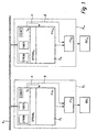
- the brake system comprises a wheel module R_1, R m for each vehicle wheel to be braked.
- Each wheel module R_1, R_m comprises a microcomputer system P_1, P_m and an enable circuit FS_1, FS_m.
- the microcomputer systems P_1, P_m each include a process computer Pro_1, Pro_m and an intelligent communication controller S_1, S_m.
- the process computer Pro_1, Pro_m and the communication controller S_1, S_m of a microcomputer system P_1, P_m can be combined on a semiconductor module (so-called chip); However, they are always designed as independent, separate units.
- Each wheel module R_1, R_m is connected via a communication controller S_1, S_m to a physical data bus K_1.
- the wheel modules R_1, R_m each control an actuator Akt_1, Akt_m, which, for example, comprises one or more electric motors for actuating or releasing the wheel brakes.
- the state of the art (cf. Fig. 2 ) known monitoring concept for checking the process computer (Pro_1) by a so-called.
- Question-answer communication is by the in Fig. 1 replaced inventive process computer communication controller concept replaced.
- the communication controller S-1 assumes the task of the monitoring unit R_1B from the prior art and periodically asks the process computer Pro_1 to receive the correct answer within a predefinable time window. In the event that the time window is not respected or the correct answer to the question does not arrive, the communication controller S_1 takes over the shutdown of the process computer Pro 1 (signal A) and / or the connected component Akt_1 via the enable circuit FS_1 (signal B).
- the communication controller S_1 merely has to be supplemented by a list of questions and answers.
- the communication protocol of the communication controller S_1 is supplemented with mechanisms that allow the periodic polling, the setting of the corresponding timers for the time window, the monitoring of this time window and the verification of the response.
- the communication controller S_1 has a pin (signal output A) for enabling the process computer Pro_1 and a pin (signal output B) for enabling the enable circuit FS_1. These pins are operated by the communication controller S_1.
- the communication controller S_1 executes a question-and-answer communication with the process computer Pro_1, which in the normal protocol sequence (actual transmission and reception of news, message confirmation, possibly membership service and global time). This results in a small overhead on the communications controller S_1, but a significant improvement in the use of existing devices within a distributed security-related system. Furthermore, the communication controller S_1 software and hardware interfaces available to allow the connection to the enable circuit FS_1 or to a suitable pin of the process computer Pro-1. The enable circuit FS_1 is thus operated on the one hand by the process computer Pro_1 and on the other hand by the communication controller S_. In addition, the process computer Pro_1 itself can be coupled to the communication controller S_1, so that the process computer Pro_1 itself can be turned off, for example by coupling to a reset line of the process computer Pro_1.
- the realization of the process-computer-communication controller concept according to the invention for carrying out the question-answer communication is possible with any control device which is equipped with a communication controller having a self-contained and independent clock. Ideally, this clock is even synchronized via a clock synchronization mechanism to a global time of the entire distributed safety-related system.
- the communication controller S_1 must implement the mechanism of the question-answer communication and have the necessary configuration data available or provide interfaces to the process computer Pro_1 and to the enable circuit FS_1.
- the communication controller S_1 must have the list of questions and the list of correct answers in its permanent Programmed memory.
- a Flash EPROM is particularly well-suited, on which usually also further configuration data for the actual communication are stored.
- the clock (timer) for setting the timeouts for the time window to be monitored must also be configured in advance.
- an error counter (Count) the upper limit must also be defined for it.
- the communication controller S_1 offers a hardware interface that allows a wiring of the resulting shutdown logic from the question-answer communication with the process computer Pro_1 (signal A) and with the additional enable circuit FS_1 (signal B).
- DPRAM_1 shared memory area (dual port RAM)
- This common memory area DPRAM_1 forms a software interface between the communication controller S_1 and the process computer Pro_1.
- a 16-bit value is set in the software interface by the communication controller S_1 (question) and the response is read out within the timeout from the software interface.
- another software interface can be available in the communication controller S_1 in order to make the status of the question-answer communication available to the outside (eg "timeout exceeded” or "answer OK").
- the communication controller S_1 must perform the evaluation of the response received from the process computer Pro_1 and a comparison with the responses stored in the response list. For this purpose, additional mechanisms are available in the normal communication protocol which allows addressing of the table in which the answer list is stored, and a simple comparison of two values. In addition, error counters may be managed.
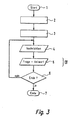
- the procedure begins in a function block 1.
- the starting situation is an active distributed network with functioning subscribers (communication controllers S_1, S_m and their process computers Pro_1, Pro_m). There is no signal for switching off the process computer Pro_1 or the component to be actuated Akt_1 (via the enable circuit FS_1).
- a system start is executed.
- an initialization of the communication controller S_1 and of the process computer Pro_1 is carried out.
- the normal application starts sending and receiving messages (function block 4).
- the communication controller S_1 also initiates the question-and-answer communication (function block 5).
- the two sequences shown only symbolically by the function blocks 4 and 5 are routines which can be executed not only one after the other but also side by side, ie simultaneously or quasi parallel.
- the question and answer routine 5 is in Fig. 4 shown in detail and is described in more detail below.
- a query block 6 is then checked whether the process should be terminated or not. The method is terminated, for example, when the corresponding subscriber or the entire distributed system is shut down. If the procedure should not be finished, will be again branches to the function block 4. Otherwise, the inventive method is terminated in a function block 7.
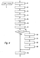
- a specific question is selected from the questionnaire stored in the memory element EPROM of the communication interface S_1.
- the selection of a question can be a cyclic execution of the questionnaire or a processing according to a predefinable pattern or a random procedure (eg coupled to the current system time of the communication controller S_1).
- the process computer Pro_1 is provided with the selected question via the software interface DPRAM_1 in a function block 52 and started in a function block 53 of the time counter (timer).
- the monitoring of the time window is part of the further protocol sequence in the communication controller S_1 and can also be solved differently, for. B. by so-called. Polling or by a so-called. Capture and Compare logic in the communication controller S_1.
- the process computer Pro_1 there is a suitable software which processes the question of the communication controller S_1 (function block 54) and determines a corresponding answer to the question (function block 55).
- the algorithms or methods used for this purpose are not the subject of this invention and can range from a simple inversion of the question to a complex calculation including a memory test.
- the software in the process computer Pro_1 then passes the answer in a function block 56 via the software interface DPRAM_1 to the communication controller S_1.
- a function block 57 the response is then read from the software interface DPRAM_1 in the communication controller S_1.
- a comparison of the response of the process computer Pro_1 with the correct answer entered in the answer list is carried out via an evaluation logic of the communication controller S_1.
- the communication controller S_1 receives the correct answer (output "no").
- the result of the question-answer communication is additionally set in a status register (function block 59); in this case a positive status.
- the question-and-answer routine 5 branches again to the function block 6 in FIG Fig. 3 ,
- the next question can then be sent to the process computer Pro_1, z. B. after the timeout, and the question-answer routine 5 is run again. This results in a cyclic question-answer protocol.
- the initiation of the next question can also be carried out at predetermined times (see also timed communication protocols that make each protocol step dependent on reaching a certain point in time).
- an error counter is first increased (function block 60). Subsequently, in a function block 61, the signal A is triggered to switch off the processor Pro_1. Likewise, in a function block 62, the signal B for switching off the actuators Akt_1 be sent via the enable circuit FS_1. Steps 61 and 62 can be executed at each error handling. Alternatively, however, they can also be processed only when the error counter, which has been increased in the function block 60, has exceeded a predefinable limit value. Through steps 61 and 62, the participation of the powered down units Pro_1, Act_1 on the communication is suspended until an ordered system reboot occurs. In a function block 63, the end of the method according to the invention is specified, so that the method is terminated in the next pass of the query block 6 in the function block 7.
Landscapes
- Physics & Mathematics (AREA)
- General Physics & Mathematics (AREA)
- Engineering & Computer Science (AREA)
- Automation & Control Theory (AREA)
- Safety Devices In Control Systems (AREA)
- Programmable Controllers (AREA)
- Regulating Braking Force (AREA)
Abstract
Claims (11)
- Procédé de commande d'un composant (Akt_1) d'un système distribué en rapport avec la sécurité, notamment un composant (Akt_1) d'un système tout électrique (X-by-wire) dans un véhicule automobile, le composant (Akt_1) étant commandé par un calculateur de processus (Pro_1) associé au composant (Akt_1), lequel est connecté à un système de communication (K_1) par le biais d'un contrôleur de communication (S_1), caractérisé en ce que le calculateur de processus (Pro_1) est surveillé par le contrôleur de communication (S_1) indépendamment du calculateur de processus (Pro_1).
- Procédé selon la revendication 1, caractérisé en ce que le contrôleur de communication (S_1) a à sa disposition une liste de questions qui sont posées au calculateur de processus (Pro_1) à surveiller à des instants à prédéfinir, le calculateur de processus (Pro_1) donnant au contrôleur de communication (S_1) une réponse qui est ensuite interprétée par celui-ci.
- Procédé selon la revendication 1, caractérisé en ce qu'il est vérifié si la réponse a eu lieu pendant une durée à prédéfinir.
- Procédé selon la revendication 2, caractérisé en ce qu'il est vérifié si la réponse est correcte.
- Procédé selon la revendication 4, caractérisé en ce qu'il est vérifié si la réponse est inscrite dans une liste en tant que réponse correcte à la question posée.
- Procédé selon l'une des revendications 2 à 5, caractérisé en ce que les questions sont posées périodiquement au calculateur de processus par le contrôleur de communication.
- Procédé selon l'une des revendications 1 à 6, caractérisé en ce que le contrôleur de communication prend en charge la mise hors circuit du calculateur de processus si la réponse est fausse et/ou n'a pas eu lieu pendant une durée à prédéfinir.
- Procédé selon l'une des revendications 1 à 6, caractérisé en ce que le contrôleur de communication prend en charge la mise hors circuit du composant à commander si la réponse est fausse et/ou n'a pas eu lieu pendant une durée à prédéfinir.
- Contrôleur de communication destiné à connecter un calculateur de processus (Pro_1) à un système de communication (K_1), le calculateur de processus servant à commander un composant d'un système distribué en rapport avec la sécurité, notamment un composant d'un système tout électrique (X-by-wire) dans un véhicule automobile, et un protocole de communication étant exécuté sur le contrôleur de communication (S_1) en vue de réaliser une transmission de données entre le calculateur de processus (Pro_1) et le système de communication (K_1), caractérisé en ce que le protocole de communication est complété par des mécanismes qui permettent au contrôleur de communication (S_1) de surveiller le calculateur de processus (Pro_1).
- Contrôleur de communication (S_1) selon la revendication 9, caractérisé en ce que le protocole de communication est complété par des mécanismes pour mettre en oeuvre un procédé selon l'une des revendications 2 à 8.
- Contrôleur de communication (S_1) selon la revendication 8 ou 9, caractérisé en ce que le contrôleur de communication présente un élément de mémoire, notamment une mémoire vive (RAM), une mémoire morte (ROM) ou une mémoire flash sur laquelle sont mémorisées les questions pour le calculateur de processus et les réponses correctes pour une communication question/réponse avec le calculateur de processus.
Applications Claiming Priority (3)
| Application Number | Priority Date | Filing Date | Title |
|---|---|---|---|
| DE10112914 | 2001-03-15 | ||
| DE10112914 | 2001-03-15 | ||
| PCT/DE2002/000914 WO2002075463A1 (fr) | 2001-03-15 | 2002-03-14 | Procede de commande d'un composant d'un systeme de securite distribue |
Publications (2)
| Publication Number | Publication Date |
|---|---|
| EP1384122A1 EP1384122A1 (fr) | 2004-01-28 |
| EP1384122B1 true EP1384122B1 (fr) | 2011-05-25 |
Family
ID=7677842
Family Applications (1)
| Application Number | Title | Priority Date | Filing Date |
|---|---|---|---|
| EP02722009A Expired - Lifetime EP1384122B1 (fr) | 2001-03-15 | 2002-03-14 | Procede de commande d'un composant d'un systeme de securite distribue |
Country Status (5)
| Country | Link |
|---|---|
| US (1) | US7269488B2 (fr) |
| EP (1) | EP1384122B1 (fr) |
| JP (1) | JP2004519059A (fr) |
| DE (1) | DE10291112D2 (fr) |
| WO (1) | WO2002075463A1 (fr) |
Families Citing this family (7)
| Publication number | Priority date | Publication date | Assignee | Title |
|---|---|---|---|---|
| JP2008542946A (ja) * | 2005-06-09 | 2008-11-27 | エヌエックスピー ビー ヴィ | 通信システムノード用記憶装置、データ記憶方法、及び通信システムノード |
| DE102005048581B4 (de) * | 2005-10-06 | 2022-06-09 | Robert Bosch Gmbh | Teilnehmerschnittstelle zwischen einem FlexRay-Kommunikationsbaustein und einem FlexRay-Teilnehmer und Verfahren zur Übertragung von Botschaften über eine solche Schnittstelle |
| WO2007044997A2 (fr) | 2005-10-13 | 2007-04-19 | Trw Automotive U.S. Llc | Procédé et appareil pour procurer une fonction de sécurité dans un système de retenue |
| JP2007307984A (ja) * | 2006-05-17 | 2007-11-29 | Toyota Motor Corp | 電気機器の配線接続構造および電動車両 |
| DE102007050708B4 (de) * | 2007-10-22 | 2009-08-06 | Phoenix Contact Gmbh & Co. Kg | System zum Betreiben wenigstens eines nicht-sicherheitskritischen und wenigstens eines sicherheitskritischen Prozesses |
| US9156357B2 (en) * | 2013-09-11 | 2015-10-13 | GM Global Technology Operations LLC | Controller for an electric motor, and a method thereof |
| CN107132835B (zh) * | 2017-04-14 | 2019-03-01 | 太原钢铁(集团)有限公司 | 一种异型控制系统通讯故障检测判断方法 |
Family Cites Families (13)
| Publication number | Priority date | Publication date | Assignee | Title |
|---|---|---|---|---|
| DE4438714A1 (de) * | 1994-10-29 | 1996-05-02 | Bosch Gmbh Robert | Verfahren und Vorrichtung zur Steuerung der Antriebseinheit eines Fahrzeugs |
| US5924774A (en) * | 1995-11-30 | 1999-07-20 | Zeftron, Inc. | Electronic pneumatic brake system |
| DE19716197A1 (de) | 1997-04-18 | 1998-10-22 | Itt Mfg Enterprises Inc | Mikroprozessorsystem für sicherheitskritische Regelungen |
| DE19717686A1 (de) | 1997-04-28 | 1998-10-29 | Itt Mfg Enterprises Inc | Schaltungsanordnung für ein Kraftfahrzeug-Regelungssystem |
| US6002970A (en) | 1997-10-15 | 1999-12-14 | International Business Machines Corp. | Method and apparatus for interface dual modular redundancy |
| DE19829126A1 (de) | 1997-11-22 | 1999-05-27 | Itt Mfg Enterprises Inc | Elektromechanisches Bremssystem |
| DE19826131A1 (de) * | 1998-06-12 | 1999-12-16 | Bosch Gmbh Robert | Elektrisches Bremssystem für ein Kraftfahrzeug |
| GB2339869B (en) | 1998-07-20 | 2002-05-15 | Motorola Ltd | Fault-tolerant electronic braking system |
| DE19840484A1 (de) * | 1998-09-04 | 2000-03-09 | Bosch Gmbh Robert | Fahrzeugrechneranordnung |
| GB2345161A (en) * | 1998-12-23 | 2000-06-28 | Motorola Ltd | Microprocessor module and method |
| DE19933086B4 (de) | 1999-07-15 | 2008-11-20 | Robert Bosch Gmbh | Verfahren und Vorrichtung zur gegenseitigen Überwachung von Steuereinheiten |
| DE19937159B4 (de) * | 1999-08-06 | 2019-03-21 | Robert Bosch Gmbh | Elektrisch gesteuertes Bremssystem |
| DE19939567B4 (de) | 1999-08-20 | 2007-07-19 | Pilz Gmbh & Co. Kg | Vorrichtung zum Steuern von sicherheitskritischen Prozessen |
-
2002
- 2002-03-14 DE DE10291112T patent/DE10291112D2/de not_active Expired - Lifetime
- 2002-03-14 WO PCT/DE2002/000914 patent/WO2002075463A1/fr not_active Ceased
- 2002-03-14 US US10/276,603 patent/US7269488B2/en not_active Expired - Fee Related
- 2002-03-14 JP JP2002574008A patent/JP2004519059A/ja active Pending
- 2002-03-14 EP EP02722009A patent/EP1384122B1/fr not_active Expired - Lifetime
Also Published As
| Publication number | Publication date |
|---|---|
| EP1384122A1 (fr) | 2004-01-28 |
| US20040030482A1 (en) | 2004-02-12 |
| US7269488B2 (en) | 2007-09-11 |
| WO2002075463A1 (fr) | 2002-09-26 |
| DE10291112D2 (de) | 2004-04-15 |
| JP2004519059A (ja) | 2004-06-24 |
Similar Documents
| Publication | Publication Date | Title |
|---|---|---|
| DE10223880B4 (de) | Verfahren zur gegenseitigen Überwachung von Komponenten eines dezentral verteilten Rechnersystems | |
| DE3811217C2 (fr) | ||
| DE102017209721B4 (de) | Vorrichtung für die Steuerung eines sicherheitsrelevanten Vorganges, Verfahren zum Testen der Funktionsfähigkeit der Vorrichtung, sowie Kraftfahrzeug mit der Vorrichtung | |
| EP2550599B1 (fr) | Système d'ordinateur de commande, procédé de commande d'un système d'ordinateur de commande, et utilisation d'un système d'ordinateur de commande | |
| DE102008063625B4 (de) | Fahrzeug-Elektroniksteuervorrichtung mit einem Überwachungssteuerschaltkreis | |
| AT515454A2 (de) | Verfahren zur Behandlung von Fehlern in einem zentralen Steuergerät sowie Steuergerät | |
| DE102014102582A1 (de) | Fehlertolerantes Steuerungssystem | |
| EP1653363A1 (fr) | Noeud dans un réseau de bus, réseau de bus et procédé de la configuration d'un réseau | |
| WO2007074058A1 (fr) | Unite de surveillance de bus d'un abonne de systeme de communication, et abonne pour un systeme de communication | |
| DE102019200994A1 (de) | Ein datenkommunikationsverfahren für ein fahrzeug | |
| DE10211278A1 (de) | Verfahren zur Ansteuerung einer Komponente eines verteilten sicherheitsrelevanten Systems | |
| EP1053153B1 (fr) | Procede pour le traitement d'erreurs dans un systeme de freinage electronique et dispositif associe | |
| EP2491492B1 (fr) | Système d'automatisation et procédé pour faire fonctionner un système d'automatisation | |
| EP2040965A1 (fr) | Procédé pour synchroniser des composants d'un système de frein d'un véhicule automobile et système de commande de frein électronique | |
| EP1384122B1 (fr) | Procede de commande d'un composant d'un systeme de securite distribue | |
| EP3298730B1 (fr) | Système de bus et procédé d'attribution d'adresses à des abonnés d'un système de bus | |
| WO2014033171A1 (fr) | Procédé de surveillance d'un dispositif relié à un canal de communication | |
| DE19842593C2 (de) | Verfahren zum Betrieb eines Busmasters an einem Feldbus | |
| DE10211279A1 (de) | Verfahren zum Betreiben eines verteilten sicherheitsrelevanten Systems | |
| EP3573290B1 (fr) | Procédé de fonctionnement d'un dispositif capteur dans un véhicule automobile à base d'un protocole dsi | |
| DE60309012T2 (de) | Verfahren und system zur sicherstellung eines busses und eines steuerservers | |
| DE3928537A1 (de) | Verfahren zur fehlererkennung und/oder fehlerlokalisation bei datenuebertragungen | |
| EP2359254B1 (fr) | Procédé et système de commande de la communication entre un calculateur fonctionnel et un module de surveillance | |
| DE10211280A1 (de) | Verfahren zur Ansteuerung einer Komponente eines verteilten sicherheitsrelevanten Systems | |
| DE112016006679T5 (de) | Steuerungsvorrichtung und Recovery-Verarbeitungsverfahren für Steuerungsvorrichtung |
Legal Events
| Date | Code | Title | Description |
|---|---|---|---|
| PUAI | Public reference made under article 153(3) epc to a published international application that has entered the european phase |
Free format text: ORIGINAL CODE: 0009012 |
|
| 17P | Request for examination filed |
Effective date: 20031015 |
|
| AK | Designated contracting states |
Kind code of ref document: A1 Designated state(s): AT BE CH CY DE DK ES FI FR GB GR IE IT LI LU MC NL PT SE TR |
|
| AX | Request for extension of the european patent |
Extension state: AL LT LV MK RO SI |
|
| RIN1 | Information on inventor provided before grant (corrected) |
Inventor name: MUELLER, BERND Inventor name: FUEHRER, THOMAS |
|
| 17Q | First examination report despatched |
Effective date: 20060403 |
|
| GRAP | Despatch of communication of intention to grant a patent |
Free format text: ORIGINAL CODE: EPIDOSNIGR1 |
|
| RIN1 | Information on inventor provided before grant (corrected) |
Inventor name: MUELLER, BERND Inventor name: FUEHRER, THOMAS |
|
| GRAS | Grant fee paid |
Free format text: ORIGINAL CODE: EPIDOSNIGR3 |
|
| GRAA | (expected) grant |
Free format text: ORIGINAL CODE: 0009210 |
|
| AK | Designated contracting states |
Kind code of ref document: B1 Designated state(s): DE FR GB |
|
| REG | Reference to a national code |
Ref country code: GB Ref legal event code: FG4D Free format text: NOT ENGLISH |
|
| REG | Reference to a national code |
Ref country code: DE Ref legal event code: R096 Ref document number: 50215062 Country of ref document: DE Effective date: 20110707 |
|
| PLBE | No opposition filed within time limit |
Free format text: ORIGINAL CODE: 0009261 |
|
| STAA | Information on the status of an ep patent application or granted ep patent |
Free format text: STATUS: NO OPPOSITION FILED WITHIN TIME LIMIT |
|
| 26N | No opposition filed |
Effective date: 20120228 |
|
| REG | Reference to a national code |
Ref country code: DE Ref legal event code: R097 Ref document number: 50215062 Country of ref document: DE Effective date: 20120228 |
|
| PGFP | Annual fee paid to national office [announced via postgrant information from national office to epo] |
Ref country code: FR Payment date: 20130329 Year of fee payment: 12 Ref country code: GB Payment date: 20130318 Year of fee payment: 12 |
|
| REG | Reference to a national code |
Ref country code: DE Ref legal event code: R084 Ref document number: 50215062 Country of ref document: DE Effective date: 20130422 |
|
| PGFP | Annual fee paid to national office [announced via postgrant information from national office to epo] |
Ref country code: DE Payment date: 20140523 Year of fee payment: 13 |
|
| GBPC | Gb: european patent ceased through non-payment of renewal fee |
Effective date: 20140314 |
|
| REG | Reference to a national code |
Ref country code: FR Ref legal event code: ST Effective date: 20141128 |
|
| PG25 | Lapsed in a contracting state [announced via postgrant information from national office to epo] |
Ref country code: GB Free format text: LAPSE BECAUSE OF NON-PAYMENT OF DUE FEES Effective date: 20140314 Ref country code: FR Free format text: LAPSE BECAUSE OF NON-PAYMENT OF DUE FEES Effective date: 20140331 |
|
| REG | Reference to a national code |
Ref country code: DE Ref legal event code: R119 Ref document number: 50215062 Country of ref document: DE |
|
| PG25 | Lapsed in a contracting state [announced via postgrant information from national office to epo] |
Ref country code: DE Free format text: LAPSE BECAUSE OF NON-PAYMENT OF DUE FEES Effective date: 20151001 |