EP1384448A1 - Vorrichtung zur galvanischen Abscheidung prothetischer, metallischer Dentalformteile - Google Patents
Vorrichtung zur galvanischen Abscheidung prothetischer, metallischer Dentalformteile Download PDFInfo
- Publication number
- EP1384448A1 EP1384448A1 EP03014162A EP03014162A EP1384448A1 EP 1384448 A1 EP1384448 A1 EP 1384448A1 EP 03014162 A EP03014162 A EP 03014162A EP 03014162 A EP03014162 A EP 03014162A EP 1384448 A1 EP1384448 A1 EP 1384448A1
- Authority
- EP
- European Patent Office
- Prior art keywords
- beaker
- infrared radiator
- electrolyte bath
- bath
- electrolyte
- Prior art date
- Legal status (The legal status is an assumption and is not a legal conclusion. Google has not performed a legal analysis and makes no representation as to the accuracy of the status listed.)
- Granted
Links
Images



Classifications
-
- C—CHEMISTRY; METALLURGY
- C25—ELECTROLYTIC OR ELECTROPHORETIC PROCESSES; APPARATUS THEREFOR
- C25D—PROCESSES FOR THE ELECTROLYTIC OR ELECTROPHORETIC PRODUCTION OF COATINGS; ELECTROFORMING; APPARATUS THEREFOR
- C25D17/00—Constructional parts, or assemblies thereof, of cells for electrolytic coating
-
- A—HUMAN NECESSITIES
- A61—MEDICAL OR VETERINARY SCIENCE; HYGIENE
- A61C—DENTISTRY; APPARATUS OR METHODS FOR ORAL OR DENTAL HYGIENE
- A61C13/00—Dental prostheses; Making same
- A61C13/0003—Making bridge-work, inlays, implants or the like
-
- C—CHEMISTRY; METALLURGY
- C25—ELECTROLYTIC OR ELECTROPHORETIC PROCESSES; APPARATUS THEREFOR
- C25D—PROCESSES FOR THE ELECTROLYTIC OR ELECTROPHORETIC PRODUCTION OF COATINGS; ELECTROFORMING; APPARATUS THEREFOR
- C25D21/00—Processes for servicing or operating cells for electrolytic coating
- C25D21/02—Heating or cooling
-
- C—CHEMISTRY; METALLURGY
- C25—ELECTROLYTIC OR ELECTROPHORETIC PROCESSES; APPARATUS THEREFOR
- C25D—PROCESSES FOR THE ELECTROLYTIC OR ELECTROPHORETIC PRODUCTION OF COATINGS; ELECTROFORMING; APPARATUS THEREFOR
- C25D21/00—Processes for servicing or operating cells for electrolytic coating
- C25D21/10—Agitating of electrolytes; Moving of racks
Definitions
- the invention relates to a device for the galvanic deposition of prosthetic, metallic Dental molded parts, with a beaker for holding an electrolyte bath, a stirring system for moving the electrolyte bath, a heating system for heating the electrolyte bath, at least one anode and at least one cathode and an electrical supply unit, which is connected to the at least one anode and the at least one cathode.
- the invention further relates to the use of this device and a method for the production prosthetic, metallic dental molded parts by galvanic deposition from one Electrolyte bath, the electrolyte bath being heated and moved.
- Such a device or such a method is known from DE 198 45 506 A1.
- the process which is also referred to as the electroforming process, describes the Manufacture of prosthetic molded parts for the dental sector with the help of galvanic deposition of metal, especially precious metals and precious metal alloys.
- the prosthetic manufactured Shaped parts are, for example, dental frameworks on which ceramic or plastic is used Facing can be applied. Molded parts can also be produced that are and bridge technology are used or also those that have a direct use Find.
- an electrolyte bath for the galvanic deposition of the noble metal is particularly important here discloses an aqueous gold sulfite bath.
- the equipment used to carry out the process consists of a heated magnetic stirrer for moving the electrolyte bath, a Temperature sensor for measuring the temperature of the electrolyte bath, a current-voltage source, an electrolytic cell consisting of a beaker with cover and a Stirring rod as well as the anodes, the cathodes and the electrolyte bath.
- the electrolytic bath is at deposition temperatures greater than 30 ° C, preferably heated to a temperature in the range of 50 to 80 ° C.
- DE 38 09 435 A1 discloses a device and a method for producing an inner one Precious metal crown for galvanic deposition.
- the device exposes itself a bath tank with the galvanic bath, a propeller stirrer for moving the bath, a resistance heating coil for heating the bath, an anode, a cathode, one Auxiliary electrode and a power source together.
- JP 52-089536 discloses the irradiation of an electrolyte with radiation of the wavelength 200 to 450 nm (UV radiation).
- the electrolyte is a tin bath, in which metallic tin particles should be loosened.
- the UV radiation causes removal the oxide skin on the individual metallic tin particles and thus improves the dissolving behavior this one in the tin bath.
- the device used has a glass container in which the tin bath and the metallic tin powder are located. It will Tin bath moved by a magnetic stirrer.
- the UV lamp for irradiating the suspension is located above the surface of the suspension.
- US 4,246,086 discloses the production of metallic or ceramic layers by electrophoretic or galvanic deposition to form dental crowns or dental bridges.
- An apparatus is disclosed which has a glass or plastic container with a Has electrophoresis bath or a galvanic bath. The bathroom is done by one Magnetic stirrer moves.
- a heating system which is formed from at least one infrared radiator, the main part of the emission of which lies in a wavelength range from 0.5 ⁇ m to 1000 ⁇ m. Heating the electrolyte bath by heat radiation is significantly faster than heating by heat conduction. By using thermal radiation, shorter heating times can be achieved by a factor of 3 to 5. This is particularly important if the deposition times for a dental molded part are relatively short.
- the at least one infrared radiator next to the Beaker or arranged parallel to the wall of the beaker Farther it is possible to place the at least one infrared emitter above the beaker or above the Arrange beaker. However, it must be ensured that the attachment the anode (s) and cathode (s) in the beaker allow the radiation to enter the electrolyte.
- the at least one infrared radiator can be integrated in this cover or be arranged above the lid if it is transparent to the heat radiation is.
- the infrared heater can be combined with a magnetic stirrer, so that a stirring movement in the electrolyte bath is possible.
- the at least one infrared radiator in the beaker or to integrate in a wall of the beaker.
- the infrared heater can also be used entirely or partially immerse in the electrolyte bath.
- the at least one infrared radiator surrounds the maximum diameter of the beaker.
- the beaker can For example, be placed in the middle of a helical infrared radiator.
- one annular arrangement of infrared radiators with a tubular cross section, which are parallel or are aligned tangentially to the cup wall is conceivable.
- the main part of the emission of the at least one infrared radiator is in a wavelength range from 0.5 ⁇ m to 4 ⁇ m.
- Quartz glass for example, has proven itself as a beaker material. Here, however, is heading for it make sure that quartz glass is usually not transparent for wavelengths greater than 4 ⁇ m and this is taken into account when selecting the infrared radiator and / or its arrangement must become.
- the at least an infrared radiator is suitable for generating polychromatic radiation. Indeed it is also possible to use an infrared radiator, which is used to generate a monochromatic Radiation is suitable.
- thermocontrol of the electrolyte bath it has also proven itself to be a temperature sensor provided. It has proven useful to arrange the temperature sensor in the electrolyte bath.
- the anode (s) and the cathode (s) are attached to a cover which is used for Sealing the beaker is suitable. This is a quick and easy placement of the objects to be coated possible in the electrolyte bath.
- the problem is solved for the method in that the electrolyte bath is heated with at least one infrared radiator, the main part of the emission of which is in a wavelength range from 0.5 ⁇ m to 1000 ⁇ m. Heating the electrolyte bath by heat radiation is significantly faster than heating by heat conduction. By using thermal radiation, shorter heating times can be achieved by a factor of 3 to 5. This is particularly important if the deposition times for a dental molded part are relatively short.
- the main part of the emission is in a wavelength range from 0.5 ⁇ m to 4 ⁇ m.
- the at least one infrared emitter is a polychromatic Emits radiation.
- an infrared radiator can also be used, the monochromatic one Emits radiation.
- a noble metal bath is preferably used as the electrolyte bath.
- aqueous gold baths for use. But also baths for the deposition of precious metal alloys are preferred.
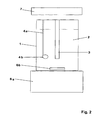
- Fig. 1 shows the schematic structure of a known device for performing the electroforming process with a beaker 1, which is filled with an electrolyte bath 2. in the electrolyte bath 2 there is an anode 3 and a cathode 4a, on which a molded part 4b is arranged, on the Surface of the metal to be deposited from the electrolyte bath 2.
- the beaker 1 is located to heat the electrolyte bath 2 on a resistance-heated heating plate 5.
- a magnetic stirrer 6a is provided, via which a magnetic stirring rod 6b is moved in the electrolyte bath 2 and causes an intensive movement of the electrolyte bath 2.
- the electrical contacting of the anode 3 and the cathode 4a, 4b is not shown separately.
- Fig. 2 shows an example of the schematic structure of a device according to the invention, in which an infrared radiator 7 is arranged above the beaker 1.
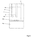
- Fig. 3 shows an example of the schematic structure of a device according to the invention, in which an infrared radiator 7 is arranged below the beaker 1.
- Fig. 4 shows an example of the schematic structure of a device according to the invention, in which an infrared radiator 7 is arranged next to the beaker 1.
- Fig. 5 shows an example of the schematic structure of a device according to the invention, in which an infrared radiator 7 is immersed in the electrolyte bath 2.
Landscapes
- Chemical & Material Sciences (AREA)
- Health & Medical Sciences (AREA)
- Organic Chemistry (AREA)
- Engineering & Computer Science (AREA)
- Metallurgy (AREA)
- Materials Engineering (AREA)
- Electrochemistry (AREA)
- Chemical Kinetics & Catalysis (AREA)
- Public Health (AREA)
- Dentistry (AREA)
- Veterinary Medicine (AREA)
- Epidemiology (AREA)
- General Health & Medical Sciences (AREA)
- Animal Behavior & Ethology (AREA)
- Life Sciences & Earth Sciences (AREA)
- Oral & Maxillofacial Surgery (AREA)
- Radiation-Therapy Devices (AREA)
- Dental Prosthetics (AREA)
- Dental Preparations (AREA)
- Electroplating Methods And Accessories (AREA)
Abstract
Description
Eine Erwärmung des Elektrolytbades durch Wärmestrahlung ist signifikant schneller als eine Erwärmung durch Wärmeleitung. Dabei können durch Verwendung von Wärmestrahlung um den Faktor 3 bis 5 kürzere Erwärmungszeiten erreicht werden. Dies ist insbesondere dann wichtig, wenn die Abscheidezeiten für ein Dentalformteil verhältnismäßig kurz sind.
Eine Erwärmung des Elektrolytbades durch Wärmestrahlung ist signifikant schneller als eine Erwärmung durch Wärmeleitung. Dabei können durch Verwendung von Wärmestrahlung um den Faktor 3 bis 5 kürzere Erwärmungszeiten erreicht werden. Dies ist insbesondere dann wichtig, wenn die Abscheidezeiten für ein Dentalformteil verhältnismäßig kurz sind.
- Fig. 1
- den schematischen Aufbau einer bekannten Vorrichtung zur Durchführung des Galvanoforming-Verfahrens
- Fig. 2
- den schematischen Aufbau einer erfindungsgemäßen Vorrichtung, bei welcher der Infrarotstrahler oberhalb des Becherglases angeordnet ist,
- Fig. 3
- den schematischen Aufbau einer erfindungsgemäßen Vorrichtung, bei welcher der Infrarotstrahler unterhalb des Becherglases angeordnet ist,
- Fig. 4
- den schematischen Aufbau einer erfindungsgemäßen Vorrichtung, bei welcher der Infrarotstrahler neben dem Becherglas angeordnet ist, und
- Fig. 5
- den schematischen Aufbau einer erfindungsgemäßen Vorrichtung, bei welcher der Infrarotstrahler in das Elektrolytbad eingetaucht ist.
Claims (16)
- Vorrichtung zur galvanischen Abscheidung prothetischer, metallischer Dentalformteile, mit:das Heizsystem aus mindestens einem Infrarotstrahler gebildet ist, dessen Hauptanteil der Emission in einem Wellenlängenbereich von 0,5 µm bis 1000 µm liegt.einem Becherglas zur Aufnahme eines Elektrolytbades,einem Rührsystem zur Bewegung des Elektrolytbades,einem Heizsystem zur Beheizung des Elektrolytbades,mindestens einer Anode und mindestens einer Kathode, undeiner elektrischen Versorgungseinheit, die mit der mindestens einen Anode und der mindestens einen Kathode verbunden ist, dadurch gekennzeichnet, dass
- Vorrichtung nach Anspruch 1, dadurch gekennzeichnet, dass der mindestens eine Infrarotstrahlera) neben dem Becherglas und/oderb) oberhalb des Becherglases und/oderc) unterhalb des Becherglases und/oderd) in dem Becherglas und/odere) den maximalen Durchmesser des Becherglases umgebend angeordnet ist und dass mindestens bei Auftreten von einem der Fälle a) oder c) oder e) das Becherglas aus einem Material gebildet ist, das zumindest für den Hauptanteil der Emission des mindestens einen Infrarotstrahlers durchlässig ist.
- Vorrichtung nach einem der Ansprüche 1 bis 2, dadurch gekennzeichnet, dass der Hauptanteil der Emission des mindestens einen Infrarotstrahlers in einem Wellenlängenbereich von 0,5 µm bis 4 µm liegt.
- Vorrichtung nach einem der Ansprüche 1 bis 3, dadurch gekennzeichnet, dass das Becherglas aus Quarzglas gebildet ist.
- Vorrichtung nach einem der Ansprüche 1 bis 4, dadurch gekennzeichnet, dass der mindestens eine Infrarotstrahler zur Erzeugung einer polychromatischen Strahlung geeignet ist.
- Vorrichtung nach einem der Ansprüche 1 bis 4, dadurch gekennzeichnet, dass der mindestens eine Infrarotstrahler zur Erzeugung einer monochromatischen Strahlung geeignet ist.
- Vorrichtung nach einem der Ansprüche 1 bis 6, dadurch gekennzeichnet, dass das Rührsystem ein Magnetrührsystem ist.
- Vorrichtung nach einem der Ansprüche 1 bis 7, dadurch gekennzeichnet, dass ein Temperaturfühler zum Messen der Temperatur des Elektrolytbades vorhanden ist.
- Vorrichtung nach einem der Ansprüche 1 bis 8, dadurch gekennzeichnet, dass die Anode(n) und die Kathode(n) an einem Deckel befestigt sind, der zum Verschließen des Becherglases geeignet ist.
- Verwendung einer Vorrichtung nach einem der Ansprüche 1 bis 9 zur galvanischen Abscheidung dreidimensionaler prothetischer metallischer Dentalformteile.
- Verfahren zur Herstellung prothetischer, metallischer Dentalformteile durch galvanische Abscheidung aus einem Elektrolytbad, wobei das Elektrolytbad beheizt und bewegt wird, dadurch gekennzeichnet, dass das Elektrolytbad mit mindestens einem Infrarotstrahler beheizt wird, dessen Hauptanteil der Emission in einem Wellenlängenbereich von 0,5 µm bis 1000 µm liegt.
- Verfahren nach Anspruch 11, dadurch gekennzeichnet, das Elektrolytbad mit mindestens einem Infrarotstrahler beheizt wird, dessen Hauptanteil der Emission in einem Wellenlängenbereich von 0,5 µm bis 4 µm liegt.
- Verfahren nach einem der Ansprüche 11 bis 12, dadurch gekennzeichnet, dass der Infrarotstrahler eine polychromatische Strahlung aussendet.
- Verfahren nach einem der Ansprüche 11 bis 12, dadurch gekennzeichnet, dass der Infrarotstrahler eine monochromatische Strahlung aussendet.
- Verfahren nach einem der Ansprüche 11 bis 14, dadurch gekennzeichnet, dass als Elektrolytbad ein Edelmetallbad verwendet wird.
- Verfahren nach Anspruch 15, dadurch gekennzeichnet, dass als Edelmetallbad ein Goldbad verwendet wird.
Applications Claiming Priority (2)
| Application Number | Priority Date | Filing Date | Title |
|---|---|---|---|
| DE10234285 | 2002-07-26 | ||
| DE10234285A DE10234285B4 (de) | 2002-07-26 | 2002-07-26 | Vorrichtung zur galvanischen Abscheidung prothetischer, metallischer Dentalformteile |
Publications (2)
| Publication Number | Publication Date |
|---|---|
| EP1384448A1 true EP1384448A1 (de) | 2004-01-28 |
| EP1384448B1 EP1384448B1 (de) | 2006-08-02 |
Family
ID=29796596
Family Applications (1)
| Application Number | Title | Priority Date | Filing Date |
|---|---|---|---|
| EP03014162A Expired - Lifetime EP1384448B1 (de) | 2002-07-26 | 2003-06-24 | Vorrichtung zur galvanischen Abscheidung prothetischer, metallischer Dentalformteile |
Country Status (6)
| Country | Link |
|---|---|
| US (1) | US20040108199A1 (de) |
| EP (1) | EP1384448B1 (de) |
| JP (1) | JP2004089702A (de) |
| AT (1) | ATE334636T1 (de) |
| DE (2) | DE10234285B4 (de) |
| DK (1) | DK1384448T3 (de) |
Cited By (1)
| Publication number | Priority date | Publication date | Assignee | Title |
|---|---|---|---|---|
| EP1930482A2 (de) | 2006-11-07 | 2008-06-11 | BEGO Bremer Goldschlägerei Wilh. Herbst GmbH & Co. KG | Beheiztes Elektropoliergerät |
Families Citing this family (2)
| Publication number | Priority date | Publication date | Assignee | Title |
|---|---|---|---|---|
| DE102008006166A1 (de) * | 2008-01-26 | 2009-07-30 | Schott Solar Gmbh | Verfahren zur Herstellung eines photovoltaischen Moduls |
| JP2011058015A (ja) * | 2009-09-07 | 2011-03-24 | Toyo Tanso Kk | 電解装置 |
Citations (5)
| Publication number | Priority date | Publication date | Assignee | Title |
|---|---|---|---|---|
| JPS5289536A (en) * | 1976-01-23 | 1977-07-27 | Nippon Steel Corp | Method of melting at high speed tin to be poured in tin plating bath |
| DE3809435A1 (de) * | 1987-04-10 | 1988-10-20 | G C Dental Ind Corp | Verfahren und vorrichtung zur herstellung einer inneren krone einer aus schichten zusammengesetzten krone zur wiederherstellung von kronen |
| DE8911651U1 (de) * | 1989-09-29 | 1989-12-14 | Hornig, Wolfgang, Dr., 6902 Sandhausen | Galvanisiergerät zur Herstellung galvanisch beschichteter metallischer Teile, insbesondere Zahnersatzteile |
| WO1992007977A1 (de) * | 1990-10-29 | 1992-05-14 | Gerhard Gramm | Vorrichtung zum auftragen von überzügen bei werkstücken im dentalen bereich |
| EP0990423A1 (de) * | 1998-10-02 | 2000-04-05 | Wieland Edelmetalle GmbH & Co. | Verfahren zur Herstellung von prothetischen Formteilen für den Dentalbereich und prothetisches Formteil |
Family Cites Families (8)
| Publication number | Priority date | Publication date | Assignee | Title |
|---|---|---|---|---|
| DE1835092U (de) * | 1960-07-25 | 1961-07-20 | Dreve Dentamid | Vorrichtung zum herstellen von zahnprothesen. |
| US3307972A (en) * | 1963-03-11 | 1967-03-07 | Bell Telephone Labor Inc | Electroless copper deposition |
| DE2705770B2 (de) * | 1977-02-11 | 1980-03-06 | Bego Bremer Goldschlaegerei Wilh. Herbst, 2800 Bremen | Verfahren und Vorrichtung zum Aufbringen einer Grundmasse-Schicht auf einen metallischen Grundformling in der Dentaltechnik |
| US4217185A (en) * | 1979-07-02 | 1980-08-12 | The Dow Chemical Company | Electrolytic production of certain trichloropicolinic acids and/or 3,6-dichloropicolinic acid |
| DE2933269C2 (de) * | 1979-08-16 | 1982-08-12 | Siemens Ag, 1000 Berlin Und 8000 Muenchen | Vorrichtung zur Durchführung von Wärmearbeiten in der zahnärztlichen Praxis |
| US4251327A (en) * | 1980-01-14 | 1981-02-17 | Motorola, Inc. | Electroplating method |
| US6248225B1 (en) * | 1998-05-26 | 2001-06-19 | Ppg Industries Ohio, Inc. | Process for forming a two-coat electrodeposited composite coating the composite coating and chip resistant electrodeposited coating composition |
| JP2001355074A (ja) * | 2000-04-10 | 2001-12-25 | Sony Corp | 無電解メッキ処理方法およびその装置 |
-
2002
- 2002-07-26 DE DE10234285A patent/DE10234285B4/de not_active Expired - Fee Related
-
2003
- 2003-06-24 EP EP03014162A patent/EP1384448B1/de not_active Expired - Lifetime
- 2003-06-24 AT AT03014162T patent/ATE334636T1/de active
- 2003-06-24 DE DE50304433T patent/DE50304433D1/de not_active Expired - Lifetime
- 2003-06-24 DK DK03014162T patent/DK1384448T3/da active
- 2003-07-24 JP JP2003201313A patent/JP2004089702A/ja active Pending
- 2003-07-28 US US10/628,828 patent/US20040108199A1/en not_active Abandoned
Patent Citations (5)
| Publication number | Priority date | Publication date | Assignee | Title |
|---|---|---|---|---|
| JPS5289536A (en) * | 1976-01-23 | 1977-07-27 | Nippon Steel Corp | Method of melting at high speed tin to be poured in tin plating bath |
| DE3809435A1 (de) * | 1987-04-10 | 1988-10-20 | G C Dental Ind Corp | Verfahren und vorrichtung zur herstellung einer inneren krone einer aus schichten zusammengesetzten krone zur wiederherstellung von kronen |
| DE8911651U1 (de) * | 1989-09-29 | 1989-12-14 | Hornig, Wolfgang, Dr., 6902 Sandhausen | Galvanisiergerät zur Herstellung galvanisch beschichteter metallischer Teile, insbesondere Zahnersatzteile |
| WO1992007977A1 (de) * | 1990-10-29 | 1992-05-14 | Gerhard Gramm | Vorrichtung zum auftragen von überzügen bei werkstücken im dentalen bereich |
| EP0990423A1 (de) * | 1998-10-02 | 2000-04-05 | Wieland Edelmetalle GmbH & Co. | Verfahren zur Herstellung von prothetischen Formteilen für den Dentalbereich und prothetisches Formteil |
Cited By (1)
| Publication number | Priority date | Publication date | Assignee | Title |
|---|---|---|---|---|
| EP1930482A2 (de) | 2006-11-07 | 2008-06-11 | BEGO Bremer Goldschlägerei Wilh. Herbst GmbH & Co. KG | Beheiztes Elektropoliergerät |
Also Published As
| Publication number | Publication date |
|---|---|
| DK1384448T3 (da) | 2006-11-27 |
| DE10234285A1 (de) | 2004-02-12 |
| ATE334636T1 (de) | 2006-08-15 |
| US20040108199A1 (en) | 2004-06-10 |
| JP2004089702A (ja) | 2004-03-25 |
| DE10234285B4 (de) | 2006-12-07 |
| EP1384448B1 (de) | 2006-08-02 |
| DE50304433D1 (de) | 2006-09-14 |
Similar Documents
| Publication | Publication Date | Title |
|---|---|---|
| DE60225352T2 (de) | Verfahren zum elektroplattieren von metallischen und metallmatrix-komposite folien, beschichtungen und mikrokomponenten | |
| DE2705770A1 (de) | Verfahren und vorrichtung zum beschichten von kronen, bruecken etc. in der dentaltechnik | |
| DE102010016973A1 (de) | Verfahren zur Herstellung eines einseitig metallisierten Bedienelements aus Kunststoff mit hinterleuchtbarer Symbolik | |
| EP0990423B1 (de) | Verfahren zur Herstellung von prothetischen Formteilen für den Dentalbereich und prothetisches Formteil | |
| DE102016208184A1 (de) | Verfahren zum Erzeugen mehrerer elektrischer Strompfade auf einem Werkstück | |
| DE102015004150A1 (de) | Verfahren zur Herstellung eines Kontaktabstandswandlers sowie Kontaktabstandswandler | |
| DE2729488A1 (de) | Herstellungsverfahren fuer kuenstliche zaehne oder zahnteile | |
| DE10228323B4 (de) | Verfahren zum kathodischen elektrolytischen Abscheiden und Mikrokomponenten, hergestellt durch ein solches Verfahren | |
| DE3809435C2 (de) | Verfahren und Vorrichtung zur Herstellung einer inneren Krone einer aus Schichten zusammengesetzten Krone zur Wiederherstellung von Kronen | |
| EP0236782B1 (de) | Verfahren zur Herstellung von metallischen Zahnersatzteilen | |
| EP1384448B1 (de) | Vorrichtung zur galvanischen Abscheidung prothetischer, metallischer Dentalformteile | |
| EP0986818A1 (de) | Medizinische radioaktive ruthenium-strahlenquellen hoher dosisleistung und verfahren zur herstellung dieser | |
| DE3919792C2 (de) | ||
| EP0094615B1 (de) | Verfahren zum Herstellen von Zahnersatzteilen aus Metall | |
| DE4442792A1 (de) | Verfahren zur Herstellung einer korrosions- und verschleißschützenden Oxidschicht mit örtlich reduzierter Schichtdicke auf der Metalloberfläche eines Werkstücks | |
| DE102016208185A1 (de) | Werkstück mit elektrischen Strompfaden | |
| Kuhn et al. | The electroforming of gold and its alloys | |
| DE10262102B4 (de) | Verfahren zum kathodischen elektrolytischen Abscheiden | |
| DE3840399A1 (de) | Verfahren zur herstellung von metallischen zahnersatzteilen | |
| DE2510187A1 (de) | Verfahren zur herstellung von bei hohen temperaturen korrosionsbestaendigen koerpern aus einer kobalt-chrom-kohlenstofflegierung | |
| DE3307039C2 (de) | Werkstück aus Palladium mit einer mittels Schmelzflußelektrolyse aufgebrachten Schicht | |
| WO2004085714A1 (de) | Vorrichtung und deren teile für die galvanische abscheidung von dentalen formteilen | |
| DE1095614B (de) | Verfahren zum Herstellen eines Metallgegenstandes, insbesondere eines Wellenleiters, auf galvanoplastischem Wege | |
| DE102006018076B4 (de) | Verfahren zur Herstellung von Formteilen für den Dentalbereich | |
| DD202456A5 (de) | Verfahren zum schmelzen |
Legal Events
| Date | Code | Title | Description |
|---|---|---|---|
| PUAI | Public reference made under article 153(3) epc to a published international application that has entered the european phase |
Free format text: ORIGINAL CODE: 0009012 |
|
| 17P | Request for examination filed |
Effective date: 20030703 |
|
| AK | Designated contracting states |
Kind code of ref document: A1 Designated state(s): AT BE BG CH CY CZ DE DK EE ES FI FR GB GR HU IE IT LI LU MC NL PT RO SE SI SK TR |
|
| AX | Request for extension of the european patent |
Extension state: AL LT LV MK |
|
| AKX | Designation fees paid |
Designated state(s): AT BE BG CH CY CZ DE DK EE ES FI FR GB GR HU IE IT LI LU MC NL PT RO SE SI SK TR |
|
| RAP1 | Party data changed (applicant data changed or rights of an application transferred) |
Owner name: HERAEUS KULZER GMBH |
|
| RAP1 | Party data changed (applicant data changed or rights of an application transferred) |
Owner name: HERAEUS KULZER GMBH |
|
| GRAP | Despatch of communication of intention to grant a patent |
Free format text: ORIGINAL CODE: EPIDOSNIGR1 |
|
| GRAS | Grant fee paid |
Free format text: ORIGINAL CODE: EPIDOSNIGR3 |
|
| GRAA | (expected) grant |
Free format text: ORIGINAL CODE: 0009210 |
|
| AK | Designated contracting states |
Kind code of ref document: B1 Designated state(s): AT BE BG CH CY CZ DE DK EE ES FI FR GB GR HU IE IT LI LU MC NL PT RO SE SI SK TR |
|
| PG25 | Lapsed in a contracting state [announced via postgrant information from national office to epo] |
Ref country code: IT Free format text: LAPSE BECAUSE OF FAILURE TO SUBMIT A TRANSLATION OF THE DESCRIPTION OR TO PAY THE FEE WITHIN THE PRESCRIBED TIME-LIMIT;WARNING: LAPSES OF ITALIAN PATENTS WITH EFFECTIVE DATE BEFORE 2007 MAY HAVE OCCURRED AT ANY TIME BEFORE 2007. THE CORRECT EFFECTIVE DATE MAY BE DIFFERENT FROM THE ONE RECORDED. Effective date: 20060802 Ref country code: IE Free format text: LAPSE BECAUSE OF FAILURE TO SUBMIT A TRANSLATION OF THE DESCRIPTION OR TO PAY THE FEE WITHIN THE PRESCRIBED TIME-LIMIT Effective date: 20060802 Ref country code: FI Free format text: LAPSE BECAUSE OF FAILURE TO SUBMIT A TRANSLATION OF THE DESCRIPTION OR TO PAY THE FEE WITHIN THE PRESCRIBED TIME-LIMIT Effective date: 20060802 Ref country code: CZ Free format text: LAPSE BECAUSE OF FAILURE TO SUBMIT A TRANSLATION OF THE DESCRIPTION OR TO PAY THE FEE WITHIN THE PRESCRIBED TIME-LIMIT Effective date: 20060802 Ref country code: SK Free format text: LAPSE BECAUSE OF FAILURE TO SUBMIT A TRANSLATION OF THE DESCRIPTION OR TO PAY THE FEE WITHIN THE PRESCRIBED TIME-LIMIT Effective date: 20060802 Ref country code: RO Free format text: LAPSE BECAUSE OF FAILURE TO SUBMIT A TRANSLATION OF THE DESCRIPTION OR TO PAY THE FEE WITHIN THE PRESCRIBED TIME-LIMIT Effective date: 20060802 Ref country code: SI Free format text: LAPSE BECAUSE OF FAILURE TO SUBMIT A TRANSLATION OF THE DESCRIPTION OR TO PAY THE FEE WITHIN THE PRESCRIBED TIME-LIMIT Effective date: 20060802 |
|
| REG | Reference to a national code |
Ref country code: GB Ref legal event code: FG4D Free format text: NOT ENGLISH |
|
| REG | Reference to a national code |
Ref country code: CH Ref legal event code: NV Representative=s name: KIRKER & CIE SA Ref country code: CH Ref legal event code: EP |
|
| REG | Reference to a national code |
Ref country code: IE Ref legal event code: FG4D Free format text: LANGUAGE OF EP DOCUMENT: GERMAN |
|
| REF | Corresponds to: |
Ref document number: 50304433 Country of ref document: DE Date of ref document: 20060914 Kind code of ref document: P |
|
| PG25 | Lapsed in a contracting state [announced via postgrant information from national office to epo] |
Ref country code: BG Free format text: LAPSE BECAUSE OF FAILURE TO SUBMIT A TRANSLATION OF THE DESCRIPTION OR TO PAY THE FEE WITHIN THE PRESCRIBED TIME-LIMIT Effective date: 20061102 |
|
| PG25 | Lapsed in a contracting state [announced via postgrant information from national office to epo] |
Ref country code: ES Free format text: LAPSE BECAUSE OF FAILURE TO SUBMIT A TRANSLATION OF THE DESCRIPTION OR TO PAY THE FEE WITHIN THE PRESCRIBED TIME-LIMIT Effective date: 20061113 |
|
| REG | Reference to a national code |
Ref country code: SE Ref legal event code: TRGR |
|
| GBT | Gb: translation of ep patent filed (gb section 77(6)(a)/1977) |
Effective date: 20061026 |
|
| REG | Reference to a national code |
Ref country code: DK Ref legal event code: T3 |
|
| PG25 | Lapsed in a contracting state [announced via postgrant information from national office to epo] |
Ref country code: PT Free format text: LAPSE BECAUSE OF FAILURE TO SUBMIT A TRANSLATION OF THE DESCRIPTION OR TO PAY THE FEE WITHIN THE PRESCRIBED TIME-LIMIT Effective date: 20070102 |
|
| ET | Fr: translation filed | ||
| REG | Reference to a national code |
Ref country code: IE Ref legal event code: FD4D |
|
| PLBE | No opposition filed within time limit |
Free format text: ORIGINAL CODE: 0009261 |
|
| STAA | Information on the status of an ep patent application or granted ep patent |
Free format text: STATUS: NO OPPOSITION FILED WITHIN TIME LIMIT |
|
| 26N | No opposition filed |
Effective date: 20070503 |
|
| PG25 | Lapsed in a contracting state [announced via postgrant information from national office to epo] |
Ref country code: MC Free format text: LAPSE BECAUSE OF NON-PAYMENT OF DUE FEES Effective date: 20070630 |
|
| PG25 | Lapsed in a contracting state [announced via postgrant information from national office to epo] |
Ref country code: GR Free format text: LAPSE BECAUSE OF FAILURE TO SUBMIT A TRANSLATION OF THE DESCRIPTION OR TO PAY THE FEE WITHIN THE PRESCRIBED TIME-LIMIT Effective date: 20061103 |
|
| PG25 | Lapsed in a contracting state [announced via postgrant information from national office to epo] |
Ref country code: EE Free format text: LAPSE BECAUSE OF FAILURE TO SUBMIT A TRANSLATION OF THE DESCRIPTION OR TO PAY THE FEE WITHIN THE PRESCRIBED TIME-LIMIT Effective date: 20060802 |
|
| PG25 | Lapsed in a contracting state [announced via postgrant information from national office to epo] |
Ref country code: CY Free format text: LAPSE BECAUSE OF FAILURE TO SUBMIT A TRANSLATION OF THE DESCRIPTION OR TO PAY THE FEE WITHIN THE PRESCRIBED TIME-LIMIT Effective date: 20060802 Ref country code: LU Free format text: LAPSE BECAUSE OF NON-PAYMENT OF DUE FEES Effective date: 20070624 |
|
| PG25 | Lapsed in a contracting state [announced via postgrant information from national office to epo] |
Ref country code: HU Free format text: LAPSE BECAUSE OF FAILURE TO SUBMIT A TRANSLATION OF THE DESCRIPTION OR TO PAY THE FEE WITHIN THE PRESCRIBED TIME-LIMIT Effective date: 20070203 Ref country code: TR Free format text: LAPSE BECAUSE OF FAILURE TO SUBMIT A TRANSLATION OF THE DESCRIPTION OR TO PAY THE FEE WITHIN THE PRESCRIBED TIME-LIMIT Effective date: 20060802 |
|
| PGFP | Annual fee paid to national office [announced via postgrant information from national office to epo] |
Ref country code: SE Payment date: 20110613 Year of fee payment: 9 Ref country code: CH Payment date: 20110623 Year of fee payment: 9 Ref country code: FR Payment date: 20110630 Year of fee payment: 9 |
|
| PGFP | Annual fee paid to national office [announced via postgrant information from national office to epo] |
Ref country code: NL Payment date: 20110621 Year of fee payment: 9 Ref country code: AT Payment date: 20110613 Year of fee payment: 9 Ref country code: DK Payment date: 20110610 Year of fee payment: 9 Ref country code: GB Payment date: 20110620 Year of fee payment: 9 |
|
| PGFP | Annual fee paid to national office [announced via postgrant information from national office to epo] |
Ref country code: BE Payment date: 20110614 Year of fee payment: 9 |
|
| BERE | Be: lapsed |
Owner name: *HERAEUS KULZER G.M.B.H. Effective date: 20120630 |
|
| REG | Reference to a national code |
Ref country code: NL Ref legal event code: V1 Effective date: 20130101 |
|
| REG | Reference to a national code |
Ref country code: DK Ref legal event code: EBP |
|
| REG | Reference to a national code |
Ref country code: SE Ref legal event code: EUG |
|
| REG | Reference to a national code |
Ref country code: CH Ref legal event code: PL |
|
| REG | Reference to a national code |
Ref country code: CH Ref legal event code: PL Ref country code: AT Ref legal event code: MM01 Ref document number: 334636 Country of ref document: AT Kind code of ref document: T Effective date: 20120624 |
|
| GBPC | Gb: european patent ceased through non-payment of renewal fee |
Effective date: 20120624 |
|
| PG25 | Lapsed in a contracting state [announced via postgrant information from national office to epo] |
Ref country code: SE Free format text: LAPSE BECAUSE OF NON-PAYMENT OF DUE FEES Effective date: 20120625 |
|
| REG | Reference to a national code |
Ref country code: FR Ref legal event code: ST Effective date: 20130228 |
|
| PG25 | Lapsed in a contracting state [announced via postgrant information from national office to epo] |
Ref country code: FR Free format text: LAPSE BECAUSE OF NON-PAYMENT OF DUE FEES Effective date: 20120702 Ref country code: LI Free format text: LAPSE BECAUSE OF NON-PAYMENT OF DUE FEES Effective date: 20120630 Ref country code: BE Free format text: LAPSE BECAUSE OF NON-PAYMENT OF DUE FEES Effective date: 20120630 Ref country code: CH Free format text: LAPSE BECAUSE OF NON-PAYMENT OF DUE FEES Effective date: 20120630 Ref country code: GB Free format text: LAPSE BECAUSE OF NON-PAYMENT OF DUE FEES Effective date: 20120624 Ref country code: NL Free format text: LAPSE BECAUSE OF NON-PAYMENT OF DUE FEES Effective date: 20130101 |
|
| PG25 | Lapsed in a contracting state [announced via postgrant information from national office to epo] |
Ref country code: AT Free format text: LAPSE BECAUSE OF NON-PAYMENT OF DUE FEES Effective date: 20120624 |
|
| PG25 | Lapsed in a contracting state [announced via postgrant information from national office to epo] |
Ref country code: DK Free format text: LAPSE BECAUSE OF NON-PAYMENT OF DUE FEES Effective date: 20120702 |
|
| REG | Reference to a national code |
Ref country code: DE Ref legal event code: R082 Ref document number: 50304433 Country of ref document: DE Representative=s name: BENDELE, TANJA, DIPL.-CHEM. DR. RER. NAT., DE |
|
| REG | Reference to a national code |
Ref country code: DE Ref legal event code: R082 Ref document number: 50304433 Country of ref document: DE Representative=s name: BENDELE, TANJA, DIPL.-CHEM. DR. RER. NAT., DE Ref country code: DE Ref legal event code: R081 Ref document number: 50304433 Country of ref document: DE Owner name: KULZER GMBH, DE Free format text: FORMER OWNER: HERAEUS KULZER GMBH, 63450 HANAU, DE |
|
| PGFP | Annual fee paid to national office [announced via postgrant information from national office to epo] |
Ref country code: IT Payment date: 20180627 Year of fee payment: 16 |
|
| PG25 | Lapsed in a contracting state [announced via postgrant information from national office to epo] |
Ref country code: IT Free format text: LAPSE BECAUSE OF NON-PAYMENT OF DUE FEES Effective date: 20190624 |
|
| PGFP | Annual fee paid to national office [announced via postgrant information from national office to epo] |
Ref country code: DE Payment date: 20200618 Year of fee payment: 18 |
|
| REG | Reference to a national code |
Ref country code: DE Ref legal event code: R119 Ref document number: 50304433 Country of ref document: DE |
|
| PG25 | Lapsed in a contracting state [announced via postgrant information from national office to epo] |
Ref country code: DE Free format text: LAPSE BECAUSE OF NON-PAYMENT OF DUE FEES Effective date: 20220101 |