EP1384502B1 - Mélangeur, échangeur de chaleur - Google Patents
Mélangeur, échangeur de chaleur Download PDFInfo
- Publication number
- EP1384502B1 EP1384502B1 EP03015959A EP03015959A EP1384502B1 EP 1384502 B1 EP1384502 B1 EP 1384502B1 EP 03015959 A EP03015959 A EP 03015959A EP 03015959 A EP03015959 A EP 03015959A EP 1384502 B1 EP1384502 B1 EP 1384502B1
- Authority
- EP
- European Patent Office
- Prior art keywords
- mixer
- heat exchanger
- tubes
- fins
- housing
- Prior art date
- Legal status (The legal status is an assumption and is not a legal conclusion. Google has not performed a legal analysis and makes no representation as to the accuracy of the status listed.)
- Expired - Lifetime
Links
- 230000003068 static effect Effects 0.000 claims abstract description 31
- 238000001816 cooling Methods 0.000 claims description 3
- 239000003054 catalyst Substances 0.000 claims description 2
- 230000006698 induction Effects 0.000 claims 1
- 239000000463 material Substances 0.000 abstract description 16
- 238000002156 mixing Methods 0.000 description 35
- 238000012546 transfer Methods 0.000 description 34
- 238000005496 tempering Methods 0.000 description 29
- 238000010438 heat treatment Methods 0.000 description 20
- 238000013461 design Methods 0.000 description 15
- 238000000034 method Methods 0.000 description 15
- 238000006243 chemical reaction Methods 0.000 description 14
- 230000008569 process Effects 0.000 description 13
- 230000000694 effects Effects 0.000 description 10
- 239000007788 liquid Substances 0.000 description 10
- 239000000126 substance Substances 0.000 description 10
- 239000010902 straw Substances 0.000 description 6
- 238000005266 casting Methods 0.000 description 5
- 230000007797 corrosion Effects 0.000 description 5
- 238000005260 corrosion Methods 0.000 description 5
- 239000011346 highly viscous material Substances 0.000 description 5
- 230000006872 improvement Effects 0.000 description 5
- 238000004519 manufacturing process Methods 0.000 description 5
- 238000012360 testing method Methods 0.000 description 5
- 230000008901 benefit Effects 0.000 description 4
- 238000010276 construction Methods 0.000 description 4
- 238000009826 distribution Methods 0.000 description 4
- 239000000155 melt Substances 0.000 description 4
- 229920000642 polymer Polymers 0.000 description 4
- 229910000679 solder Inorganic materials 0.000 description 4
- 238000005476 soldering Methods 0.000 description 4
- 239000011345 viscous material Substances 0.000 description 4
- 238000003466 welding Methods 0.000 description 4
- PXHVJJICTQNCMI-UHFFFAOYSA-N Nickel Chemical compound [Ni] PXHVJJICTQNCMI-UHFFFAOYSA-N 0.000 description 3
- 239000000654 additive Substances 0.000 description 3
- 238000004140 cleaning Methods 0.000 description 3
- 239000000975 dye Substances 0.000 description 3
- 238000012545 processing Methods 0.000 description 3
- 230000009471 action Effects 0.000 description 2
- 230000000996 additive effect Effects 0.000 description 2
- 239000012267 brine Substances 0.000 description 2
- 239000003795 chemical substances by application Substances 0.000 description 2
- 239000002826 coolant Substances 0.000 description 2
- 230000006378 damage Effects 0.000 description 2
- 238000005516 engineering process Methods 0.000 description 2
- 238000005242 forging Methods 0.000 description 2
- 239000012535 impurity Substances 0.000 description 2
- 230000000977 initiatory effect Effects 0.000 description 2
- 238000009434 installation Methods 0.000 description 2
- 238000000746 purification Methods 0.000 description 2
- 230000009467 reduction Effects 0.000 description 2
- 229920002545 silicone oil Polymers 0.000 description 2
- HPALAKNZSZLMCH-UHFFFAOYSA-M sodium;chloride;hydrate Chemical compound O.[Na+].[Cl-] HPALAKNZSZLMCH-UHFFFAOYSA-M 0.000 description 2
- 238000001228 spectrum Methods 0.000 description 2
- 238000009827 uniform distribution Methods 0.000 description 2
- XLYOFNOQVPJJNP-UHFFFAOYSA-N water Substances O XLYOFNOQVPJJNP-UHFFFAOYSA-N 0.000 description 2
- 229910000831 Steel Inorganic materials 0.000 description 1
- ATJFFYVFTNAWJD-UHFFFAOYSA-N Tin Chemical compound [Sn] ATJFFYVFTNAWJD-UHFFFAOYSA-N 0.000 description 1
- RTAQQCXQSZGOHL-UHFFFAOYSA-N Titanium Chemical compound [Ti] RTAQQCXQSZGOHL-UHFFFAOYSA-N 0.000 description 1
- HCHKCACWOHOZIP-UHFFFAOYSA-N Zinc Chemical compound [Zn] HCHKCACWOHOZIP-UHFFFAOYSA-N 0.000 description 1
- 230000006978 adaptation Effects 0.000 description 1
- 229910045601 alloy Inorganic materials 0.000 description 1
- 239000000956 alloy Substances 0.000 description 1
- 229910052782 aluminium Inorganic materials 0.000 description 1
- XAGFODPZIPBFFR-UHFFFAOYSA-N aluminium Chemical compound [Al] XAGFODPZIPBFFR-UHFFFAOYSA-N 0.000 description 1
- 230000015572 biosynthetic process Effects 0.000 description 1
- 238000009835 boiling Methods 0.000 description 1
- 230000008859 change Effects 0.000 description 1
- 238000001311 chemical methods and process Methods 0.000 description 1
- 239000012459 cleaning agent Substances 0.000 description 1
- 150000001875 compounds Chemical class 0.000 description 1
- 238000007599 discharging Methods 0.000 description 1
- 238000005485 electric heating Methods 0.000 description 1
- 238000011156 evaluation Methods 0.000 description 1
- 238000001704 evaporation Methods 0.000 description 1
- 230000008020 evaporation Effects 0.000 description 1
- 238000002474 experimental method Methods 0.000 description 1
- 244000144992 flock Species 0.000 description 1
- 230000017525 heat dissipation Effects 0.000 description 1
- 239000008141 laxative Substances 0.000 description 1
- 230000002475 laxative effect Effects 0.000 description 1
- 229910052751 metal Inorganic materials 0.000 description 1
- 239000002184 metal Substances 0.000 description 1
- 238000010327 methods by industry Methods 0.000 description 1
- 239000000203 mixture Substances 0.000 description 1
- 229910052759 nickel Inorganic materials 0.000 description 1
- 238000005192 partition Methods 0.000 description 1
- 239000010970 precious metal Substances 0.000 description 1
- 238000002360 preparation method Methods 0.000 description 1
- 230000002035 prolonged effect Effects 0.000 description 1
- 239000000376 reactant Substances 0.000 description 1
- 239000003507 refrigerant Substances 0.000 description 1
- 230000001105 regulatory effect Effects 0.000 description 1
- 238000000926 separation method Methods 0.000 description 1
- 239000010935 stainless steel Substances 0.000 description 1
- 229910001220 stainless steel Inorganic materials 0.000 description 1
- 239000010959 steel Substances 0.000 description 1
- 230000003685 thermal hair damage Effects 0.000 description 1
- 229920001169 thermoplastic Polymers 0.000 description 1
- 239000004416 thermosoftening plastic Substances 0.000 description 1
- 239000010936 titanium Substances 0.000 description 1
- 229910052719 titanium Inorganic materials 0.000 description 1
- 229910052725 zinc Inorganic materials 0.000 description 1
- 239000011701 zinc Substances 0.000 description 1
Images

Classifications
-
- B—PERFORMING OPERATIONS; TRANSPORTING
- B01—PHYSICAL OR CHEMICAL PROCESSES OR APPARATUS IN GENERAL
- B01F—MIXING, e.g. DISSOLVING, EMULSIFYING OR DISPERSING
- B01F35/00—Accessories for mixers; Auxiliary operations or auxiliary devices; Parts or details of general application
- B01F35/90—Heating or cooling systems
- B01F35/93—Heating or cooling systems arranged inside the receptacle
-
- F—MECHANICAL ENGINEERING; LIGHTING; HEATING; WEAPONS; BLASTING
- F28—HEAT EXCHANGE IN GENERAL
- F28D—HEAT-EXCHANGE APPARATUS, NOT PROVIDED FOR IN ANOTHER SUBCLASS, IN WHICH THE HEAT-EXCHANGE MEDIA DO NOT COME INTO DIRECT CONTACT
- F28D7/00—Heat-exchange apparatus having stationary tubular conduit assemblies for both heat-exchange media, the media being in contact with different sides of a conduit wall
- F28D7/0058—Heat-exchange apparatus having stationary tubular conduit assemblies for both heat-exchange media, the media being in contact with different sides of a conduit wall the conduits for only one medium being tubes having different orientations to each other or crossing the conduit for the other heat exchange medium
-
- B—PERFORMING OPERATIONS; TRANSPORTING
- B01—PHYSICAL OR CHEMICAL PROCESSES OR APPARATUS IN GENERAL
- B01F—MIXING, e.g. DISSOLVING, EMULSIFYING OR DISPERSING
- B01F23/00—Mixing according to the phases to be mixed, e.g. dispersing or emulsifying
- B01F23/40—Mixing liquids with liquids; Emulsifying
- B01F23/47—Mixing liquids with liquids; Emulsifying involving high-viscosity liquids, e.g. asphalt
-
- B—PERFORMING OPERATIONS; TRANSPORTING
- B01—PHYSICAL OR CHEMICAL PROCESSES OR APPARATUS IN GENERAL
- B01F—MIXING, e.g. DISSOLVING, EMULSIFYING OR DISPERSING
- B01F25/00—Flow mixers; Mixers for falling materials, e.g. solid particles
- B01F25/40—Static mixers
- B01F25/42—Static mixers in which the mixing is affected by moving the components jointly in changing directions, e.g. in tubes provided with baffles or obstructions
- B01F25/43—Mixing tubes, e.g. wherein the material is moved in a radial or partly reversed direction
- B01F25/431—Straight mixing tubes with baffles or obstructions that do not cause substantial pressure drop; Baffles therefor
- B01F25/4316—Straight mixing tubes with baffles or obstructions that do not cause substantial pressure drop; Baffles therefor the baffles being flat pieces of material, e.g. intermeshing, fixed to the wall or fixed on a central rod
-
- F—MECHANICAL ENGINEERING; LIGHTING; HEATING; WEAPONS; BLASTING
- F28—HEAT EXCHANGE IN GENERAL
- F28F—DETAILS OF HEAT-EXCHANGE AND HEAT-TRANSFER APPARATUS, OF GENERAL APPLICATION
- F28F13/00—Arrangements for modifying heat-transfer, e.g. increasing, decreasing
- F28F13/06—Arrangements for modifying heat-transfer, e.g. increasing, decreasing by affecting the pattern of flow of the heat-exchange media
-
- F—MECHANICAL ENGINEERING; LIGHTING; HEATING; WEAPONS; BLASTING
- F28—HEAT EXCHANGE IN GENERAL
- F28F—DETAILS OF HEAT-EXCHANGE AND HEAT-TRANSFER APPARATUS, OF GENERAL APPLICATION
- F28F9/00—Casings; Header boxes; Auxiliary supports for elements; Auxiliary members within casings
- F28F9/22—Arrangements for directing heat-exchange media into successive compartments, e.g. arrangements of guide plates
-
- B—PERFORMING OPERATIONS; TRANSPORTING
- B01—PHYSICAL OR CHEMICAL PROCESSES OR APPARATUS IN GENERAL
- B01F—MIXING, e.g. DISSOLVING, EMULSIFYING OR DISPERSING
- B01F2215/00—Auxiliary or complementary information in relation with mixing
- B01F2215/04—Technical information in relation with mixing
- B01F2215/0413—Numerical information
- B01F2215/0418—Geometrical information
- B01F2215/0422—Numerical values of angles
-
- B—PERFORMING OPERATIONS; TRANSPORTING
- B01—PHYSICAL OR CHEMICAL PROCESSES OR APPARATUS IN GENERAL
- B01F—MIXING, e.g. DISSOLVING, EMULSIFYING OR DISPERSING
- B01F2215/00—Auxiliary or complementary information in relation with mixing
- B01F2215/04—Technical information in relation with mixing
- B01F2215/0413—Numerical information
- B01F2215/0486—Material property information
- B01F2215/0495—Numerical values of viscosity of substances
Definitions
- the invention relates to a combination of static mixer and heat exchanger for the processing of thermally sensitive viscous media, consisting of several parallel side by side, one above the other or staggered tubes which are transversely at an angle, preferably of 90 ° to the product flow direction in a housing and be streamed.
- the tubes have on the outer diameter raised radially arranged webs or curved, which are arranged axially offset from the tube axis and are offset from each other on the tube axis.
- the raised contours are arranged so that a good mixing effect occurs in particular for viscous and highly viscous substances and mixtures and at the same time a fast product-gentle temperature control is made possible by the significantly enlarged outer tube surface.
- tubes with external wound or pressed or welded technically thin sheet metal discs are still known.
- the outer thin disks do not have complete contact with the actual support tube, so that they are preferably used for use for temperature control of air in the highly turbulent flow region.
- These designs are not pressure-stable and have no mixing properties for viscous substances in the laminar flow range. Therefore, such pipe systems are not suitable for the tempering of viscous and highly viscous liquids.
- these outer panes and the support tube completely coated with a Niedertemperaturlot to increase product contact areas and thus increase the heat conduction.
- the solders used e.g., zinc, tin
- the solders used can not be used in chemical processes with high corrosion requirements, furthermore, the mechanical strength of such solders, especially at high temperature stress, is very low.
- the temperature-controllable static mixer reactor (DE 2 839 564 A1) is known. This reactor mixes the product flowing through, wherein the mixing internals consist of meandering curved tubes. This device exists from a heatable housing, in which the mixing internals are replaced by a specially shaped meander tube bundle.
- the pipe bundle consists of several parallel curved thin tubes.
- the ends of the tubes are welded to a flange from which the heating or cooling agent is fed to control the temperature of the Produlctstroms.
- the parallel curved tubes are inserted as tempered internals parallel to the flow direction of the product in the housing.
- the meandering tubes are at an alternating angle in the product flow direction and extend across the hydraulic diameter of the housing.
- the parallel tubes in the bundle intersect each other in the axial direction of the housing, according to the known principle of the static mixer.
- the mixing tubes show in this construction a round to elliptical inflow cross-section, the tubes are inclined to the product flow at an angle, so that only a small distributing deflection or mixing of the product stream to be tempered takes place. Since flowed round profiles have a low mixing effect, a homogeneous temperature distribution in a highly viscous product flow in a short way is not sufficient.
- the length of the insertable meander tube bundle is always a multiple of the hydraulic housing diameter.
- the meandering curved tubes have a large heat transferring area due to their elongated length. Through the connecting flange, the supply and removal of the liquid heat carrier takes place, which emits its energy through the product flow around the tube bundle. In particular, in the tempering of viscous substances that have heat-insulating properties, the large heating surface can not be used effectively, since the internals have no good mixing effect.
- the bent pluggable tube bundles are susceptible to large pressure gradients. During start-ups or product clogging by highly viscous products high pressure gradients occur, so that the meandering curved heating / cooling tubes in the product flow direction tensile or pressure loaded and stretched. The internal heat-transmitting internals of the apparatus tend to deform and further tempering of the product by the then missing deflection of the product is no longer possible. The unwanted stretching of the tube bundle is irreparable and can lead to system downtime with high failure costs.
- the temperature-controllable meandering tube bundle Due to the ideally stretched length of the individual tube and the small flow cross-section, the temperature-controllable meandering tube bundle shows a high pressure loss and a long residence time on the temperature control side. Both, pressure loss and residence time e.g. of the tempering medium in the meandering coils leads to high differences between the inlet and outlet temperature and reduces the important for heat transfer average temperature difference crucial. Due to this, the performance of such meandering tube bundles is low. In practice, a plurality of tube bundles are often connected in series, which in turn increases the investment costs, the pressure loss, the residence time of the material to be tempered and increases the assembly costs.
- a uniform and gentle tempering of highly viscous, single-phase or multiphase product streams with a simultaneously low residence time can be achieved with the known systems, e.g. Static mixers with heatable housings or the temperature-controlled meandering tube bundles do not take place.
- Another temperature-controllable static mixer reactor describes EP-A-1067352.
- This reactor consists of a channel in which the highly viscous material flow flows in the shell space of a specially arranged tube bundle and static mixers are placed in the tube bundle.
- the static mixer consists of crossing each other Web plates whose width, length and distance between each other are proportional to the pipe diameter and which show at an angle of 42 ° to 48 ° to the pipe axis. The mixing with this system is also not sufficient to achieve the desired uniform and gentle tempering.
- the new temperature-controlled static mixer should have a low pressure drop on the heat transfer medium side, so that can be expected with large temperature differences to the temperature-controlled product flow. Furthermore, the new apparatus concept should be applicable to large hydraulic housing diameters. Additional improvements in terms of high mechanical strength, high pressure gradient capability, and the ability to use a variety of heat-conductive and corrosion-resistant materials to meet different product requirements would be advantageous.
- the invention is intended to show significant advantages for the use of viscous to highly viscous substances (viscosity 0.001 to 20,000 Pa.s).
- the mechanical stability during start-up procedures or during assembly should be increased so that a higher level of operational reliability is achieved.
- the new apparatus will be a compact heat exchanger, which can be installed in production plants with a low installation wall and low production costs.
- the object of the invention is to provide a static mixer / heat exchanger in summary, which avoids the disadvantages of the known constructions of the prior art, allows a significantly improved temperature control with lower apparatus volume, reduces the manufacturing cost of the apparatus and a higher robustness, reliability and durability than known heat exchangers having.
- the object is achieved by a mixer / heat exchanger according to the preamble of claim 1 with the characterizing features of claim 1.
- the invention relates to a static mixer / heat exchanger for the treatment of viscous and highly viscous products, comprising at least one optionally temperature-controlled housing for passage of the product, in particular transverse to the main flow direction of the product at least two, preferably one behind the other arranged temperable tubes, in particular tempered by passage a heat transfer medium, are arranged distributed on the circumference of the tubes a plurality of heat exchanger webs, characterized in that the heat exchanger webs along each tube in at least two parallel layers are aligned and the webs of the various layers by an angle ⁇ of 45 ° 135 °, preferably from 70 ° to 100 °, more preferably from 85 ° to 95 ° to each other about the axis of the tube are arranged rotated and that the webs of the various layers to the main flow direction of the product by the Geh use at an angle ⁇ are of ⁇ 10 ° to ⁇ 80 °.
- the webs of the various layers are in a preferred embodiment to the main flow direction of the product through the housing at an angle ⁇ from + 30 ° to ⁇ 60 °, and more preferably at an angle ⁇ of ⁇ 40 ° to ⁇ 50 °.
- a mixer / heat exchanger characterized in that a web which faces this web on the pipe is arranged for each web of a layer. In the simplest case, both webs then face each other on the pipe exactly at an angle of 180 °.
- a mixer / heat exchanger characterized in that the webs of the various layers of webs over the length of the tube are arranged alternately. This further improves the mixing effect.
- the webs are formed so that the webs of the various web layers are arranged along the tubes to each other in gap.
- the distances of the webs of the various layers along the tube to each other to gap to reduce the pressure loss.
- the distances of the webs of the various layers along the tube are chosen so that the gap between rohraxialen adjacent webs is greater than the respective web width.
- the gaps increase the product flow area and reduce the pressure loss. If the gaps are smaller than the respective axial web width, the pressure loss and at the same time the heat-transferring surface of the tubes increases.
- the web width / gap ratio between two webs of two adjacent web layers is less than 1, preferably less than 0.7 and particularly preferably less than 0.5 in order to reduce the pressure loss.
- a mixer / heat exchanger characterized in that a plurality of tubes with webs in the housing are mounted side by side transversely to the main flow direction.
- the direction parallel to the longitudinal extent of the housing is referred to, which follows the product flow, with a tubular housing the direction parallel to the central axis of the housing.
- the tubes have tempering channels for the passage of a liquid heat carrier, wherein in the outflow of each channel, a nozzle with a reduced relative to the channel hydraulic diameter, for limiting the flow rate of the temperature control is attached.
- the diameter of the nozzle is only half as large as the hydraulic channel diameter of the respective tube.
- the preferred integrated nozzle at the end of the tempering channel, in the discharge area of the tubes, reduces the flow rate of the liquid tempering medium when the channel is completely flooded. This increases the uniform flow through many parallel arranged straw pipes of the mixer / heat exchanger.
- the housing of the mixer / heat exchanger has a separate supply and a separate dissipative housing portion for the heat transfer medium to the Supply inflow or outflow of the temperature control. In this case, there is a forced flow through the straw tubes.
- the temperature-controlled mixer / heat exchanger may have a circular (hydraulic) or a rectangular cross-section, so that the cross-sectional shape of the module of the procedural need can be adjusted.
- the mixer has a height of length to diameter L / D ⁇ 10, preferably with larger diameters, the L / D ratio is ⁇ 5 and more preferably the L / D ratio is ⁇ 1.
- a preferred variant of the mixer / heat exchanger is characterized in that pipes which are provided with webs in a plurality of planes one behind the other (in the main flow direction), in particular pipes provided with different web forms or variants of execution, are mounted in the housing.
- this multi-stage design makes it possible to mix the mixed material more intensively on the other hand, and on the other hand, a temperature gradient along the mixing section is made possible by the different heating surfaces of the tubes standing one behind the other in the product flow direction.
- the outer webs can form mutually defined gaps.
- the vertical pipe distances "h” gaps between the individual mixing levels can form, so that a pressure loss reduction occurs and a good welding connection of the trained in segments mixing elements with the housing is possible.
- a preferred mixer / heat exchanger is constructed such that the radial extent of the adjacent adjacent heat exchanger webs overlaps on adjacent tubes.
- the variation of the tube spacing transversely to the product flow direction or the variation of the distances in the product flow direction enables an improvement of the mixing and tempering processes with a simultaneously smaller volume of the apparatus (hold-up).
- hold-up When flowing through the mixer / heat exchanger takes place in a close arrangement, an intermeshing of Temperierstege, juxtaposed or successively arranged pipes. This increases the flow rate and, as a result, the temperature control and mixing performance.
- Preference is furthermore a mixer / heat exchanger, characterized in that the radial webs are hollow on the tubes and the web cavity has a direct connection to the tube interior.
- the guide surfaces of the webs are sublime structured, so that the heat-exchanging surface is further increased and additional mixing or flow effects occur especially when passing low-viscosity materials.
- the radial extent of the webs and thereby increased effective heat exchange surface while reducing the local pressure loss can not be chosen arbitrarily large due to the heat conduction properties of the pipe material used and the substance-specific heat transfer coefficient of the product to be tempered.
- a large radial extent of the webs can take place when the webs are hollow and the web cavity has a direct connection to the channel of the pipe. Is the process side a high dispersing performance demanded the radial extent of the webs can be made large, so that the webs overlap in different planes or webs of adjacent tubes interlock.
- the tubes with hollow webs can be produced in one piece by casting. Due to modern welding processes (laser welding) also a welded construction is economical.
- the inner wall of the tubes has a contouring to increase its surface, in particular in the form of longitudinal ribs.
- the outer surfaces of the tempering tubes and in particular the webs are preferably provided with contours in order to increase the product-side heat transfer surface.
- the mixer / heat exchanger is preferably designed so that the tubes are provided with an electrical resistance heater.
- the mixer / heat exchanger is used as a heater with electrical heating cartridges inserted into the pipes, the separately formed conducting and dissipating pipes for temperature control medium are dispensed with, so that the pipes which are directly connected to the enclosing housing can be fitted on one side with the heating cartridges.
- the temperature range of the mixer / heat exchanger is from -50 ° C to + 300 ° C. Above 300 ° C, the mixer / heat exchanger can be operated with electric heating cartridges up to 500 ° C.
- a further preferred design of the mixer / heat exchanger is advantageous, which is characterized in that Tubes and / or the webs are coated on their wetted surface with a catalyst.
- the tubes of the mixer / heat exchanger are integrally formed, e.g. in that the tubes are manufactured with bars in the casting process or as a forging.
- the production of the pipes with bars or the pipes through casting or forming technology has cost advantages.
- the homogeneous material structure ensures good heat conduction from the temperature control medium flowing through to the outer surface in contact with the product and prevents cold bridges.
- metallic, alloyed CrNi materials, Cu compounds, aluminum, titanium, high-alloy nickel steels or precious metals are preferred materials.
- the mixing action and heat exchanger function are particularly effective in a preferred mixer / heat exchanger in which the straw tubes are arranged in the housing transversely to the main flow direction of the product at an angle ⁇ of at most +/- 15 degrees.
- a preferred mixer / heat exchanger is advantageous in which tubes are provided in the housing in several levels in the flow direction one behind the other with webs, and the tubes of the planes have differently dimensioned webs in comparison to the webs of the tubes of adjacent planes.
- a mixer / heat exchanger characterized in that at least one behind the other arranged two parallel flocks of tubes with webs have different web shapes.
- a mixer / heat exchanger is constructed, characterized in that at least one tube with webs in a plane is guided on one side with a pipe extension through the zu oftenden or dissipating tempering outside the housing and the channel of the web tube is closed on one side and at least two radial openings forms a connection from the channel of the web tube to the product chamber through which flows through the mixer / heat exchanger in order to direct an additional liquid or gaseous component into the main stream of the mixed material and to mix directly.
- the direct feed of an additional substance via an outwardly extended web tube allows the use of the mixer / heat exchanger as a reactor.
- a dye or an additive or an entraining agent can be metered in, e.g. to dye viscous products, to realize admixtures or to supply cleaning agents for a downstream purification stage.
- Another procedural use becomes possible when e.g. a reaction component is metered into the main stream via the flow cross section of the mixer / heat exchanger, thereby initiating or starting a chemical reaction. A possibly resulting heat of reaction, by the start of an exothermic reaction, can be removed immediately in order to keep the process isothermal.
- a further preferred embodiment of the invention with plug-in temperature control units is possible if the housing of the product-side flow channel has lateral openings in the flow direction through which the tempering unit can be inserted transversely to the flow direction, so that the product-side flow cross section is completely filled with the temperature-controllable static mixer unit.
- Several plug-in temperature control units can then be introduced into the product-carrying channel of the housing, each offset by 90 degrees in the main flow direction.
- the single-sided adjustable temperature control units in this version are one-sided with heating medium supplied, so that over a prolonged extending into the tempering Kappilare the tempering the flow conditions of the heat exchanger means uniform and eliminates a further narrowing of the tempering.
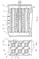
- mixer / heat exchanger tubes with outer webs or baffles are arranged one above the other in a U-shaped housing and welded both U-shaped housing shells to a sealed housing, so that forms a rectangular flow area for the product to be tempered ( Figure 2, 2a).
- Another user-friendly design of the mixer / heat exchanger is when tempering Stegrohrenden each in separate heating pockets, for the supply and discharge of the temperature, used, welded and unilaterally provided with a flange to be used as pluggable temperature control units in a customized housing.
- the stacked tubes with the single-sided distributor pockets can be pushed into tempered housings as plug-in units.
- there is a particularly large amount of heating surface in a small space so that a temperature-gentle temperature control takes place with a short residence time.
- a special advantage for the user is the possibility of cleaning the temperature-controlled mixer unit.
- mixers / heat exchangers can be arranged one behind the other, optionally in combination with known static mixers.
- the mixer / heat exchanger can thereby be arranged at an angle ⁇ of 45 to 135 °, for example of 90 ° to the housing center axis rotated to each other.
- the mixer / heat exchanger is a powerful tempering apparatus that provides high heat transfer performance even at laminar flow rates.
- the mixer / heat exchangers according to the invention are preferably suitable for the construction of backmixing-poor flow reactors, for carrying out exothermic and endothermic processes.
- a rapid heat exchange is desired and after dwell time regions which have less temperature-regulating effect and only a mixing is required is distinguished.
- Residence time ranges of flow reactors may be e.g. tempered tubes be used with known static mixers.
- the main application of the invention is in the field of gentle rapid tempering of viscous to highly viscous material systems.
- in addition to an effective temperature always a good and effective mixing is required to achieve temperature stability across the flow cross-section.
- additives or dyes can be mixed in so that additional mixing sections can be dispensed with in a process plant.
- entrainers can be metered directly into the melt, at the same time takes place by the effective temperature gentle gentle heating of the polymer to a higher temperature level, without initiating a thermal product damage, so that a downstream Evaporation step as a purification step, for example, a lower-boiling undesirable component, can be performed.
- mixers / heat exchangers can be used to design backmixing tube reactors. It can e.g. a reaction component over the additional feed of a preferred mixer / heat exchanger evenly distributed in the reaction space (product space). In endothermic reactions, the energy required for the reaction can be supplied directly in the course of the flow. If heat is generated during the reaction, the reaction heat can be dissipated directly when a refrigerant is added.
- small, compact high-performance heat exchangers for low-viscosity and high-viscosity, liquid and gaseous substances can be formed.
- the apparatuses show a very stable design, can be used due to the stable design at high pressure gradients, have a large heat transfer surface and work backmixing.
- the advantages are particularly noticeable due to small residence times.
- the flow behavior of very high-viscosity material systems implies a very high pressure drop, which is why only small flow velocities are economically possible.
- the expert speaks of creeping currents.
- the heat exchange between the heat transfer medium and the product is particularly bad.
- an intensive mixing process is necessary to achieve a gentle and uniform heating of the product.
- the temperature of the product is carried out with a corresponding arrangement of the tubes with very small residence time and a small residence time spectrum, so that in particular temperature-sensitive substances can be tempered with the mixer / heat exchanger according to the invention.
- the apparatus always works with small temperature differences between the inlet and outlet of the heat carrier or the coolant, so that a high power transfer when tempering and a very good use of secondary energy is possible.
- the invention enables compact, pressure-resistant and inexpensive heat transfer apparatuses or backmixing poor tube reactors.
- the form of plug-in mixer / heat exchanger units into appropriate tempered housings results in particularly easy-to-use appliances that allow easy cleaning.
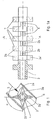
- the width of the web region is chosen here such that two web layers, each with two webs 2a, 2a 'and 2b, 2b', are arranged radially offset from one another in the housing 6 along the tube axis, and they adjoin each other without gaps in their axial extent (see FIG 1a).
- the shape or configuration of the webs and the web surface condition may be different.
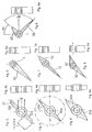
- the surface of the lands and the pipe may be structured by raised knobs, warts or grooves to increase the heat transferring area and to produce additional flow effects. Essentially, it depends on the process task or requirement. Examples are given in FIGS. 3 to 9.
- the webs may be arranged radially symmetrically (as in FIGS. 3-5) or also asymmetrically (FIGS. 7-9) on the outer circumference of the tube 1 and may show different angles relative to one another, it also being possible to combine different web shapes with one another and FIG -9 correspond with each other.
- the ridge shape may differ from the radial simple shape in that they additionally show a curved shape as a vane, which is particularly advantageous when the concentric regions intersect and secondary flows are forced.
- FIG. 3a show a cross-section or longitudinal section through a tube 1 similar to FIG. 1 with two webs 32a, 32a 'which have a constant diameter and have a flattening 31 transverse to the main flow direction 21 at their ends.
- the webs 42 a, 42 a ' are tapered in cross-section at the end.
- the webs 52a, 52a 'according to the variant of FIG. 5, 5a are similar to FIG. 4, but with widened foot according to the diameter of the tube 1 executed.
- Fig. 6 shows a variant of a web tube 1 similar to that of FIG. 5, but with only one web 62 'in a web position.
- the design according to FIG. 7 combines web shapes according to FIGS. 4 and 5 here with different radial extent of the webs 72, 72 '.
- Fig. 8 which is similar to Fig. 7, both webs 82, 82 'in cross-section and at an angle of 170 ° C are rotated around the tube axis to each other.
- the angular offset is 90 ° C., between the webs 92 and 92 'compared with the arrangement according to FIG. 7.
- the heat-transferring surface on the product-contacted side and also the flow around the pipe and thus the important mixing process can be favored.
- a defined arrangement of the webs on the outer circumference of the tube is useful to achieve in addition to the heat transfer and an effective mixing effect.
- the inner contour of the straw tubes 1, which is in contact with the temperature control can also be equipped with ribs. As a result, the heating surface is significantly increased on the heat or brine side.
- the tubular shape with any number or selectively arranged web areas on the outer pipe diameter can be produced economically by casting or in a forging process, thereby always ensures that there is a complete metallic contact between the pipe and raised outer contour.
- the radial webs may be hollow, so that the web cavity has a direct connection to the temperature control and everywhere constant wall thicknesses are present. Requirements regarding mechanical strength and required compressive strength are made by appropriate choice of wall thickness.
- the pipes can be made of different materials to ensure a sufficiently high corrosion resistance.
- the casting process allows economical production of only a specific pipe length. Larger pipe lengths must be made by connecting several pipe units with a suitable welding process.
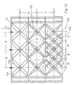
- FIG. 2 Another mixer / heat exchanger is shown in Figure 2 in longitudinal section.
- Six tubes 1 have two parallel layers of webs 2a and 2b, each with two radially offset webs 2a, 2a 'on the outer circumference of the tubes.
- the tubes 1 project with one end into a heat carrier feed chamber 4 and end in a heat transfer chamber 5 (FIG. 2a).
- the tubes 1 are welded to the supply 4 and the discharge chamber 5.
- the tubes 1 are at an angle ⁇ of about 5 degrees transverse to the main flow direction 21 of the product.
- the tubes 1 with the webs are positioned so that the webs are positioned at an angle ⁇ of 45 degrees to the product inlet 21.
- the webs 2a are offset to the webs 2b at an angle ⁇ of 90 degrees.
- the Zufiihrhunt 4 and discharge chamber 5 of the temperature control consist of a welded to the housing 6 pocket or a half pipe (not shown).
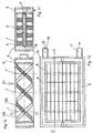
- FIG. 10 shows a mixer / heat exchanger unit, with a rectangular housing 6 and three strut tubes 1, 1 ', 1 ".
- the struts 12a, 12b correspond in their design to the types shown in FIG. 3 and are along the length of the tubes 1 , 1 ', 1 "arranged in an alternating position.
- FIG. 11 In the cross section in FIG. 11 along the line CC from FIG. 10, it can be seen that two chambers 4, 5 are formed by an outer casing 15, which chambers are connected to a supply line 16 or a discharge line 17 for a liquid heat carrier (see FIG 12).
- the tubes 1, 1 ', 1 "are flowed through by the heat transfer medium 18 during operation, as shown in Fig. 11. At their one end, the tubes 1, 1', 1" have a constriction 3 'in the channel 3.
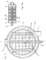
- the mixer / heat exchanger (see cross-sectional view in FIG. 12) has a rectangular product flow area formed by the housing 6.
- shaped mixer / heat exchanger units are arranged one behind the other in the flow direction and connected flush to a product line. The product flows through the units according to FIG. 10 from above (flow direction 21).
- Another way of supplying and discharging the heat transfer liquid is that around the heat exchanger housing with inner struts a ring or jacket tube, which in turn has two dividers to ensure a separation between flow and return of the heat carrier (see Figure 14), slipped and welded.
- a ring or jacket tube which in turn has two dividers to ensure a separation between flow and return of the heat carrier (see Figure 14), slipped and welded.
- the temperature-adjustable tubes 1 with their webs in the Anstrulbene of the product of different lengths.
- the web shape and direction, in conjunction with the horizontal pipe distances "a" or the vertical pipe distances "h” with each other form an optimal temperature-mixable mixer / heat exchanger geometry, with large heat transfer surface and high mixing effect.
- the tubes with the outer webs can show different pipe spacings, they can be chosen so narrow that the concentric web areas overlap and the outer mixing webs intersect with each other (see Figure 13). Thereby, the heat transferring area per unit volume can be varied and the residence time of the product can be reduced.
- the tubes in a plane can show different web shapes and arrangements.
- FIG. 13 shows a mixer heat exchanger arrangement similar to that shown in FIG. 10, but with two further rows of stanchions 131, 132 arranged one behind the other in the product flow direction 21.
- the first series of string tubes 1, 1 ', 1 "with webs 12 a, 12 b corresponds to the shape shown in Fig. 10.
- the tubes 131, 132 are arranged with the outer webs in such a way that the terminal webs in each case face the housing 6 in a defined gap in order to allow the flow tubes, in particular to the housing wall 6, to flow around as completely as possible (FIG. 13, level 2u ).
- This gap prevents the formation of dead spaces in the direction of flow, in which products can be deposited which reduce the quality of the products due to long temperature stress leads.
- the temperature-controllable mixers / heat exchangers can be used to distribute a component to be admixed uniformly in the product.
- small inlet openings 14 are introduced into the central tube 13 in the region of the webs 2a, 2b, which allow a politicianmischende component via a pipe extension (13) through the Schuffenraum to feed and uniformly introduced via the introduced openings 14 over the entire product flow cross-section ( Figure 14, 14a).
- a combination of several mixers / heat exchangers 9, 9a, 9b, 9c to form a flow reactor is shown schematically in section in FIG.
- the unit 9a here has an L / D ratio of 1.5 while the remaining units of the reactor have an L / D ratio of 0.75.
- the units are offset from each other by 90 degrees.
- the supplying heat transfer chambers 4 and dissipating town umankammem 5 of the mixer / heat exchanger units are all connected in parallel with the heat carrier supply.
- the tempering tubes 1 with webs are indicated in the units 9, 9b by broken lines and in the units 9a, 9c by the crossing points of the broken lines.
- the units in the horizontal and in the vertical plane or in the main flow direction 21 have different numbers of flow tubes for temperature control in order to effect a differentiated tempering and dispersing performance in the respective module.
- the central tube is open only on one side (similar to the embodiment in Figure 14a) and extended by a capillary 13 on one side by the tempering 4 until outside the mixer / heat exchanger unit 9.
- a metering pump the not shown in FIG. 15, can be connected to, for example, a further substance (additive, entrainment agent, reactants). over the entire flow cross-section of the module or the unit to dose and distribute. Holes or nozzles 14 along the tube in the product flow ensure a uniform distribution over the flow cross-section of the unit.
- the inner diameter 3 of the tube in the outlet region to the dissipative heat transfer chamber is reduced in short distance, e.g. on the inner diameter 3 ', similar to that shown in Figure 11. If steam is used as an energy source, this narrowing of the inner diameter 3 of the tube 1 is not required.
- Compact heat exchangers have the task in a short time a medium flowing through as high as possible, ie to heat as close to the heating medium temperature, so that due to a short-term temperature load no thermal damage to the product occurs.
- Compact heat exchangers should have smaller apparatus dimensions, as known heat exchangers with the same performance, so that in a process engineering system only a small space requirement and thus low installation and investment costs arise.
- An essential feature for comparing different types of heat exchangers is the heat transfer performance, the required heat exchange area and the product-side apparatus volume.
- the mixer / heat exchanger according to the invention was compared with a device from the prior art (Offenlegungsschrift DE-2 839 564 A1).
- the investigated mixer / heat exchanger according to the invention basically corresponded to the embodiment shown in FIGS. 2 and 2a with four rather than two tubes arranged side by side transversely of the product flow direction and overall nine instead of three seen in the flow direction 21 successively arranged tube packages (see Figure 2a).
- a highly viscous substance (silicone oil) with a viscosity of 10 Pa.s was selected as the product and pumped through the heat exchangers with a gear pump, so that the mass flow could be determined gravimetrically in the outlet area of the respective apparatus.
- the heat exchangers were connected to an electrically heated and regulated thermostat (heating power 3 kW) for the test. Water was chosen as the heat transfer medium so that the thermostat for the flow temperature at the thermostat was set to 90 ° C.
- the inlet and outlet temperature of the heat transfer medium and the product side were measured by means of a Pt-100 thermocouple and registered and stored on a data acquisition system.
- the apparatus data show constructive deviations. From Table 1 it can be seen that the mixer / heat exchanger has a shorter design and thus a lower product-side volume (hold-up). In addition, the mixer / heat exchanger has an effective heat transfer area of less than 0.01 square meters. Due to the design, a partial area of the housing is always tempered in the mixer / heat exchanger. For the evaluation of the test, the effective overall tempering surface has been used. From the experiments carried out, the measured temperatures and pressures, the characteristic characteristics were calculated and compared in Table 2 for both heat exchangers. The transferred heat output, the average heat transfer coefficient and the pressure loss were calculated from the recorded measured values.
- Table 2 shows the calculated performance data of the heat exchangers for a constant volume flow (silicone oil) of approx. 30 l / h. ⁇ b> ⁇ u> Table 2 ⁇ / u> ⁇ /b> Stand d. technology Mixer / heat exchanger Heat transfer performance 400W 520 W Product inlet temperature 22.6 ° C 22.5 ° C Product exit temperature 55.2 ° C 67.3 ° C Average heat transfer coefficient 98 W / sqm / K 160 W / sqm / K Pressure loss (product page) 1.5 bar 1 bar
- test result confirms a substantial improvement in the heat transfer performance with less residence time by the mixer / heat exchanger according to the invention.
Landscapes
- Engineering & Computer Science (AREA)
- Chemical & Material Sciences (AREA)
- General Engineering & Computer Science (AREA)
- Thermal Sciences (AREA)
- Physics & Mathematics (AREA)
- Mechanical Engineering (AREA)
- Chemical Kinetics & Catalysis (AREA)
- Civil Engineering (AREA)
- Structural Engineering (AREA)
- Dispersion Chemistry (AREA)
- Heat-Exchange Devices With Radiators And Conduit Assemblies (AREA)
- Accessories For Mixers (AREA)
- Physical Or Chemical Processes And Apparatus (AREA)
Claims (18)
- Mélangeur/échangeur de chaleur statique pour le traitement de produits visqueux et hautement visqueux, comprenant au moins un carter (6) à travers lequel on fait passer le produit, et au moins deux tubes (1) pouvant être tempérés, qui sont notamment pourvus d'un canal (3) dans lequel on fait passer un fluide caloporteur, le carter entourant les tubes (1) et un grand nombre d'ailettes d'échange de chaleur (2a, 2b) étant placées de manière répartie sur la périphérie des tubes (1),
caractérisé en ce que les ailettes d'échange de chaleur (2a, 2b), le long des tubes (1), sont orientées dans au moins deux couches parallèles (7, 8), et les ailettes (2a) et (2b) de couches (7, 8) voisines sont disposées de manière à être tournées mutuellement l'une par rapport à l'autre d'un angle α de 45° à 135°, de préférence de 70° à 110°, autour de l'axe du tube (1) portant les ailettes, et en ce que les ailettes (2a, 2b) forment par rapport à la direction d'écoulement principale (21) du produit à travers le carter (6), un angle β de ± 10° à ± 80°, et les tubes avec ailettes pouvant être tempérés sont placés côte à côte dans le carter, transversalement à la direction d'écoulement principale du produit. - Mélangeur/échangeur de chaleur selon la revendication 1, caractérisé en ce que pour chaque ailette (2a) respectivement (2b) d'une couche (7) respectivement (8), en regard de cette ailette, sur le tube (1), est disposée une ailette opposée (2a') respectivement (2b').
- Mélangeur/échangeur de chaleur selon la revendication 1 ou 2, caractérisé en ce que les ailettes (2a) ou (2b) des différentes couches (7) ou (8) sont disposées de manière alternée, vu sur la longueur du tube (1).
- Mélangeur/échangeur de chaleur selon l'une des revendications 1 à 3, caractérisé en ce que l'angle α entre les ailettes des différentes couches (7, 8) vaut de 85 à 95°.
- Mélangeur/échangeur de chaleur selon l'une des revendications 1 à 4, caractérisé en ce que le carter (6) présente des conduites d'amenée (4) et des conduites d'évacuation (5) pour un fluide caloporteur, qui sont reliées à l'entrée et respectivement la sortie des canaux (3, 3').
- Mélangeur/échangeur de chaleur selon l'une des revendications 1 à 5, caractérisé en ce que dans le carter (6) sont placés, dans plusieurs plans successifs, des tubes (1, 1') pourvus d'ailettes (2a, 2b).
- Mélangeur/échangeur de chaleur selon l'une des revendications 1 à 6, caractérisé en ce que l'étendue radiale des ailettes (2a, 2b) respectivement voisines disposées sur des tubes (132, 132') voisins, se chevauche.
- Mélangeur/échangeur de chaleur selon l'une des revendications 1 à 7, caractérisé en ce que les ailettes (2a, 2b) des différentes couches (7, 8) le long des tubes (1, 1', 1") sont disposées mutuellement en quinconce.
- Mélangeur/échangeur de chaleur selon l'une des revendications 1 à 8, caractérisé en ce que l'étendue radiale des ailettes (2a, 2b) vaut au moins 0,5 fois le diamètre intérieur du tube (1) qui y est lié.
- Mélangeur/échangeur de chaleur selon l'une des revendications 1 à 9, caractérisé en ce que la paroi intérieure des tubes (1, 1') présente un contour destiné à augmenter sa surface, notamment sous la forme de nervures longitudinales.
- Mélangeur/échangeur de chaleur selon l'une des revendications 1 à 10, caractérisé en ce que des ailettes sélectionnées (2a, 2a', 2b, 2b') des tubes (1) sont d'une configuration creuse, et la cavité correspondante est en communication avec le canal (3) du tube (1).
- Mélangeur/échangeur de chaleur selon l'une des revendications 1 à 11, caractérisé en ce que les tubes (1, 1', 1") sont munis d'un chauffage à résistance ou d'un élément de refroidissement électrique.
- Mélangeur/échangeur de chaleur selon l'une des revendications 1 à 12, caractérisé en ce que les tubes (1, 1', 1") et/ou les ailettes (2a, 2b) sont revêtus d'un catalyseur.
- Mélangeur/échangeur de chaleur selon l'une des revendications 1 à 13, caractérisé en ce que les tubes (1, 1', 1'') sont disposés dans le carter (6) dans une direction transversale à la direction d'écoulement principale du produit, sous un angle γ d'au plus +/-15°.
- Mélangeur/échangeur de chaleur selon l'une des revendications 1 à 14, caractérisé en ce que dans le carter (6) sont placés, dans plusieurs plans successifs, des tubes (1, 1a) munis d'ailettes (2a, 2b), et les tubes (1) des plans présentent des ailettes (2a, 2b) dimensionnées de manière différente par rapport aux ailettes des tubes (1a) du plan voisin.
- Mélangeur/échangeur de chaleur selon l'une des revendications 1 à 15, caractérisé en ce que le mélangeur/échangeur de chaleur comporte au moins un tube d'introduction de produit ou de substance disposé parallèlement aux tubes (1), qui est pourvu d'ailettes (2a, 2b) de même type et présente plusieurs ouvertures (14) vers l'intérieur du carter (6).
- Mélangeur/échangeur de chaleur selon l'une des revendications 1 à 16, caractérisé en ce que les tubes (1) présentent des canaux (3) dans la zone de sortie d'écoulement desquels est placée une buse (3') de diamètre réduit par rapport à celui des canaux (3).
- Utilisation des mélangeurs/échangeurs de chaleur selon l'une des revendications 1 à 17, pour tempérer des systèmes de substances ou de produits présentant une viscosité de 0,001 à 20 000 Pa.s.
Applications Claiming Priority (2)
| Application Number | Priority Date | Filing Date | Title |
|---|---|---|---|
| DE10233506A DE10233506B4 (de) | 2002-07-24 | 2002-07-24 | Mischer/Wärmeaustauscher |
| DE10233506 | 2002-07-24 |
Publications (2)
| Publication Number | Publication Date |
|---|---|
| EP1384502A1 EP1384502A1 (fr) | 2004-01-28 |
| EP1384502B1 true EP1384502B1 (fr) | 2006-01-11 |
Family
ID=29796539
Family Applications (1)
| Application Number | Title | Priority Date | Filing Date |
|---|---|---|---|
| EP03015959A Expired - Lifetime EP1384502B1 (fr) | 2002-07-24 | 2003-07-14 | Mélangeur, échangeur de chaleur |
Country Status (6)
| Country | Link |
|---|---|
| US (1) | US7220048B2 (fr) |
| EP (1) | EP1384502B1 (fr) |
| JP (1) | JP4430347B2 (fr) |
| AT (1) | ATE315434T1 (fr) |
| DE (2) | DE10233506B4 (fr) |
| ES (1) | ES2256622T3 (fr) |
Cited By (1)
| Publication number | Priority date | Publication date | Assignee | Title |
|---|---|---|---|---|
| DE102011085944A1 (de) | 2010-11-10 | 2012-05-10 | Bayer Materialscience Aktiengesellschaft | Verfahren zur kontinuierlichen Herstellung von thermoplastisch verarbeitbaren Polyurethanen |
Families Citing this family (50)
| Publication number | Priority date | Publication date | Assignee | Title |
|---|---|---|---|---|
| US7622094B2 (en) * | 2004-11-19 | 2009-11-24 | Larry Lewis | Method of recovering energy using a catalytic finned heat exchanger |
| US7587901B2 (en) | 2004-12-20 | 2009-09-15 | Amerigon Incorporated | Control system for thermal module in vehicle |
| JP4989062B2 (ja) * | 2005-04-28 | 2012-08-01 | バブコック日立株式会社 | 流体混合装置 |
| US20090038701A1 (en) | 2006-01-17 | 2009-02-12 | Baxter International Inc. | Device, system and method for mixing |
| US20080087316A1 (en) | 2006-10-12 | 2008-04-17 | Masa Inaba | Thermoelectric device with internal sensor |
| JP5080779B2 (ja) * | 2006-10-25 | 2012-11-21 | テルモ株式会社 | リポソーム製剤の製造方法 |
| US8143554B2 (en) | 2007-03-16 | 2012-03-27 | Amerigon Incorporated | Air warmer |
| EP2150765B1 (fr) * | 2007-05-24 | 2011-02-16 | Atlas Holding AG | Canal d'écoulement pour un échangeur de chaleur mélangeur |
| DE102007038332A1 (de) * | 2007-08-14 | 2009-02-19 | Wacker Chemie Ag | Kontinuierliches Polymerisationsverfahren |
| DE102007040850A1 (de) * | 2007-08-29 | 2009-03-05 | Wacker Chemie Ag | Verfahren zur Herstellung von Schutzkolloid-stabilisierten Polymerisaten und Vorrichtung zur Durchführung des Verfahrens |
| US7877827B2 (en) | 2007-09-10 | 2011-02-01 | Amerigon Incorporated | Operational control schemes for ventilated seat or bed assemblies |
| US7887764B2 (en) * | 2007-09-18 | 2011-02-15 | Jernberg Gary R | Mixer with a catalytic surface |
| EP2042284B1 (fr) * | 2007-09-27 | 2011-08-03 | Sulzer Chemtech AG | Dispositif destiné à la production d'un mélange pouvant s'écouler et réagir et son utilisation |
| KR101779870B1 (ko) | 2008-02-01 | 2017-10-10 | 젠썸 인코포레이티드 | 열전 소자용 응결 센서 및 습도 센서 |
| FR2929856B1 (fr) * | 2008-04-15 | 2010-08-20 | Rhodia Operations | Procede de preparation de cristaux a base d'un ester d'acide gras |
| JP5997899B2 (ja) | 2008-07-18 | 2016-09-28 | ジェンサーム インコーポレイテッドGentherm Incorporated | 空調されるベッドアセンブリ |
| US8575518B2 (en) * | 2009-01-28 | 2013-11-05 | Gentherm Incorporated | Convective heater |
| CN101762189B (zh) * | 2010-03-11 | 2011-06-22 | 刘小江 | 一种逆流管排式间壁式换热器 |
| US9121414B2 (en) | 2010-11-05 | 2015-09-01 | Gentherm Incorporated | Low-profile blowers and methods |
| US20120127820A1 (en) * | 2010-11-23 | 2012-05-24 | Noles Jr Jerry W | Polymer Blending System |
| US8905627B2 (en) * | 2010-11-23 | 2014-12-09 | Jerry W. Noles, Jr. | Polymer blending system |
| EP2565572A1 (fr) * | 2011-09-02 | 2013-03-06 | Aurotec GmbH | Système de conduits d'échangeur thermique |
| WO2013052823A1 (fr) | 2011-10-07 | 2013-04-11 | Gentherm Incorporated | Commandes de dispositif thermoélectrique et procédés associés |
| JP5901361B2 (ja) * | 2011-11-18 | 2016-04-06 | 住友化学株式会社 | 連続重合装置および重合体組成物の製造方法 |
| US9989267B2 (en) | 2012-02-10 | 2018-06-05 | Gentherm Incorporated | Moisture abatement in heating operation of climate controlled systems |
| DE102012005513A1 (de) * | 2012-03-19 | 2013-09-19 | Bundy Refrigeration Gmbh | Wärmetauscher, Verfahren zu seiner Herstellung sowie verschiedene Anlagen mit einem derartigen Wärmetauscher |
| JP5984702B2 (ja) * | 2013-01-31 | 2016-09-06 | 住友化学株式会社 | 連続重合装置および重合体組成物の製造方法 |
| US20150087733A1 (en) | 2013-09-20 | 2015-03-26 | Rolf Heusser | Method for the Manufacture of Foams of Low Density |
| US9777973B2 (en) | 2013-09-20 | 2017-10-03 | Promix Solutions Ag | Device for mixing and heat exchange |
| US9662962B2 (en) | 2013-11-05 | 2017-05-30 | Gentherm Incorporated | Vehicle headliner assembly for zonal comfort |
| KR102252584B1 (ko) | 2014-02-14 | 2021-05-14 | 젠썸 인코포레이티드 | 전도식 대류식 기온 제어 조립체 |
| CN105264296A (zh) * | 2014-05-09 | 2016-01-20 | 生态工厂有限公司 | 空调装置 |
| US11857004B2 (en) | 2014-11-14 | 2024-01-02 | Gentherm Incorporated | Heating and cooling technologies |
| US11033058B2 (en) | 2014-11-14 | 2021-06-15 | Gentherm Incorporated | Heating and cooling technologies |
| US11639816B2 (en) | 2014-11-14 | 2023-05-02 | Gentherm Incorporated | Heating and cooling technologies including temperature regulating pad wrap and technologies with liquid system |
| US9572555B1 (en) * | 2015-09-24 | 2017-02-21 | Ethicon, Inc. | Spray or drip tips having multiple outlet channels |
| EP3489603B1 (fr) | 2017-11-28 | 2021-06-16 | Promix Solutions AG | Echangeur de chaleur |
| JP6961224B2 (ja) * | 2017-12-28 | 2021-11-05 | ホクシン産業株式会社 | 燃料油移送装置 |
| US11223004B2 (en) | 2018-07-30 | 2022-01-11 | Gentherm Incorporated | Thermoelectric device having a polymeric coating |
| CN121230238A (zh) | 2018-11-30 | 2025-12-30 | 金瑟姆股份公司 | 热电调节系统和方法 |
| US11152557B2 (en) | 2019-02-20 | 2021-10-19 | Gentherm Incorporated | Thermoelectric module with integrated printed circuit board |
| DE102019009099A1 (de) * | 2019-12-31 | 2021-07-01 | Heinz Gross | Wärmetauscher mit Mischfunktion |
| CN112179176B (zh) * | 2020-09-24 | 2022-01-14 | 金湖正泓企业策划有限公司 | 一种基于高密度管道换热用分流式换热器 |
| US12552223B2 (en) | 2021-03-18 | 2026-02-17 | Gentherm Incorporated | Optimal control of convective thermal devices |
| US12611909B2 (en) | 2021-03-18 | 2026-04-28 | Gentherm Incorporated | Preconditioning surfaces using intelligent thermal effectors |
| CN113916037A (zh) * | 2021-10-13 | 2022-01-11 | 江苏科技大学 | 雪花状翅片相变蓄热装置 |
| JP7738496B2 (ja) * | 2022-02-04 | 2025-09-12 | 三菱重工業株式会社 | 熱交換器 |
| CN114887551B (zh) * | 2022-05-30 | 2025-07-22 | 浙江力久环境科技有限公司 | 混合器反应器的液相加料结构 |
| CN119836315A (zh) * | 2022-09-06 | 2025-04-15 | 巴斯夫欧洲公司 | 具有至少一个挡板的不连续操作的凝华器 |
| DE102024209125A1 (de) | 2024-09-23 | 2026-03-26 | Technische Universität Dresden, Körperschaft des öffentlichen Rechts | Statischer Mischer mit integrierter elektrischer Leiterbahn |
Family Cites Families (15)
| Publication number | Priority date | Publication date | Assignee | Title |
|---|---|---|---|---|
| BE465451A (fr) * | ||||
| US1921927A (en) * | 1929-08-01 | 1933-08-08 | Griscom Russell Co | Fin tubing |
| GB521548A (en) * | 1938-10-18 | 1940-05-24 | Edward Frank Spanner | Improvements in tubular heat exchange apparatus |
| US2322341A (en) * | 1940-01-27 | 1943-06-22 | Morris F Booth | Heat exchange unit |
| GB569000A (en) * | 1946-01-18 | 1945-04-30 | Edward Frank Spanner | Improvements in tubes for heat exchange apparatus |
| DE836946C (de) * | 1947-09-19 | 1952-04-17 | Andre Huet | Gegenstrom-Waermeaustauscher |
| US3111168A (en) * | 1954-11-24 | 1963-11-19 | Huet Andre | Heat exchangers |
| JPS5716319B2 (fr) * | 1973-09-03 | 1982-04-03 | ||
| DE2839564C2 (de) * | 1978-09-12 | 1982-10-21 | Hoechst Ag, 6000 Frankfurt | Vorrichtung mit Zu- und Abfuhr von Wärme und zum Mischen von flüssigen Medien |
| US4877087A (en) * | 1984-08-16 | 1989-10-31 | Sundstrand Heat Transfer, Inc. | Segmented fin heat exchanger core |
| US4865460A (en) * | 1988-05-02 | 1989-09-12 | Kama Corporation | Static mixing device |
| EP0526393B1 (fr) * | 1991-07-30 | 1996-08-28 | Sulzer Chemtech AG | dispositif d'immixtion |
| US5472047A (en) * | 1993-09-20 | 1995-12-05 | Brown Fintube | Mixed finned tube and bare tube heat exchanger tube bundle |
| DE19837671A1 (de) * | 1998-08-20 | 2000-02-24 | Bayer Ag | Statischer Mischer |
| EP1067352B1 (fr) * | 1999-07-07 | 2003-08-27 | Fluitec Georg AG | Dispositif d'echange de chaleur |
-
2002
- 2002-07-24 DE DE10233506A patent/DE10233506B4/de not_active Expired - Lifetime
-
2003
- 2003-07-14 AT AT03015959T patent/ATE315434T1/de not_active IP Right Cessation
- 2003-07-14 DE DE50302165T patent/DE50302165D1/de not_active Expired - Lifetime
- 2003-07-14 EP EP03015959A patent/EP1384502B1/fr not_active Expired - Lifetime
- 2003-07-14 ES ES03015959T patent/ES2256622T3/es not_active Expired - Lifetime
- 2003-07-18 US US10/622,625 patent/US7220048B2/en not_active Expired - Fee Related
- 2003-07-24 JP JP2003201315A patent/JP4430347B2/ja not_active Expired - Fee Related
Cited By (1)
| Publication number | Priority date | Publication date | Assignee | Title |
|---|---|---|---|---|
| DE102011085944A1 (de) | 2010-11-10 | 2012-05-10 | Bayer Materialscience Aktiengesellschaft | Verfahren zur kontinuierlichen Herstellung von thermoplastisch verarbeitbaren Polyurethanen |
Also Published As
| Publication number | Publication date |
|---|---|
| US20040085853A1 (en) | 2004-05-06 |
| ATE315434T1 (de) | 2006-02-15 |
| ES2256622T3 (es) | 2006-07-16 |
| US7220048B2 (en) | 2007-05-22 |
| DE10233506B4 (de) | 2004-12-09 |
| DE10233506A1 (de) | 2004-02-12 |
| EP1384502A1 (fr) | 2004-01-28 |
| JP4430347B2 (ja) | 2010-03-10 |
| JP2004058058A (ja) | 2004-02-26 |
| DE50302165D1 (de) | 2006-04-06 |
Similar Documents
| Publication | Publication Date | Title |
|---|---|---|
| EP1384502B1 (fr) | Mélangeur, échangeur de chaleur | |
| EP2052199B1 (fr) | Appareil combiné d'échange de chaleur et de mélange statique avec un liquide | |
| EP1486749B1 (fr) | Turbulateur | |
| EP2349552B1 (fr) | Réacteur modulaire | |
| EP0417428B1 (fr) | Echangeur de chaleur à faisceau tubulaire | |
| EP2851118B1 (fr) | Dispositif de mélange et d'échange thermique et procédé pour sa fabrication | |
| EP3585509B1 (fr) | Échangeur de chaleur et réacteur | |
| EP1569745B1 (fr) | Reacteur tubulaire a enveloppe pour des reactions catalytiques en phase gazeuse | |
| EP1586370B1 (fr) | Ensemble réacteur destiné à la mise en oeuvre de réactions catalytiques en phase gazeuse | |
| DE60023394T2 (de) | Wärmetauscher | |
| EP3489603A1 (fr) | Echangeur de chaleur | |
| EP1890785B1 (fr) | Évaporateur compact complet | |
| EP1681091B1 (fr) | Reacteur tubulaire pour effectuer des reactions exothermes ou endothermes | |
| EP0810414B1 (fr) | Echangeur de chaleur pour le refroidissement de gaz de craquage | |
| DE2536657C3 (de) | Wärmeaustauscher zum Vorwärmen von Verbrennungsluft für insbesondere ölbeheizte Industrieöfen | |
| EP0722075A1 (fr) | Echangeur de chaleur à tubes capillaires de haute capacité | |
| DE2149536A1 (de) | Verfahren zum Erhitzen einer Waermeuebertragungsfluessigkeit | |
| EP3822569B1 (fr) | Echangeur de chaleur | |
| EP3966513B1 (fr) | Échangeur de chaleur à faisceau tubulaire comportant des modules/éléments intégrés constitués de surfaces déflectrices et de barrettes de guidage | |
| EP1995545B1 (fr) | Appareil à plaques pour processus de transmission thermique | |
| EP4089357B1 (fr) | Echangeur de chaleur | |
| DE3000714A1 (de) | Vorrichtung zum gleichmaessigen verteilen eines heiz- oder kuehlmittels in einem katalytischen reaktionsraum | |
| DE19622139A1 (de) | Wärmetauscher zum Kühlen von Spaltgas | |
| DE19852894B4 (de) | Verfahren zur Gewinnung von Phthalsäureanhydrid durch katalytische Gasphasenreaktion und Vorrichtung zur Durchführung des Verfahrens | |
| DE3036334C2 (de) | Wärmeübertrager |
Legal Events
| Date | Code | Title | Description |
|---|---|---|---|
| PUAI | Public reference made under article 153(3) epc to a published international application that has entered the european phase |
Free format text: ORIGINAL CODE: 0009012 |
|
| AK | Designated contracting states |
Kind code of ref document: A1 Designated state(s): AT BE BG CH CY CZ DE DK EE ES FI FR GB GR HU IE IT LI LU MC NL PT RO SE SI SK TR |
|
| AX | Request for extension of the european patent |
Extension state: AL LT LV MK |
|
| RAP1 | Party data changed (applicant data changed or rights of an application transferred) |
Owner name: BAYER TECHNOLOGY SERVICES GMBH |
|
| 17P | Request for examination filed |
Effective date: 20040728 |
|
| 17Q | First examination report despatched |
Effective date: 20040827 |
|
| AKX | Designation fees paid |
Designated state(s): AT BE BG CH CY CZ DE DK EE ES FI FR GB GR HU IE IT LI LU MC NL PT RO SE SI SK TR |
|
| GRAP | Despatch of communication of intention to grant a patent |
Free format text: ORIGINAL CODE: EPIDOSNIGR1 |
|
| GRAS | Grant fee paid |
Free format text: ORIGINAL CODE: EPIDOSNIGR3 |
|
| GRAA | (expected) grant |
Free format text: ORIGINAL CODE: 0009210 |
|
| AK | Designated contracting states |
Kind code of ref document: B1 Designated state(s): AT BE BG CH CY CZ DE DK EE ES FI FR GB GR HU IE IT LI LU MC NL PT RO SE SI SK TR |
|
| PG25 | Lapsed in a contracting state [announced via postgrant information from national office to epo] |
Ref country code: SK Free format text: LAPSE BECAUSE OF FAILURE TO SUBMIT A TRANSLATION OF THE DESCRIPTION OR TO PAY THE FEE WITHIN THE PRESCRIBED TIME-LIMIT Effective date: 20060111 Ref country code: RO Free format text: LAPSE BECAUSE OF FAILURE TO SUBMIT A TRANSLATION OF THE DESCRIPTION OR TO PAY THE FEE WITHIN THE PRESCRIBED TIME-LIMIT Effective date: 20060111 Ref country code: FI Free format text: LAPSE BECAUSE OF FAILURE TO SUBMIT A TRANSLATION OF THE DESCRIPTION OR TO PAY THE FEE WITHIN THE PRESCRIBED TIME-LIMIT Effective date: 20060111 Ref country code: SI Free format text: LAPSE BECAUSE OF FAILURE TO SUBMIT A TRANSLATION OF THE DESCRIPTION OR TO PAY THE FEE WITHIN THE PRESCRIBED TIME-LIMIT Effective date: 20060111 Ref country code: IE Free format text: LAPSE BECAUSE OF FAILURE TO SUBMIT A TRANSLATION OF THE DESCRIPTION OR TO PAY THE FEE WITHIN THE PRESCRIBED TIME-LIMIT Effective date: 20060111 |
|
| REG | Reference to a national code |
Ref country code: CH Ref legal event code: EP |
|
| REG | Reference to a national code |
Ref country code: IE Ref legal event code: FG4D Free format text: LANGUAGE OF EP DOCUMENT: GERMAN |
|
| REG | Reference to a national code |
Ref country code: CH Ref legal event code: NV Representative=s name: E. BLUM & CO. PATENTANWAELTE |
|
| GBT | Gb: translation of ep patent filed (gb section 77(6)(a)/1977) |
Effective date: 20060309 |
|
| REF | Corresponds to: |
Ref document number: 50302165 Country of ref document: DE Date of ref document: 20060406 Kind code of ref document: P |
|
| PG25 | Lapsed in a contracting state [announced via postgrant information from national office to epo] |
Ref country code: BG Free format text: LAPSE BECAUSE OF FAILURE TO SUBMIT A TRANSLATION OF THE DESCRIPTION OR TO PAY THE FEE WITHIN THE PRESCRIBED TIME-LIMIT Effective date: 20060411 Ref country code: DK Free format text: LAPSE BECAUSE OF FAILURE TO SUBMIT A TRANSLATION OF THE DESCRIPTION OR TO PAY THE FEE WITHIN THE PRESCRIBED TIME-LIMIT Effective date: 20060411 Ref country code: SE Free format text: LAPSE BECAUSE OF FAILURE TO SUBMIT A TRANSLATION OF THE DESCRIPTION OR TO PAY THE FEE WITHIN THE PRESCRIBED TIME-LIMIT Effective date: 20060411 |
|
| PG25 | Lapsed in a contracting state [announced via postgrant information from national office to epo] |
Ref country code: PT Free format text: LAPSE BECAUSE OF FAILURE TO SUBMIT A TRANSLATION OF THE DESCRIPTION OR TO PAY THE FEE WITHIN THE PRESCRIBED TIME-LIMIT Effective date: 20060612 |
|
| REG | Reference to a national code |
Ref country code: ES Ref legal event code: FG2A Ref document number: 2256622 Country of ref document: ES Kind code of ref document: T3 |
|
| PG25 | Lapsed in a contracting state [announced via postgrant information from national office to epo] |
Ref country code: MC Free format text: LAPSE BECAUSE OF NON-PAYMENT OF DUE FEES Effective date: 20060731 |
|
| REG | Reference to a national code |
Ref country code: IE Ref legal event code: FD4D |
|
| ET | Fr: translation filed | ||
| PLBE | No opposition filed within time limit |
Free format text: ORIGINAL CODE: 0009261 |
|
| STAA | Information on the status of an ep patent application or granted ep patent |
Free format text: STATUS: NO OPPOSITION FILED WITHIN TIME LIMIT |
|
| 26N | No opposition filed |
Effective date: 20061012 |
|
| REG | Reference to a national code |
Ref country code: CH Ref legal event code: PFA Owner name: BAYER TECHNOLOGY SERVICES GMBH Free format text: BAYER TECHNOLOGY SERVICES GMBH# #51368 LEVERKUSEN (DE) -TRANSFER TO- BAYER TECHNOLOGY SERVICES GMBH# #51368 LEVERKUSEN (DE) |
|
| PG25 | Lapsed in a contracting state [announced via postgrant information from national office to epo] |
Ref country code: AT Free format text: LAPSE BECAUSE OF NON-PAYMENT OF DUE FEES Effective date: 20060714 |
|
| PG25 | Lapsed in a contracting state [announced via postgrant information from national office to epo] |
Ref country code: CZ Free format text: LAPSE BECAUSE OF FAILURE TO SUBMIT A TRANSLATION OF THE DESCRIPTION OR TO PAY THE FEE WITHIN THE PRESCRIBED TIME-LIMIT Effective date: 20060111 Ref country code: GR Free format text: LAPSE BECAUSE OF FAILURE TO SUBMIT A TRANSLATION OF THE DESCRIPTION OR TO PAY THE FEE WITHIN THE PRESCRIBED TIME-LIMIT Effective date: 20060412 |
|
| PG25 | Lapsed in a contracting state [announced via postgrant information from national office to epo] |
Ref country code: EE Free format text: LAPSE BECAUSE OF FAILURE TO SUBMIT A TRANSLATION OF THE DESCRIPTION OR TO PAY THE FEE WITHIN THE PRESCRIBED TIME-LIMIT Effective date: 20060111 |
|
| PG25 | Lapsed in a contracting state [announced via postgrant information from national office to epo] |
Ref country code: LU Free format text: LAPSE BECAUSE OF NON-PAYMENT OF DUE FEES Effective date: 20060714 Ref country code: TR Free format text: LAPSE BECAUSE OF FAILURE TO SUBMIT A TRANSLATION OF THE DESCRIPTION OR TO PAY THE FEE WITHIN THE PRESCRIBED TIME-LIMIT Effective date: 20060111 Ref country code: HU Free format text: LAPSE BECAUSE OF FAILURE TO SUBMIT A TRANSLATION OF THE DESCRIPTION OR TO PAY THE FEE WITHIN THE PRESCRIBED TIME-LIMIT Effective date: 20060712 |
|
| PG25 | Lapsed in a contracting state [announced via postgrant information from national office to epo] |
Ref country code: CY Free format text: LAPSE BECAUSE OF FAILURE TO SUBMIT A TRANSLATION OF THE DESCRIPTION OR TO PAY THE FEE WITHIN THE PRESCRIBED TIME-LIMIT Effective date: 20060111 |
|
| REG | Reference to a national code |
Ref country code: NL Ref legal event code: SD Effective date: 20121228 |
|
| REG | Reference to a national code |
Ref country code: FR Ref legal event code: TP Owner name: BAYER INTELLECTUAL PROPERTY GMBH, DE Effective date: 20130109 |
|
| REG | Reference to a national code |
Ref country code: ES Ref legal event code: PC2A Owner name: BAYER INTELLECTUAL PROPERTY GMBH Effective date: 20130319 |
|
| REG | Reference to a national code |
Ref country code: DE Ref legal event code: R081 Ref document number: 50302165 Country of ref document: DE Owner name: BAYER INTELLECTUAL PROPERTY GMBH, DE Free format text: FORMER OWNER: BAYER TECHNOLOGY SERVICES GMBH, 51373 LEVERKUSEN, DE Effective date: 20130226 |
|
| REG | Reference to a national code |
Ref country code: CH Ref legal event code: PUE Owner name: BAYER INTELLECTUAL PROPERTY GMBH, DE Free format text: FORMER OWNER: BAYER TECHNOLOGY SERVICES GMBH, DE |
|
| PGFP | Annual fee paid to national office [announced via postgrant information from national office to epo] |
Ref country code: IT Payment date: 20130626 Year of fee payment: 11 |
|
| PGFP | Annual fee paid to national office [announced via postgrant information from national office to epo] |
Ref country code: BE Payment date: 20130712 Year of fee payment: 11 Ref country code: DE Payment date: 20130711 Year of fee payment: 11 Ref country code: ES Payment date: 20130628 Year of fee payment: 11 Ref country code: NL Payment date: 20130716 Year of fee payment: 11 Ref country code: CH Payment date: 20130712 Year of fee payment: 11 |
|
| PGFP | Annual fee paid to national office [announced via postgrant information from national office to epo] |
Ref country code: FR Payment date: 20130724 Year of fee payment: 11 Ref country code: GB Payment date: 20130710 Year of fee payment: 11 |
|
| REG | Reference to a national code |
Ref country code: GB Ref legal event code: 732E Free format text: REGISTERED BETWEEN 20140206 AND 20140212 |
|
| REG | Reference to a national code |
Ref country code: DE Ref legal event code: R119 Ref document number: 50302165 Country of ref document: DE |
|
| REG | Reference to a national code |
Ref country code: NL Ref legal event code: V1 Effective date: 20150201 |
|
| REG | Reference to a national code |
Ref country code: CH Ref legal event code: PL |
|
| GBPC | Gb: european patent ceased through non-payment of renewal fee |
Effective date: 20140714 |
|
| PG25 | Lapsed in a contracting state [announced via postgrant information from national office to epo] |
Ref country code: NL Free format text: LAPSE BECAUSE OF NON-PAYMENT OF DUE FEES Effective date: 20150201 |
|
| REG | Reference to a national code |
Ref country code: FR Ref legal event code: ST Effective date: 20150331 |
|
| PG25 | Lapsed in a contracting state [announced via postgrant information from national office to epo] |
Ref country code: CH Free format text: LAPSE BECAUSE OF NON-PAYMENT OF DUE FEES Effective date: 20140731 Ref country code: DE Free format text: LAPSE BECAUSE OF NON-PAYMENT OF DUE FEES Effective date: 20150203 Ref country code: LI Free format text: LAPSE BECAUSE OF NON-PAYMENT OF DUE FEES Effective date: 20140731 Ref country code: IT Free format text: LAPSE BECAUSE OF NON-PAYMENT OF DUE FEES Effective date: 20140714 |
|
| REG | Reference to a national code |
Ref country code: DE Ref legal event code: R119 Ref document number: 50302165 Country of ref document: DE Effective date: 20150203 |
|
| PG25 | Lapsed in a contracting state [announced via postgrant information from national office to epo] |
Ref country code: GB Free format text: LAPSE BECAUSE OF NON-PAYMENT OF DUE FEES Effective date: 20140714 Ref country code: FR Free format text: LAPSE BECAUSE OF NON-PAYMENT OF DUE FEES Effective date: 20140731 |
|
| REG | Reference to a national code |
Ref country code: ES Ref legal event code: FD2A Effective date: 20150826 |
|
| PG25 | Lapsed in a contracting state [announced via postgrant information from national office to epo] |
Ref country code: ES Free format text: LAPSE BECAUSE OF NON-PAYMENT OF DUE FEES Effective date: 20140715 |
|
| PG25 | Lapsed in a contracting state [announced via postgrant information from national office to epo] |
Ref country code: BE Free format text: LAPSE BECAUSE OF NON-PAYMENT OF DUE FEES Effective date: 20140731 |