EP1384638A2 - Méthode et dispositif de surveillance de l'état d'usure et/ou de fonctionnement de garnitures et/ou disques de frein d'un véhicule - Google Patents
Méthode et dispositif de surveillance de l'état d'usure et/ou de fonctionnement de garnitures et/ou disques de frein d'un véhicule Download PDFInfo
- Publication number
- EP1384638A2 EP1384638A2 EP03015521A EP03015521A EP1384638A2 EP 1384638 A2 EP1384638 A2 EP 1384638A2 EP 03015521 A EP03015521 A EP 03015521A EP 03015521 A EP03015521 A EP 03015521A EP 1384638 A2 EP1384638 A2 EP 1384638A2
- Authority
- EP
- European Patent Office
- Prior art keywords
- wear
- brake
- temperature
- limit
- braking
- Prior art date
- Legal status (The legal status is an assumption and is not a legal conclusion. Google has not performed a legal analysis and makes no representation as to the accuracy of the status listed.)
- Granted
Links
- 238000000034 method Methods 0.000 title claims abstract description 45
- 238000012544 monitoring process Methods 0.000 title claims abstract description 9
- 230000008569 process Effects 0.000 claims abstract description 20
- 238000011156 evaluation Methods 0.000 claims description 26
- 238000001514 detection method Methods 0.000 claims description 19
- 239000000463 material Substances 0.000 claims description 8
- 239000004020 conductor Substances 0.000 claims description 5
- 230000006870 function Effects 0.000 claims description 5
- 230000001419 dependent effect Effects 0.000 claims description 4
- 238000005520 cutting process Methods 0.000 claims description 2
- 238000012423 maintenance Methods 0.000 description 9
- 238000005259 measurement Methods 0.000 description 3
- 230000003287 optical effect Effects 0.000 description 3
- 230000001186 cumulative effect Effects 0.000 description 2
- 238000011161 development Methods 0.000 description 2
- 230000018109 developmental process Effects 0.000 description 2
- 238000004519 manufacturing process Methods 0.000 description 2
- 230000005855 radiation Effects 0.000 description 2
- 239000008186 active pharmaceutical agent Substances 0.000 description 1
- 230000008859 change Effects 0.000 description 1
- 230000006378 damage Effects 0.000 description 1
- 238000001454 recorded image Methods 0.000 description 1
- 230000001105 regulatory effect Effects 0.000 description 1
- 238000003860 storage Methods 0.000 description 1
- 238000012549 training Methods 0.000 description 1
Images

Classifications
-
- F—MECHANICAL ENGINEERING; LIGHTING; HEATING; WEAPONS; BLASTING
- F16—ENGINEERING ELEMENTS AND UNITS; GENERAL MEASURES FOR PRODUCING AND MAINTAINING EFFECTIVE FUNCTIONING OF MACHINES OR INSTALLATIONS; THERMAL INSULATION IN GENERAL
- F16D—COUPLINGS FOR TRANSMITTING ROTATION; CLUTCHES; BRAKES
- F16D55/00—Brakes with substantially-radial braking surfaces pressed together in axial direction, e.g. disc brakes
- F16D55/02—Brakes with substantially-radial braking surfaces pressed together in axial direction, e.g. disc brakes with axially-movable discs or pads pressed against axially-located rotating members
- F16D55/22—Brakes with substantially-radial braking surfaces pressed together in axial direction, e.g. disc brakes with axially-movable discs or pads pressed against axially-located rotating members by clamping an axially-located rotating disc between movable braking members, e.g. movable brake discs or brake pads
- F16D55/224—Brakes with substantially-radial braking surfaces pressed together in axial direction, e.g. disc brakes with axially-movable discs or pads pressed against axially-located rotating members by clamping an axially-located rotating disc between movable braking members, e.g. movable brake discs or brake pads with a common actuating member for the braking members
- F16D55/2245—Brakes with substantially-radial braking surfaces pressed together in axial direction, e.g. disc brakes with axially-movable discs or pads pressed against axially-located rotating members by clamping an axially-located rotating disc between movable braking members, e.g. movable brake discs or brake pads with a common actuating member for the braking members in which the common actuating member acts on two levers carrying the braking members, e.g. tong-type brakes
-
- B—PERFORMING OPERATIONS; TRANSPORTING
- B60—VEHICLES IN GENERAL
- B60T—VEHICLE BRAKE CONTROL SYSTEMS OR PARTS THEREOF; BRAKE CONTROL SYSTEMS OR PARTS THEREOF, IN GENERAL; ARRANGEMENT OF BRAKING ELEMENTS ON VEHICLES IN GENERAL; PORTABLE DEVICES FOR PREVENTING UNWANTED MOVEMENT OF VEHICLES; VEHICLE MODIFICATIONS TO FACILITATE COOLING OF BRAKES
- B60T17/00—Component parts, details, or accessories of power brake systems not covered by groups B60T8/00, B60T13/00 or B60T15/00, or presenting other characteristic features
- B60T17/18—Safety devices; Monitoring
- B60T17/22—Devices for monitoring or checking brake systems; Signal devices
- B60T17/228—Devices for monitoring or checking brake systems; Signal devices for railway vehicles
-
- B—PERFORMING OPERATIONS; TRANSPORTING
- B61—RAILWAYS
- B61H—BRAKES OR OTHER RETARDING DEVICES SPECIALLY ADAPTED FOR RAIL VEHICLES; ARRANGEMENT OR DISPOSITION THEREOF IN RAIL VEHICLES
- B61H5/00—Applications or arrangements of brakes with substantially radial braking surfaces pressed together in axial direction, e.g. disc brakes
-
- F—MECHANICAL ENGINEERING; LIGHTING; HEATING; WEAPONS; BLASTING
- F16—ENGINEERING ELEMENTS AND UNITS; GENERAL MEASURES FOR PRODUCING AND MAINTAINING EFFECTIVE FUNCTIONING OF MACHINES OR INSTALLATIONS; THERMAL INSULATION IN GENERAL
- F16D—COUPLINGS FOR TRANSMITTING ROTATION; CLUTCHES; BRAKES
- F16D66/00—Arrangements for monitoring working conditions, e.g. wear, temperature
- F16D66/02—Apparatus for indicating wear
- F16D66/021—Apparatus for indicating wear using electrical detection or indication means
-
- F—MECHANICAL ENGINEERING; LIGHTING; HEATING; WEAPONS; BLASTING
- F16—ENGINEERING ELEMENTS AND UNITS; GENERAL MEASURES FOR PRODUCING AND MAINTAINING EFFECTIVE FUNCTIONING OF MACHINES OR INSTALLATIONS; THERMAL INSULATION IN GENERAL
- F16D—COUPLINGS FOR TRANSMITTING ROTATION; CLUTCHES; BRAKES
- F16D65/00—Parts or details
- F16D65/38—Slack adjusters
- F16D2065/386—Slack adjusters driven electrically
-
- F—MECHANICAL ENGINEERING; LIGHTING; HEATING; WEAPONS; BLASTING
- F16—ENGINEERING ELEMENTS AND UNITS; GENERAL MEASURES FOR PRODUCING AND MAINTAINING EFFECTIVE FUNCTIONING OF MACHINES OR INSTALLATIONS; THERMAL INSULATION IN GENERAL
- F16D—COUPLINGS FOR TRANSMITTING ROTATION; CLUTCHES; BRAKES
- F16D66/00—Arrangements for monitoring working conditions, e.g. wear, temperature
- F16D2066/001—Temperature
-
- F—MECHANICAL ENGINEERING; LIGHTING; HEATING; WEAPONS; BLASTING
- F16—ENGINEERING ELEMENTS AND UNITS; GENERAL MEASURES FOR PRODUCING AND MAINTAINING EFFECTIVE FUNCTIONING OF MACHINES OR INSTALLATIONS; THERMAL INSULATION IN GENERAL
- F16D—COUPLINGS FOR TRANSMITTING ROTATION; CLUTCHES; BRAKES
- F16D66/00—Arrangements for monitoring working conditions, e.g. wear, temperature
- F16D2066/003—Position, angle or speed
-
- F—MECHANICAL ENGINEERING; LIGHTING; HEATING; WEAPONS; BLASTING
- F16—ENGINEERING ELEMENTS AND UNITS; GENERAL MEASURES FOR PRODUCING AND MAINTAINING EFFECTIVE FUNCTIONING OF MACHINES OR INSTALLATIONS; THERMAL INSULATION IN GENERAL
- F16D—COUPLINGS FOR TRANSMITTING ROTATION; CLUTCHES; BRAKES
- F16D66/00—Arrangements for monitoring working conditions, e.g. wear, temperature
- F16D2066/006—Arrangements for monitoring working conditions, e.g. wear, temperature without direct measurement of the quantity monitored, e.g. wear or temperature calculated form force and duration of braking
Definitions
- the invention is based on a device and a method for monitoring the functional and / or wear condition of brake pads or of brake pads and brake discs of a vehicle brake, in particular one Rail vehicle brake, according to the genus of claims 1 and 2 as well as 15 and 16.
- the present invention is based on the object, a To further develop a device and a method of the type mentioned at the beginning, that the state of wear is essentially contactless and reliable of vehicle brake elements can be determined in a cost-effective manner can.
- the device according to claim 1 partially uses sizes as input values, which, for example, in electromechanical brake application devices of rail vehicles to perform functions other than the braking function are sensed anyway, as the current actual braking force within the existing Braking force control.
- Other input variables such as the braking time or the relative speed between the brake pad and brake disc are simple Way measurable, so that the device according to the invention is extremely inexpensive is feasible.
- the input variables are then converted using the method described in claim 1 specified wear model the current wear of at least one brake pad calculated with sufficient accuracy for maintenance work. If the left and right brake pads of the brake pads assigned to a brake disc is monitored individually, it is possible, for example, undesirable Detect one-sided brake pad wear and take countermeasures in good time hold true.
- the device according to claim 2 uses an existing one Wear adjustment device such as that of rail vehicle brakes is known to be based on the number and extent of each already adjustment operations based on an adjuster model the total wear the brake pad and the associated brake disc to calculate which one is the sum of wear of the brake pads and wear the associated brake disc is composed, so that both sizes simultaneously be recorded.
- an existing one Wear adjustment device such as that of rail vehicle brakes is known to be based on the number and extent of each already adjustment operations based on an adjuster model the total wear the brake pad and the associated brake disc to calculate which one is the sum of wear of the brake pads and wear the associated brake disc is composed, so that both sizes simultaneously be recorded.
- At least one Brake lining assigned a limit wear detection device with which the reaching of a maximum allowable degree of wear is directly detectable and a priority limit wear signal can be generated.
- the limit wear detection device can be integrated into the brake pad, inside an electrical circuit arranged conductor loop, which when reached the maximum allowable wear measure for cutting by means of the straight running braking operation is provided, with the severing the Limit wear signal is generated. This signal is opposite to that on the calculation the state of wear of the brake pads based output signals of the devices according to claim 1 and claim 2 priority and guaranteed as an additional and higher-level security signal, always a timely one Change of the brake pads, for example in the event that the invention Devices have failed.
- Measures that are particularly preferred are seen at least with the first and the second wear calculation device Evaluation device, which is designed such that it depends on the Input variables wear of the brake pads and total wear of the brake pads and the brake discs as the output variables the current lining thickness of the Brake pads and the current thickness of the brake discs determined.
- the evaluation device is also available with the Limit wear detection device and the temperature device in connection, so that further input variables of the evaluation device the temperature of the Brake pads, the temperature of the assigned brake disc and, if present, also the limit wear signal and boundary conditions such as brake pad material, Brake disc diameter, friction radii, ambient temperatures, limit temperatures etc. are.
- the evaluation device is then preferably dependent on the Input variables for the plausibility check and, if the results are not plausible, for Generating an error signal designed as an output variable.
- the plausibility check is preferably carried out using the least squares method.
- the output variables of the evaluation device are particularly preferred can be read into an electronic memory and by means of a display device displayable.
- the display device can be used with a stationary receiver be connected to which the output variables can be transmitted by a transmitter are.
- the display device is preferably located in one with the receiver Maintenance station for the rail vehicle, so that the maintenance team is always over the state of wear of the brakes of vehicles in traffic is informed and, if necessary, provide the brake elements to be replaced and can request the vehicle in question for maintenance.
- At least some of the electronic components are advantageous the limit wear detection device, the temperature device, the first and the second wear calculation device and the evaluation device in the control and regulation electronics of an electromechanical brake actuator Integrated vehicle, in the sense of a space-saving version.
- the invention also relates to a method for monitoring the function and / or Condition of wear of brake pads or brake pads and Brake discs of a vehicle brake according to claims 15 and 16 and a Vehicle according to claim 14, in particular a rail vehicle, with or several of the devices according to the invention.
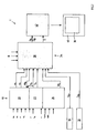
- the one shown in FIG Functionally schematic device 1 shown for monitoring the Functional and / or wear status of brake pads 2, 4 and the associated one Brake disc 6 of an electromechanical brake actuator 8 one Rail vehicle brake, as shown in Fig.1.
- the brake actuator 8 has a service brake unit and a memory brake unit with an energy store on.
- the service brake unit includes a brake force generator for application and / or releasing the brake, for example in the form of an electromotive Drive 10.
- the storage brake unit comprises an energy store, for example in the form of a spring accumulator 12, for storing and dispensing Energy to apply the brake as an operational emergency brake in the sense of a underlying security level in the event of failure of the service brake unit and / or as Parking or parking brake.
- a power converter 14 ensures implementation of the energy released by the braking force generator 10 and by the energy store 12 in a brake application movement and includes, for example, one of the electromotive Drive 10 driven brake spindle 16.
- the brake application movement is by putting on a right brake pad 2 and a left Brake pad 4 to the between the brake pads 2, 4 and assigned to them Brake disc 6 defined.
- the electric motor drive 10 is one Control and regulating electronics not shown for reasons of scale.
- Such a brake actuator 8 is described in detail in DE 199 45 702 A1, for example described, therefore we will not go into this here.
- the first wear calculation device 20 is designed such that it from the sliding speed V G , the temperature T B , the braking force F, the braking time t B , a brake pad surface A B , and material and temperature-specific parameters such as a correlation constant K B and exponent ⁇ , ⁇ and ⁇ determine the wear W B of at least one brake pad 2, 4 after the end of the braking period t B according to a wear model and according to the following calculation rule:
- the above-mentioned input variables are shown together with others in FIG. 2.
- the above-mentioned input variables are shown together with others in FIG. 2 on the left-hand side of the first functional level 18.
- the accumulated wear W B of both brake pads 2, 4 and the individual wear values W 1 and W 2 for the right brake pad 2 and left brake pad 4 are calculated using the equation (1) as the output variable of the first wear calculation device 20.
- the temperature device 22 likewise arranged in the first functional level 18, for the contactless measurement of the temperature T B of the friction surfaces of the brake pads 2, 4 during a braking operation is adequately described, for example, in the document DE 199 43 352 A1, the entire disclosure content of which is expressly referred to here.
- the friction surface temperature T B is derived there mathematically from a temperature model. This model determines the temperature T B of the friction surfaces of the brake pads 2, 4 as an output variable from the application forces, the application time, the material pairings, the route profile and other variables, which at the same time forms an input variable for the wear model according to equation (1).
- the temperature device 22 also determines the brake disc temperature T S.
- the temperatures T B , T S can also be measured by means of a non-contact sensor device, for example by means of a radiation pyrometer, which measures the thermal radiation of the friction surfaces.
- the speed n of the adjuster motor 28 can be used as a further input variable for the calculation, as indicated in FIG. 2, which is detected, for example, by means of a speed meter.
- an upper limit temperature T o which corresponds to a maximum permissible temperature of the brake pads 2, 4 or the brake disk 6, and a lower limit temperature T u , which corresponds to a minimum permissible temperature, below which unsatisfactory, act as further input variables of the first functional level 18 Frictional properties exist between the brake pads 2, 4 and the brake disc 6.
- the device 1 comprises a limit wear detection device 30 assigned to the right brake pad 2 and a limit wear detection device 32 assigned to the left brake pad 4, with each of which the detection of a maximum allowable degree of wear can be detected directly and a limit wear signal S Gr for the right brake pad 2 and separately of which, a limit wear signal S Gl for the left brake pad 4 can be generated.
- the limit wear detection devices 30, 32 preferably comprise conductor loops which are integrated into the brake linings 2, 4 and are arranged within electrical circuits and which, when the maximum permissible wear measure is reached, are provided for severing by means of the braking process that is currently taking place, the limit wear signals S Gl and S Gr are generated.
- Such a conductor loop is preferably assigned to each pair of brake pads 2, 4 of the rail vehicle brake, which comprises a plurality of brake actuators 8.
- Another second functional level, which is subordinate to the first functional level 18 34 of the device 1 includes one with the two limit wear detection devices 30, 32, the temperature device 22 and of the first and the second wear calculation device 20, 24 in signal connection standing evaluation device 36.
- the evaluation device 36 is also for the plausibility check and implausible results to generate an error signal S.
- the following are used as further input variables, as part of the first Functional level using certain sizes:
- specific parameters R are read into the evaluation device 36, such as, for example, brake lining material, brake disc diameter, friction radii, ambient temperatures, limit temperatures, etc.
- the temperatures T B of the brake pads 2, 4 and T S of the brake disc 6 on the one hand, and the total wear W G on the other hand are, for example, in a proportional relation to each other, as a relatively high Reib laketemperaturen T B and T S at a relatively large wear W G due. If the results deviate from this dependency, the plausibility check integrated in the evaluation device generates the error signal S, for example with relatively high calculated wear W G and relatively low friction surface temperatures T B and T S.
- the plausibility check is preferably carried out using the least squares method.
- the corresponding directly measured limit wear signal S Gl and S Gr which represents an additional and higher-level safety signal, has priority over a lining thickness W B of the brake linings 2, 4 calculated according to equation (6).
- the error signal S is also generated if, despite the presence of the limit wear signals S Gl and S Gr, the calculated wear value W B is too low.
- one-sided brake pad wear on the brake actuator 8 can be detected by comparing the wear W 1 of the right brake pad 2 and the wear W 2 of the left brake pad 4.
- the values and signals generated by the evaluation device 36 as output variables, such as the current lining thickness D B of the brake linings 2, 4 and the current thickness D S of the brake disk 6 and the error signal S possibly generated, are read into an electronic memory and displayed by means of a display device 38.
- the display device 38 is preferably connected to a stationary receiver 40, to which the output variables of the evaluation device 36 can be transmitted by a transmitter 42.
- At least part of the electronic components of the limit wear detection devices 30, 32, the temperature device 22, the first and the second wear calculation device 20, 24 and the evaluation device 36 are in the control electronics of the electromechanical Brake actuator 8 of the rail vehicle integrated.
Landscapes
- Engineering & Computer Science (AREA)
- Mechanical Engineering (AREA)
- General Engineering & Computer Science (AREA)
- Transportation (AREA)
- Braking Arrangements (AREA)
- Valves And Accessory Devices For Braking Systems (AREA)
Applications Claiming Priority (2)
| Application Number | Priority Date | Filing Date | Title |
|---|---|---|---|
| DE10233844 | 2002-07-25 | ||
| DE10233844A DE10233844B4 (de) | 2002-07-25 | 2002-07-25 | Vorrichtung und Verfahren zur Überwachung des Funktions- und/oder Verschleißzustandes von Bremsbelägen und Bremsscheiben einer Fahrzeugbremse |
Publications (3)
| Publication Number | Publication Date |
|---|---|
| EP1384638A2 true EP1384638A2 (fr) | 2004-01-28 |
| EP1384638A3 EP1384638A3 (fr) | 2005-11-16 |
| EP1384638B1 EP1384638B1 (fr) | 2009-09-23 |
Family
ID=29796566
Family Applications (1)
| Application Number | Title | Priority Date | Filing Date |
|---|---|---|---|
| EP03015521A Expired - Lifetime EP1384638B1 (fr) | 2002-07-25 | 2003-07-10 | Méthode et dispositif de surveillance de l'état d'usure et/ou de fonctionnement de garnitures et/ou disques de frein d'un véhicule |
Country Status (3)
| Country | Link |
|---|---|
| EP (1) | EP1384638B1 (fr) |
| AT (1) | ATE443642T1 (fr) |
| DE (2) | DE10233844B4 (fr) |
Cited By (20)
| Publication number | Priority date | Publication date | Assignee | Title |
|---|---|---|---|---|
| EP1640233A1 (fr) * | 2004-09-20 | 2006-03-29 | Faiveley Transport Remscheid GmbH | Appareil et procédé pour surveiller le fonctionnement d'un étrier de frein |
| FR2959717A1 (fr) * | 2010-05-05 | 2011-11-11 | Peugeot Citroen Automobiles Sa | Dispositif et procede pour la supervision de l'etat d'endommagement d'un disque de frein |
| WO2010057623A3 (fr) * | 2008-11-19 | 2012-02-02 | Eureka Navigation Solutions Ag | Dispositif et procédé pour un véhicule ferroviaire |
| EP2644466A1 (fr) * | 2012-03-28 | 2013-10-02 | Meritor Heavy Vehicle Braking Systems (UK) Limited | Procédé de determination du remanant de vie utilisable d'un component de frein |
| DE102014009681A1 (de) | 2013-08-02 | 2015-02-05 | Wabco Europe Bvba | Verfahren zum Überwachen einer Bremse sowie Bremse, die mit dem Verfahren überwacht wird |
| US9227615B2 (en) | 2012-03-28 | 2016-01-05 | Meritor Heavy Vehicle Braking Systems (Uk) Limited | Method of determining usable life of a brake component |
| EP3018380A3 (fr) * | 2014-10-06 | 2016-06-01 | Günther Zimmer | Frein a friction dote d'un dispositif de mesure de force |
| CN107806815A (zh) * | 2017-11-29 | 2018-03-16 | 四川海天仪表电器开发有限公司 | 装甲车辆制动器磨损量检测传感器 |
| EP3299234A1 (fr) * | 2016-07-29 | 2018-03-28 | Siemens AG Österreich | Paramétrage d'un modèle pour le pronostic d'usure de garnitures de frein |
| CN107893828A (zh) * | 2017-09-26 | 2018-04-10 | 中国铁路通信信号上海工程局集团有限公司 | 动车组刹车片磨损情况实时在线监测系统 |
| RU2668784C1 (ru) * | 2015-01-29 | 2018-10-02 | Сименс Аг Эстеррайх | Прогнозирование износа в тормозных накладках |
| WO2019206577A1 (fr) * | 2018-04-25 | 2019-10-31 | Knorr-Bremse Systeme für Nutzfahrzeuge GmbH | Procédé servant à afficher un changement de garniture de frein imminent d'un frein de véhicule |
| WO2020127210A1 (fr) * | 2018-12-17 | 2020-06-25 | Greenbrakes Gmbh | Système de freinage |
| CN112313127A (zh) * | 2018-06-22 | 2021-02-02 | 罗伯特·博世有限公司 | 用于操控车辆中的机电的制动装置的方法 |
| CN112533807A (zh) * | 2018-08-22 | 2021-03-19 | 威伯科有限公司 | 电子制动系统 |
| CN114370471A (zh) * | 2022-01-05 | 2022-04-19 | 东风柳州汽车有限公司 | 刹车片磨损提醒方法、装置、设备及存储介质 |
| CN114458708A (zh) * | 2021-08-25 | 2022-05-10 | 苏州麦哲轮汽车电子科技有限公司 | 一种汽车制动钳温度传感控制系统及控制方法 |
| CN115163708A (zh) * | 2022-06-21 | 2022-10-11 | 东风柳州汽车有限公司 | 一种制动盘温度的实时检测方法和装置 |
| CN115557382A (zh) * | 2022-09-15 | 2023-01-03 | 中国矿业大学 | 一种单轨吊机车多点协同制动控制方法 |
| WO2024033137A1 (fr) * | 2022-08-09 | 2024-02-15 | Knorr-Bremse Systeme für Schienenfahrzeuge GmbH | Étrier de frein compact à actionneur électromécanique, entraînement d'arbre à cames et dispositif de réglage mécanique, et procédé de fonctionnement d'un tel étrier de frein |
Families Citing this family (6)
| Publication number | Priority date | Publication date | Assignee | Title |
|---|---|---|---|---|
| DE102018117127A1 (de) | 2018-07-16 | 2020-01-16 | RailWatch GmbH & Co. KG | Verfahren zum Überwachen einer Bremsanlage eines Schienenfahrzeugs |
| DE102020107835A1 (de) | 2020-03-23 | 2021-09-23 | Knorr-Bremse Systeme für Schienenfahrzeuge GmbH | Betriebsbremszylinder, insbesondere einer Klotzbremse, mit Bremszustandserfassung und Verfahren zum Erfassen eines Bremszustands eines Betriebsbremszylinders, insbesondere einer Klotzbremse |
| IT202100005636A1 (it) * | 2021-03-10 | 2022-09-10 | Itt Italia Srl | Metodo di stima dell'usura di un elemento del freno di un veicolo |
| CN119032030A (zh) * | 2022-03-25 | 2024-11-26 | 意大利Itt有限责任公司 | 针对车辆制动元件中的磨损的估计方法 |
| EP4574598A1 (fr) * | 2023-12-21 | 2025-06-25 | Wabtec Faiveley Nordic AB | Système et procédé de commande pour véhicule ferroviaire pour lutter contre les dommages des composants dus au freinage |
| FR3160223A1 (fr) * | 2024-03-12 | 2025-09-19 | Safran | Procédé et système de détermination de l’usure d’un frein |
Citations (1)
| Publication number | Priority date | Publication date | Assignee | Title |
|---|---|---|---|---|
| DE19945702A1 (de) | 1999-09-23 | 2001-04-19 | Knorr Bremse Systeme | Zuspannvorrichtung für eine Fahrzeugbremse |
Family Cites Families (6)
| Publication number | Priority date | Publication date | Assignee | Title |
|---|---|---|---|---|
| US5201834A (en) * | 1989-04-05 | 1993-04-13 | Inventio Ag | Method for the testing and monitoring of brakes in rail vehicles |
| DE4212387B4 (de) * | 1992-04-13 | 2004-08-26 | Knorr-Bremse Ag | Belagverschleißdetektor für eine druckluftbetätigte Scheibenbremse |
| DE4230831B4 (de) * | 1992-09-15 | 2004-02-26 | Knorr-Bremse Systeme für Nutzfahrzeuge GmbH | Belagverschleißdetektor für eine Scheibenbremse |
| GB9411477D0 (en) * | 1994-06-08 | 1994-07-27 | Lucas Ind Plc | Brake lining wear sensing system |
| DE19943352A1 (de) * | 1999-09-10 | 2001-04-05 | Knorr Bremse Systeme | Vorrichtung und Verfahren zum Bestimmen der Temperatur an einem Fahrzeug vorgesehenen Bremselementen |
| DE10029238B9 (de) * | 2000-06-14 | 2006-05-24 | Bayerische Motoren Werke Ag | Verfahren zur Überwachung der Stärke der Bremsbeläge einer Fahrzeug-Bremsanlage |
-
2002
- 2002-07-25 DE DE10233844A patent/DE10233844B4/de not_active Expired - Fee Related
-
2003
- 2003-07-10 AT AT03015521T patent/ATE443642T1/de not_active IP Right Cessation
- 2003-07-10 DE DE50311936T patent/DE50311936D1/de not_active Expired - Lifetime
- 2003-07-10 EP EP03015521A patent/EP1384638B1/fr not_active Expired - Lifetime
Patent Citations (1)
| Publication number | Priority date | Publication date | Assignee | Title |
|---|---|---|---|---|
| DE19945702A1 (de) | 1999-09-23 | 2001-04-19 | Knorr Bremse Systeme | Zuspannvorrichtung für eine Fahrzeugbremse |
Cited By (32)
| Publication number | Priority date | Publication date | Assignee | Title |
|---|---|---|---|---|
| EP1640233A1 (fr) * | 2004-09-20 | 2006-03-29 | Faiveley Transport Remscheid GmbH | Appareil et procédé pour surveiller le fonctionnement d'un étrier de frein |
| WO2010057623A3 (fr) * | 2008-11-19 | 2012-02-02 | Eureka Navigation Solutions Ag | Dispositif et procédé pour un véhicule ferroviaire |
| US9211879B2 (en) | 2008-11-19 | 2015-12-15 | Eureka Navigation Solutions Ag | Device and method for a rail vehicle |
| FR2959717A1 (fr) * | 2010-05-05 | 2011-11-11 | Peugeot Citroen Automobiles Sa | Dispositif et procede pour la supervision de l'etat d'endommagement d'un disque de frein |
| EP2644466A1 (fr) * | 2012-03-28 | 2013-10-02 | Meritor Heavy Vehicle Braking Systems (UK) Limited | Procédé de determination du remanant de vie utilisable d'un component de frein |
| US9227615B2 (en) | 2012-03-28 | 2016-01-05 | Meritor Heavy Vehicle Braking Systems (Uk) Limited | Method of determining usable life of a brake component |
| DE102014009681A1 (de) | 2013-08-02 | 2015-02-05 | Wabco Europe Bvba | Verfahren zum Überwachen einer Bremse sowie Bremse, die mit dem Verfahren überwacht wird |
| EP3018380A3 (fr) * | 2014-10-06 | 2016-06-01 | Günther Zimmer | Frein a friction dote d'un dispositif de mesure de force |
| RU2668784C1 (ru) * | 2015-01-29 | 2018-10-02 | Сименс Аг Эстеррайх | Прогнозирование износа в тормозных накладках |
| US10919513B2 (en) | 2015-01-29 | 2021-02-16 | Siemens Mobility Austria Gmbh | Device and method for forecasting wear in brake linings |
| AT519086A4 (de) * | 2016-07-29 | 2018-04-15 | Siemens Ag Oesterreich | Verfahren zur Bestimmung der Abnutzung von Bremsbelägen von Fahrzeugen |
| AT519086B1 (de) * | 2016-07-29 | 2018-04-15 | Siemens Ag Oesterreich | Verfahren zur Bestimmung der Abnutzung von Bremsbelägen von Fahrzeugen |
| EP3299234A1 (fr) * | 2016-07-29 | 2018-03-28 | Siemens AG Österreich | Paramétrage d'un modèle pour le pronostic d'usure de garnitures de frein |
| CN107893828B (zh) * | 2017-09-26 | 2023-10-13 | 中国铁路通信信号上海工程局集团有限公司 | 动车组刹车片磨损情况实时在线监测系统 |
| CN107893828A (zh) * | 2017-09-26 | 2018-04-10 | 中国铁路通信信号上海工程局集团有限公司 | 动车组刹车片磨损情况实时在线监测系统 |
| CN107806815B (zh) * | 2017-11-29 | 2024-04-02 | 四川海天仪表电器开发有限公司 | 装甲车辆制动器磨损量检测传感器 |
| CN107806815A (zh) * | 2017-11-29 | 2018-03-16 | 四川海天仪表电器开发有限公司 | 装甲车辆制动器磨损量检测传感器 |
| WO2019206577A1 (fr) * | 2018-04-25 | 2019-10-31 | Knorr-Bremse Systeme für Nutzfahrzeuge GmbH | Procédé servant à afficher un changement de garniture de frein imminent d'un frein de véhicule |
| CN112313127A (zh) * | 2018-06-22 | 2021-02-02 | 罗伯特·博世有限公司 | 用于操控车辆中的机电的制动装置的方法 |
| CN112313127B (zh) * | 2018-06-22 | 2023-03-24 | 罗伯特·博世有限公司 | 用于操控车辆中的机电的制动装置的方法 |
| CN112533807B (zh) * | 2018-08-22 | 2023-02-17 | 威伯科有限公司 | 电子制动系统 |
| CN112533807A (zh) * | 2018-08-22 | 2021-03-19 | 威伯科有限公司 | 电子制动系统 |
| WO2020127210A1 (fr) * | 2018-12-17 | 2020-06-25 | Greenbrakes Gmbh | Système de freinage |
| US12084025B2 (en) | 2018-12-17 | 2024-09-10 | Greenbrakes Gmbh | Brake system |
| CN114458708A (zh) * | 2021-08-25 | 2022-05-10 | 苏州麦哲轮汽车电子科技有限公司 | 一种汽车制动钳温度传感控制系统及控制方法 |
| CN114458708B (zh) * | 2021-08-25 | 2024-03-26 | 苏州麦哲轮汽车电子科技有限公司 | 一种汽车制动钳温度传感控制系统及控制方法 |
| CN114370471B (zh) * | 2022-01-05 | 2023-09-01 | 东风柳州汽车有限公司 | 刹车片磨损提醒方法、装置、设备及存储介质 |
| CN114370471A (zh) * | 2022-01-05 | 2022-04-19 | 东风柳州汽车有限公司 | 刹车片磨损提醒方法、装置、设备及存储介质 |
| CN115163708A (zh) * | 2022-06-21 | 2022-10-11 | 东风柳州汽车有限公司 | 一种制动盘温度的实时检测方法和装置 |
| CN115163708B (zh) * | 2022-06-21 | 2023-07-25 | 东风柳州汽车有限公司 | 一种制动盘温度的实时检测方法和装置 |
| WO2024033137A1 (fr) * | 2022-08-09 | 2024-02-15 | Knorr-Bremse Systeme für Schienenfahrzeuge GmbH | Étrier de frein compact à actionneur électromécanique, entraînement d'arbre à cames et dispositif de réglage mécanique, et procédé de fonctionnement d'un tel étrier de frein |
| CN115557382A (zh) * | 2022-09-15 | 2023-01-03 | 中国矿业大学 | 一种单轨吊机车多点协同制动控制方法 |
Also Published As
| Publication number | Publication date |
|---|---|
| EP1384638B1 (fr) | 2009-09-23 |
| DE10233844A1 (de) | 2004-02-12 |
| ATE443642T1 (de) | 2009-10-15 |
| DE10233844B4 (de) | 2007-06-14 |
| EP1384638A3 (fr) | 2005-11-16 |
| DE50311936D1 (de) | 2009-11-05 |
Similar Documents
| Publication | Publication Date | Title |
|---|---|---|
| DE10233844B4 (de) | Vorrichtung und Verfahren zur Überwachung des Funktions- und/oder Verschleißzustandes von Bremsbelägen und Bremsscheiben einer Fahrzeugbremse | |
| DE102016115275B4 (de) | Diagnose- und Anzeigeverfahren zum Erlangen einer Bremsscheibentemperatur für eine Bremsdiagnoseeinrichtung einer Bremseinrichtung eines Fahrzeugs | |
| DE102019114543B4 (de) | Verfahren zum Ermitteln einer Restlebensdauer einer Bremskomponente | |
| EP2475564B1 (fr) | Procédé permettant de prédire la température d'un roulement d'une roue d'un véhicule | |
| EP3665048B1 (fr) | Procédé et dispositif pour déterminer des modifications dans le comportement de dynamique longitudinale d'un véhicule ferroviaire | |
| DE10259529B4 (de) | Verfahren zur Ermittlung eines Bremsenzustands | |
| DE69810483T2 (de) | Verfahren und einrichtung zur erkennung einer falsch eingestellten spielnachstellung für bremsen | |
| DE102019134292A1 (de) | Intelligente zustandsüberwachung des bremssystems | |
| DE102018117082A1 (de) | Bremsrotorprognose | |
| DE102018124901A1 (de) | Bremsbelagverschleiss-Schätzung | |
| DE102017002148B4 (de) | Verfahren und System zur Vorhersage der Restlebensdauer einer Bremsscheibe in einem Scheibenbremssystem eines Fahrzeugs | |
| DE102011113069B4 (de) | Steuereinrichtung für ein Schienenfahrzeug sowie Verfahren zum Bestimmen eines Kraftschlusswertes für ein Schienenfahrzeug | |
| EP2996913A2 (fr) | Procédé et dispositif pour déterminer un couple de freinage dans un système de freinage pour un véhicule ferroviaire | |
| DE19943352A1 (de) | Vorrichtung und Verfahren zum Bestimmen der Temperatur an einem Fahrzeug vorgesehenen Bremselementen | |
| AT516803A1 (de) | Verschleißprognose bei Bremsbelägen | |
| EP3448728B1 (fr) | Dispositif et procédé pour optimiser l'utilisation de l'adhérence entre la roue et le rail | |
| EP0961723B1 (fr) | Procede et systeme de reglage pour l'application de forces d'actionnement definies | |
| DE102016109497A1 (de) | Verfahren und Vorrichtung zum Ermitteln des Verschleißzustandes von Komponenten eines Schienenfahrzeugs | |
| AT519086A4 (de) | Verfahren zur Bestimmung der Abnutzung von Bremsbelägen von Fahrzeugen | |
| DE102009011986B4 (de) | Verfahren zum Ermitteln des Verschleißzustands einer Reibbremse oder -kupplung und eine Reibbremse oder -kupplung | |
| DE102016220415A1 (de) | Schätzverfahren für den Reibwert eines hydraulischen Bremssystems | |
| DE102016215725A1 (de) | Verfahren zur prädiktiven Verschleißerkennung in Kraftfahrzeugbremsanlagen | |
| WO2013024018A2 (fr) | Système de frein électromagnétique à patin pour un véhicule ferroviaire | |
| DE10208961A1 (de) | Verschleißerkennung bei Kraftfahrzeugen | |
| DE102013201594A1 (de) | Verfahren und Vorrichtung zur Genauigkeitsbewertung von Geschwindigkeitswerten, insbesondere eines Schienenfahrzeuges |
Legal Events
| Date | Code | Title | Description |
|---|---|---|---|
| PUAI | Public reference made under article 153(3) epc to a published international application that has entered the european phase |
Free format text: ORIGINAL CODE: 0009012 |
|
| AK | Designated contracting states |
Kind code of ref document: A2 Designated state(s): AT BE BG CH CY CZ DE DK EE ES FI FR GB GR HU IE IT LI LU MC NL PT RO SE SI SK TR |
|
| AX | Request for extension of the european patent |
Extension state: AL LT LV MK |
|
| PUAL | Search report despatched |
Free format text: ORIGINAL CODE: 0009013 |
|
| AK | Designated contracting states |
Kind code of ref document: A3 Designated state(s): AT BE BG CH CY CZ DE DK EE ES FI FR GB GR HU IE IT LI LU MC NL PT RO SE SI SK TR |
|
| AX | Request for extension of the european patent |
Extension state: AL LT LV MK |
|
| RIC1 | Information provided on ipc code assigned before grant |
Ipc: 7B 61H 5/00 B Ipc: 7F 16D 66/02 B Ipc: 7B 60T 17/22 A |
|
| 17P | Request for examination filed |
Effective date: 20060516 |
|
| AKX | Designation fees paid |
Designated state(s): AT BE BG CH CY CZ DE DK EE ES FI FR GB GR HU IE IT LI LU MC NL PT RO SE SI SK TR |
|
| 17Q | First examination report despatched |
Effective date: 20060626 |
|
| GRAP | Despatch of communication of intention to grant a patent |
Free format text: ORIGINAL CODE: EPIDOSNIGR1 |
|
| GRAS | Grant fee paid |
Free format text: ORIGINAL CODE: EPIDOSNIGR3 |
|
| GRAA | (expected) grant |
Free format text: ORIGINAL CODE: 0009210 |
|
| RIN1 | Information on inventor provided before grant (corrected) |
Inventor name: WAGNER, THOMAS |
|
| AK | Designated contracting states |
Kind code of ref document: B1 Designated state(s): AT BE BG CH CY CZ DE DK EE ES FI FR GB GR HU IE IT LI LU MC NL PT RO SE SI SK TR |
|
| REG | Reference to a national code |
Ref country code: GB Ref legal event code: FG4D Free format text: NOT ENGLISH |
|
| REG | Reference to a national code |
Ref country code: CH Ref legal event code: EP |
|
| REG | Reference to a national code |
Ref country code: IE Ref legal event code: FG4D |
|
| REF | Corresponds to: |
Ref document number: 50311936 Country of ref document: DE Date of ref document: 20091105 Kind code of ref document: P |
|
| PG25 | Lapsed in a contracting state [announced via postgrant information from national office to epo] |
Ref country code: FI Free format text: LAPSE BECAUSE OF FAILURE TO SUBMIT A TRANSLATION OF THE DESCRIPTION OR TO PAY THE FEE WITHIN THE PRESCRIBED TIME-LIMIT Effective date: 20090923 Ref country code: SE Free format text: LAPSE BECAUSE OF FAILURE TO SUBMIT A TRANSLATION OF THE DESCRIPTION OR TO PAY THE FEE WITHIN THE PRESCRIBED TIME-LIMIT Effective date: 20090923 |
|
| PG25 | Lapsed in a contracting state [announced via postgrant information from national office to epo] |
Ref country code: SI Free format text: LAPSE BECAUSE OF FAILURE TO SUBMIT A TRANSLATION OF THE DESCRIPTION OR TO PAY THE FEE WITHIN THE PRESCRIBED TIME-LIMIT Effective date: 20090923 |
|
| NLV1 | Nl: lapsed or annulled due to failure to fulfill the requirements of art. 29p and 29m of the patents act | ||
| PG25 | Lapsed in a contracting state [announced via postgrant information from national office to epo] |
Ref country code: CY Free format text: LAPSE BECAUSE OF FAILURE TO SUBMIT A TRANSLATION OF THE DESCRIPTION OR TO PAY THE FEE WITHIN THE PRESCRIBED TIME-LIMIT Effective date: 20090923 |
|
| REG | Reference to a national code |
Ref country code: IE Ref legal event code: FD4D |
|
| PG25 | Lapsed in a contracting state [announced via postgrant information from national office to epo] |
Ref country code: PT Free format text: LAPSE BECAUSE OF FAILURE TO SUBMIT A TRANSLATION OF THE DESCRIPTION OR TO PAY THE FEE WITHIN THE PRESCRIBED TIME-LIMIT Effective date: 20100125 Ref country code: IE Free format text: LAPSE BECAUSE OF FAILURE TO SUBMIT A TRANSLATION OF THE DESCRIPTION OR TO PAY THE FEE WITHIN THE PRESCRIBED TIME-LIMIT Effective date: 20090923 Ref country code: CZ Free format text: LAPSE BECAUSE OF FAILURE TO SUBMIT A TRANSLATION OF THE DESCRIPTION OR TO PAY THE FEE WITHIN THE PRESCRIBED TIME-LIMIT Effective date: 20090923 Ref country code: ES Free format text: LAPSE BECAUSE OF FAILURE TO SUBMIT A TRANSLATION OF THE DESCRIPTION OR TO PAY THE FEE WITHIN THE PRESCRIBED TIME-LIMIT Effective date: 20100103 Ref country code: EE Free format text: LAPSE BECAUSE OF FAILURE TO SUBMIT A TRANSLATION OF THE DESCRIPTION OR TO PAY THE FEE WITHIN THE PRESCRIBED TIME-LIMIT Effective date: 20090923 Ref country code: RO Free format text: LAPSE BECAUSE OF FAILURE TO SUBMIT A TRANSLATION OF THE DESCRIPTION OR TO PAY THE FEE WITHIN THE PRESCRIBED TIME-LIMIT Effective date: 20090923 |
|
| PG25 | Lapsed in a contracting state [announced via postgrant information from national office to epo] |
Ref country code: SK Free format text: LAPSE BECAUSE OF FAILURE TO SUBMIT A TRANSLATION OF THE DESCRIPTION OR TO PAY THE FEE WITHIN THE PRESCRIBED TIME-LIMIT Effective date: 20090923 |
|
| PG25 | Lapsed in a contracting state [announced via postgrant information from national office to epo] |
Ref country code: DK Free format text: LAPSE BECAUSE OF FAILURE TO SUBMIT A TRANSLATION OF THE DESCRIPTION OR TO PAY THE FEE WITHIN THE PRESCRIBED TIME-LIMIT Effective date: 20090923 Ref country code: NL Free format text: LAPSE BECAUSE OF FAILURE TO SUBMIT A TRANSLATION OF THE DESCRIPTION OR TO PAY THE FEE WITHIN THE PRESCRIBED TIME-LIMIT Effective date: 20090923 |
|
| PLBE | No opposition filed within time limit |
Free format text: ORIGINAL CODE: 0009261 |
|
| STAA | Information on the status of an ep patent application or granted ep patent |
Free format text: STATUS: NO OPPOSITION FILED WITHIN TIME LIMIT |
|
| 26N | No opposition filed |
Effective date: 20100624 |
|
| PG25 | Lapsed in a contracting state [announced via postgrant information from national office to epo] |
Ref country code: GR Free format text: LAPSE BECAUSE OF FAILURE TO SUBMIT A TRANSLATION OF THE DESCRIPTION OR TO PAY THE FEE WITHIN THE PRESCRIBED TIME-LIMIT Effective date: 20091224 |
|
| BERE | Be: lapsed |
Owner name: KNORR-BREMSE SYSTEME FUR SCHIENENFAHRZEUGE G.M.B. Effective date: 20100731 |
|
| PG25 | Lapsed in a contracting state [announced via postgrant information from national office to epo] |
Ref country code: MC Free format text: LAPSE BECAUSE OF NON-PAYMENT OF DUE FEES Effective date: 20100731 |
|
| REG | Reference to a national code |
Ref country code: CH Ref legal event code: PL |
|
| GBPC | Gb: european patent ceased through non-payment of renewal fee |
Effective date: 20100710 |
|
| PG25 | Lapsed in a contracting state [announced via postgrant information from national office to epo] |
Ref country code: IT Free format text: LAPSE BECAUSE OF FAILURE TO SUBMIT A TRANSLATION OF THE DESCRIPTION OR TO PAY THE FEE WITHIN THE PRESCRIBED TIME-LIMIT Effective date: 20090923 |
|
| REG | Reference to a national code |
Ref country code: FR Ref legal event code: ST Effective date: 20110331 |
|
| PG25 | Lapsed in a contracting state [announced via postgrant information from national office to epo] |
Ref country code: LI Free format text: LAPSE BECAUSE OF NON-PAYMENT OF DUE FEES Effective date: 20100731 Ref country code: CH Free format text: LAPSE BECAUSE OF NON-PAYMENT OF DUE FEES Effective date: 20100731 |
|
| PG25 | Lapsed in a contracting state [announced via postgrant information from national office to epo] |
Ref country code: FR Free format text: LAPSE BECAUSE OF NON-PAYMENT OF DUE FEES Effective date: 20100802 |
|
| PG25 | Lapsed in a contracting state [announced via postgrant information from national office to epo] |
Ref country code: BE Free format text: LAPSE BECAUSE OF NON-PAYMENT OF DUE FEES Effective date: 20100731 |
|
| PG25 | Lapsed in a contracting state [announced via postgrant information from national office to epo] |
Ref country code: GB Free format text: LAPSE BECAUSE OF NON-PAYMENT OF DUE FEES Effective date: 20100710 |
|
| PG25 | Lapsed in a contracting state [announced via postgrant information from national office to epo] |
Ref country code: AT Free format text: LAPSE BECAUSE OF NON-PAYMENT OF DUE FEES Effective date: 20100710 |
|
| PG25 | Lapsed in a contracting state [announced via postgrant information from national office to epo] |
Ref country code: LU Free format text: LAPSE BECAUSE OF NON-PAYMENT OF DUE FEES Effective date: 20100710 Ref country code: HU Free format text: LAPSE BECAUSE OF FAILURE TO SUBMIT A TRANSLATION OF THE DESCRIPTION OR TO PAY THE FEE WITHIN THE PRESCRIBED TIME-LIMIT Effective date: 20100324 Ref country code: BG Free format text: LAPSE BECAUSE OF FAILURE TO SUBMIT A TRANSLATION OF THE DESCRIPTION OR TO PAY THE FEE WITHIN THE PRESCRIBED TIME-LIMIT Effective date: 20090923 |
|
| PG25 | Lapsed in a contracting state [announced via postgrant information from national office to epo] |
Ref country code: TR Free format text: LAPSE BECAUSE OF FAILURE TO SUBMIT A TRANSLATION OF THE DESCRIPTION OR TO PAY THE FEE WITHIN THE PRESCRIBED TIME-LIMIT Effective date: 20090923 |
|
| PGFP | Annual fee paid to national office [announced via postgrant information from national office to epo] |
Ref country code: DE Payment date: 20150722 Year of fee payment: 13 |
|
| REG | Reference to a national code |
Ref country code: DE Ref legal event code: R119 Ref document number: 50311936 Country of ref document: DE |
|
| PG25 | Lapsed in a contracting state [announced via postgrant information from national office to epo] |
Ref country code: DE Free format text: LAPSE BECAUSE OF NON-PAYMENT OF DUE FEES Effective date: 20170201 |