EP1384694A1 - Umlenktopf für den Einbau in pneumatische Förderanlagen - Google Patents
Umlenktopf für den Einbau in pneumatische Förderanlagen Download PDFInfo
- Publication number
- EP1384694A1 EP1384694A1 EP03010775A EP03010775A EP1384694A1 EP 1384694 A1 EP1384694 A1 EP 1384694A1 EP 03010775 A EP03010775 A EP 03010775A EP 03010775 A EP03010775 A EP 03010775A EP 1384694 A1 EP1384694 A1 EP 1384694A1
- Authority
- EP
- European Patent Office
- Prior art keywords
- deflection
- ring
- wear
- pot according
- wear ring
- Prior art date
- Legal status (The legal status is an assumption and is not a legal conclusion. Google has not performed a legal analysis and makes no representation as to the accuracy of the status listed.)
- Granted
Links
Images

Classifications
-
- F—MECHANICAL ENGINEERING; LIGHTING; HEATING; WEAPONS; BLASTING
- F16—ENGINEERING ELEMENTS AND UNITS; GENERAL MEASURES FOR PRODUCING AND MAINTAINING EFFECTIVE FUNCTIONING OF MACHINES OR INSTALLATIONS; THERMAL INSULATION IN GENERAL
- F16L—PIPES; JOINTS OR FITTINGS FOR PIPES; SUPPORTS FOR PIPES, CABLES OR PROTECTIVE TUBING; MEANS FOR THERMAL INSULATION IN GENERAL
- F16L43/00—Bends; Siphons
-
- B—PERFORMING OPERATIONS; TRANSPORTING
- B65—CONVEYING; PACKING; STORING; HANDLING THIN OR FILAMENTARY MATERIAL
- B65G—TRANSPORT OR STORAGE DEVICES, e.g. CONVEYORS FOR LOADING OR TIPPING, SHOP CONVEYOR SYSTEMS OR PNEUMATIC TUBE CONVEYORS
- B65G53/00—Conveying materials in bulk through troughs, pipes or tubes by floating the materials or by flow of gas, liquid or foam
- B65G53/34—Details
- B65G53/52—Adaptations of pipes or tubes
- B65G53/523—Wear protection
Definitions
- the invention relates to a deflection pot for installation in pneumatic conveyors the preamble of claim 1.
- One area of application of the deflection pot according to the invention is the installation in pneumatic Conveyor systems for building material silos.
- the deflection cup according to the invention is not limited to this application, but basically for any type of pneumatic Conveyors can be used.
- the material is fed into the Blown in silos.
- the silo lines are sometimes deflected several times by 90 °.
- the deflection pots used are caused by one-sided loading and swirling an increased wear that continues in the downstream pipes. This is especially the case with abrasive materials such as quartz or sand.
- the problem area is the outlet of the deflection cup. The hole is widened, and the adjoining outlet pipe also wears out. The problems then arise when replacing the outlet pipe.
- the new pipes have an exactly circular and accurate diameter. Now this circular tube is attached to the widened oval Flanged outlet bore of the deflection cup, so a baffle edge is created on the new Outlet pipe, along which the material runs.
- the object of the invention is to create a deflection cup of the type specified at the outset with a longer service life.
- Deflection cup consists of one where there is increased wear in the pot outlet easy to replace wear ring. This results in an essential one Extended service life of the deflection cup and the following pipes.
- You can existing deflection pots are retrofitted in the manner according to the invention, by mechanically machining the outlet bore of the deflection pot such that a easy to change wear ring can be used. Is this wear ring or the subsequent pipe is worn out, they can easily be replaced so that you get an almost today's deflection pot again.
- the formation of the wear ring as a hollow cylinder according to the training claim 2 shows a possibility of simply providing such a wear ring, Because a hollow cylinder is technically easy to manufacture and is therefore inexpensive Product.
- the development according to claim 3 has the advantage that such a ring recess easy to manufacture, especially in the case of existing deflection pots an upgrade.
- the ring recess extends to the end face of the outlet of the Umlenktopfes. This means that the wear ring, especially the hollow cylinder, is simple can be inserted from the outside into the ring recess, the end face of the wear ring is flush with the end face of the deflection cup.
- this centering device can be a Act centering ring.
- the use of a centering ring makes it technically simple Possibility to implement the centering device.
- the centering ring is preferably in annular grooves arranged. Such an annular groove can easily be in the end face of the outlet be milled. Since the outlet pipe also has such an annular groove precise centering achieved by using the centering ring in the two ring grooves. A baffle due to centering errors is thus technically simple Avoided way.
- the training suggests a technical implementation of the wear monitoring device according to claim 9.
- the basic idea of this wear monitoring lies in one Pressure monitoring, which is carried out by means of a leakage indicator can.
- the wear of the wear ring can be monitored by using this device become.
- a cavity is formed in the wear ring. In the built-in Condition of the wear ring, this cavity is led to the outside through a hole.
- a corresponding device can be connected here.
- the cavity is with Overpressure (nitrogen or compressed air) is applied. Is the wear ring in the area of If the cavity is worn, the pressure in it drops and gives an alarm. this is the Time to replace the wear ring with a new one. Because of the engagement one distributor, a pressure control device can be used for several deflection pots.
- the cavity is preferably by an external circumference Ring groove formed in the wear ring.
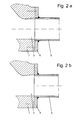
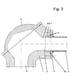
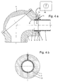
- Fig. 1 and Figs. 2a and 2b show a deflection pot according to the prior art (for Clarification of the problem). 3 and 4a and 4b show two embodiments of the deflection pot according to the invention.
- the deflection pot 1 shown in FIG. 1 in the form of a deflection bend has an inlet 2 as well as an outlet 3.
- a cover 4 is provided in the outer arch area.
- FIG. 2a shows the deflection pot 1 with a flanged outlet pipe 5. For this there is an annular one Flange 6 provided. While the original inner diameter of the outlet pipe 5 is shown in dashed lines, the state of the deflection pot 1 and the outlet pipe 5 shown after wear. At some point the state is reached in which the outlet pipe 5 breaks through.
- the deflection cup 1 as shown in FIG. 3, has in the area of Outlet 3 of the deflector 1 on a hollow cylindrical wear ring 7. This is inserted into a corresponding ring recess 8 in the outlet 3 of the deflection cup 1.
- the Inner wall 9 of the deflection pot 1 goes continuously into the inner wall of the wear ring 7 over. This also applies to the transition to the outlet pipe 5.
- a centering ring 10 is provided for centering the outlet pipe 5 on the deflection cup 1. To this purpose is in the end wall of the deflection cup 1 and in the end wall of the flange 6 each have an annular groove 11.
- FIGS. 4a and 4b The modified embodiment of FIGS. 4a and 4b is based on the same basic principle out.
- the extension consists of wear monitoring.
- the wear ring 7 with a cavity 12 in the form of an outer circumference Provide ring groove.
- a seal 13 is provided, so that the cavity 12 is pressure-tight is completed.
- a connection 14 opens into the cavity 12 and a pressure monitoring device 15 is connected.
- an excess pressure is generated in the cavity 12 Generates nitrogen or compressed air.
- the pressure is measured and monitored. Once the Wear in the wear ring 7 has become so great that the cavity 12 leaks the overpressure gas escapes. A pressure drop can be determined, which detects and is displayed. The wear ring 7 and the outlet pipe 5 can then subsequently due to reaching the wear limit.
Landscapes
- Engineering & Computer Science (AREA)
- General Engineering & Computer Science (AREA)
- Mechanical Engineering (AREA)
- Air Transport Of Granular Materials (AREA)
- Branching, Merging, And Special Transfer Between Conveyors (AREA)
- Filling Or Emptying Of Bunkers, Hoppers, And Tanks (AREA)
Abstract
Description
- Fig. 1
- einen Längsschnitt durch den Umlenktopf im Ursprungszustand;
- Fig. 2a
- einen Längsschnitt durch den Umlenktopf der Fig. 1 mit angeflanschtem Auslaufrohr im Zustand des Verschleißes;
- Fig. 2b
- die Anordnung in Fig. 2a nach dem Ersetzen des verschlissenen Auslaufrohres durch ein neues Auslaufrohr;
- Fig. 3
- einen Längsschnitt durch den erfindungsgemäßen Umlenktopf in einer ersten Ausführungsform;
- Fig. 4a
- eine zweite Ausführungsform mit zusätzlicher Verschleißüberwachung;
- Fig. 4b
- einen Querschnitt durch den Umlenktopf im Bereich der Verschleißüberwachung in Fig. 4a.
- 1
- Umlenktopf
- 2
- Einlass
- 3
- Auslass
- 4
- Deckel
- 5
- Auslaufrohr
- 6
- Flansch
- 7
- Verschleißring
- 8
- Ringausnehmung
- 9
- Innenwandung
- 10
- Zentrierung
- 11
- Ringnut
- 12
- Hohlraum
- 13
- Dichtung
- 14
- Anschluß
- 15
- Drucküberwachungseinrichtung
Claims (10)
- Umlenktopf (1) für den Einbau in pneumatische Förderanlagen, mit einem Einlass (2) zum Anschließen eines Zulaufrohres sowie mit einem Auslass (3) zum Anschließen eines Auslaufrohres (5) mittels eines Flansches (6),
dadurch gekennzeichnet, dass die Innenwandung (9) des Auslasses (3) des Umlenktopfes (1) mit einem auswechselbaren Verschleißring (7) versehen ist. - Umlenktopf nach dem vorhergehenden Anspruch,
dadurch gekennzeichnet, dass der Verschleißring (7) ein Hohlzylinder ist. - Umlenktopf nach einem der vorhergehenden Ansprüche,
dadurch gekennzeichnet, dass der Verschleißring (7) in einer im Auslass (3) ausgebildeten, korrespondierenden Ringausnehmung (8) angeordnet ist. - Umlenktopf nach einem der vorhergehenden Ansprüche,
dadurch gekennzeichnet, dass der Verschleißring (7) bündig in der Innenmantelfläche des Umlenktopfes (1) liegt. - Umlenktopf nach einem der vorhergehenden Ansprüche,
dadurch gekennzeichnet, dass in der Kontaktfläche zwischen der Stirnseite des Umlenktopfes (1) einerseits und der Stirnseite des Flansches (6) des Auslaufrohres (5) andererseits eine Zentriereinrichtung vorgesehen ist. - Umlenktopf nach Anspruch 5,
dadurch gekennzeichnet, dass die Zentriereinrichtung einen Zentrierring (10) aufweist. - Umlenktopf nach Anspruch 6,
dadurch gekennzeichnet, dass der Zentrierring (10) in Ringnuten (11) in den beiden Stirnseiten angeordnet ist. - Umlenktopf nach einem der vorhergehenden Ansprüche,
dadurch gekennzeichnet, dass dem Verschleißring (7) eine Verschleißüberwachungseinrichtung zugeordnet ist. - Umlenktopf nach Anspruch 8,
dadurch gekennzeichnet, dass im Verschleißring (7) ein gegenüber der Umgebung abgedichteter Hohlraum (12) ausgebildet ist,
dass im Vergleich zum Umgebungsdruck der Hohlraum (12) mit Überdruck oder Unterdruck beaufschlagbar ist und
dass bei Erreichen der Verschleißgrenze der Hohlraum (12) in Verbindung mit dem Umgebungsdruck gelangt und die damit verbundene Druckänderung detektierbar ist. - Umlenktopf nach Anspruch 9,
dadurch gekennzeichnet, dass der Hohlraum (12) durch eine außenumfängliche Ringnut im Verschleißring (7) gebildet ist.
Applications Claiming Priority (2)
| Application Number | Priority Date | Filing Date | Title |
|---|---|---|---|
| DE10233470A DE10233470B4 (de) | 2002-07-24 | 2002-07-24 | Umlenktopf für den Einbau in pneumatische Förderanlagen |
| DE10233470 | 2002-07-24 |
Publications (2)
| Publication Number | Publication Date |
|---|---|
| EP1384694A1 true EP1384694A1 (de) | 2004-01-28 |
| EP1384694B1 EP1384694B1 (de) | 2005-01-12 |
Family
ID=29796529
Family Applications (1)
| Application Number | Title | Priority Date | Filing Date |
|---|---|---|---|
| EP03010775A Expired - Lifetime EP1384694B1 (de) | 2002-07-24 | 2003-05-14 | Umlenktopf für den Einbau in pneumatische Förderanlagen |
Country Status (3)
| Country | Link |
|---|---|
| EP (1) | EP1384694B1 (de) |
| AT (1) | ATE286845T1 (de) |
| DE (2) | DE10233470B4 (de) |
Cited By (4)
| Publication number | Priority date | Publication date | Assignee | Title |
|---|---|---|---|---|
| CN101875444A (zh) * | 2009-05-03 | 2010-11-03 | 派力特隆股份公司 | 用于气动传送系统的具有可移除的磨损件的弯管接头 |
| EP2708480A1 (de) * | 2012-09-14 | 2014-03-19 | Esser -Werke GmbH & Co. KG | Förderrohranordnung mit Verschleißanzeige |
| CN106241385A (zh) * | 2016-09-30 | 2016-12-21 | 安徽中烟工业有限责任公司 | 一种易于观察的气力输送球形弯头装置 |
| DE102017205071A1 (de) | 2016-04-07 | 2017-10-12 | Coperion Gmbh | Umlenk-Rohrelement für eine pneumatische Schüttgut-Fördereinrichtung |
Citations (2)
| Publication number | Priority date | Publication date | Assignee | Title |
|---|---|---|---|---|
| NL76533C (de) * | 1900-01-01 | |||
| DE3814034A1 (de) * | 1988-04-26 | 1989-11-09 | Esser Brieden Gmbh & Co Kg | Gekruemmtes gussrohr |
Family Cites Families (3)
| Publication number | Priority date | Publication date | Assignee | Title |
|---|---|---|---|---|
| DE4405943A1 (de) * | 1994-02-24 | 1995-08-31 | Halberg Guss Gmbh | Rohrbogen für Anlagen zur pneumatischen Förderung von pulver- oder kernförmigen Schüttgütern |
| DE19500953C1 (de) * | 1995-01-14 | 1996-07-25 | Esser Werke Gmbh & Co Kg | Rohrbogen |
| DE10032074C1 (de) * | 2000-07-01 | 2001-05-03 | Esser Werke Gmbh & Co Kg | Rohrbogen als Bestandteil eines Rohrstrangs zum Transport von abrasiven Materialien |
-
2002
- 2002-07-24 DE DE10233470A patent/DE10233470B4/de not_active Expired - Fee Related
-
2003
- 2003-05-14 DE DE50300249T patent/DE50300249D1/de not_active Expired - Lifetime
- 2003-05-14 AT AT03010775T patent/ATE286845T1/de not_active IP Right Cessation
- 2003-05-14 EP EP03010775A patent/EP1384694B1/de not_active Expired - Lifetime
Patent Citations (2)
| Publication number | Priority date | Publication date | Assignee | Title |
|---|---|---|---|---|
| NL76533C (de) * | 1900-01-01 | |||
| DE3814034A1 (de) * | 1988-04-26 | 1989-11-09 | Esser Brieden Gmbh & Co Kg | Gekruemmtes gussrohr |
Cited By (7)
| Publication number | Priority date | Publication date | Assignee | Title |
|---|---|---|---|---|
| CN101875444A (zh) * | 2009-05-03 | 2010-11-03 | 派力特隆股份公司 | 用于气动传送系统的具有可移除的磨损件的弯管接头 |
| EP2248745A1 (de) * | 2009-05-03 | 2010-11-10 | Pelletron Corportion | Ellbogenfassung für ein pneumatisches Fördersystem |
| EP2708480A1 (de) * | 2012-09-14 | 2014-03-19 | Esser -Werke GmbH & Co. KG | Förderrohranordnung mit Verschleißanzeige |
| DE202013012113U1 (de) | 2012-09-14 | 2015-04-01 | Esser-Werke Gmbh & Co. Kg | Förderrohranordnung mit Verschleißanzeige |
| DE102017205071A1 (de) | 2016-04-07 | 2017-10-12 | Coperion Gmbh | Umlenk-Rohrelement für eine pneumatische Schüttgut-Fördereinrichtung |
| DE102017205071B4 (de) | 2016-04-07 | 2023-03-02 | Coperion Gmbh | Umlenk-Rohrelement für eine pneumatische Schüttgut-Fördereinrichtung |
| CN106241385A (zh) * | 2016-09-30 | 2016-12-21 | 安徽中烟工业有限责任公司 | 一种易于观察的气力输送球形弯头装置 |
Also Published As
| Publication number | Publication date |
|---|---|
| DE10233470A1 (de) | 2004-02-12 |
| DE10233470B4 (de) | 2004-09-16 |
| ATE286845T1 (de) | 2005-01-15 |
| DE50300249D1 (de) | 2005-02-17 |
| EP1384694B1 (de) | 2005-01-12 |
Similar Documents
| Publication | Publication Date | Title |
|---|---|---|
| EP0992717A2 (de) | Flachdichtungsring | |
| DE29504332U1 (de) | Rohr zum Feststofftransport | |
| DD234072A5 (de) | Verfahren und vorrichtung zum kontinuierlichen, gravimetrischen dosieren und pneumatischen foerdern von schuettfaehigem gut | |
| DE19607898A1 (de) | Flanschverbindung für Rohrleitungen, Behälter, Apparate o. dgl. aus Kunststoff | |
| DE19735335C2 (de) | Förderrohr | |
| DE10233470B4 (de) | Umlenktopf für den Einbau in pneumatische Förderanlagen | |
| DE19809529C2 (de) | Transportrohr | |
| DE3814034C2 (de) | ||
| DE102012103685A1 (de) | Messrohr für ein Durchflussmessgerät | |
| EP2438333A1 (de) | Druckbeaufschlagbares dichtelement | |
| EP3376087B1 (de) | Verschraubbarer abzweig für ein unebenheiten aufweisendes kanalrohr | |
| DE19607871A1 (de) | Befestigung eines Kupplungsbunds endseitig eines gehärteten Transportrohrs | |
| DE10000853A1 (de) | Dichtungsanordnung | |
| DE102016221322A1 (de) | Schneidgasdüse mit segmentierter Hülse | |
| DE19630039C2 (de) | Rohrbogen | |
| EP0092827B1 (de) | Drucküberwachungsgerät zum Einbau in eine Rohr- oder Schlauchleitung | |
| EP1635094A1 (de) | Ventil | |
| DE3015873A1 (de) | Automatisches zeitsteuerventil zur wasserabgabesteuerung in bewaesserungsanlagen | |
| DE2944670C2 (de) | Hochdruck-Absperrventil | |
| EP2185287B1 (de) | Schwingmühle | |
| DE102005051767A1 (de) | Förderrohr für den Feststofftransport | |
| EP0519582B1 (de) | Gasdichte Rohrverbindung | |
| WO2002042646A1 (de) | Laufbuchse für einen kolben einer radialkolbenpumpe | |
| DE9411378U1 (de) | Hochdruck-Anschlußvorrichtung | |
| EP0154030A1 (de) | Aufweitvorrichtung für Rohrenden |
Legal Events
| Date | Code | Title | Description |
|---|---|---|---|
| PUAI | Public reference made under article 153(3) epc to a published international application that has entered the european phase |
Free format text: ORIGINAL CODE: 0009012 |
|
| AK | Designated contracting states |
Kind code of ref document: A1 Designated state(s): AT BE BG CH CY CZ DE DK EE ES FI FR GB GR HU IE IT LI LU MC NL PT RO SE SI SK TR |
|
| AX | Request for extension of the european patent |
Extension state: AL LT LV MK |
|
| 17P | Request for examination filed |
Effective date: 20040213 |
|
| 17Q | First examination report despatched |
Effective date: 20040319 |
|
| GRAP | Despatch of communication of intention to grant a patent |
Free format text: ORIGINAL CODE: EPIDOSNIGR1 |
|
| GRAS | Grant fee paid |
Free format text: ORIGINAL CODE: EPIDOSNIGR3 |
|
| AKX | Designation fees paid |
Designated state(s): AT BE BG CH CY CZ DE DK EE ES FI FR GB GR HU IE IT LI LU MC NL PT RO SE SI SK TR |
|
| GRAA | (expected) grant |
Free format text: ORIGINAL CODE: 0009210 |
|
| AK | Designated contracting states |
Kind code of ref document: B1 Designated state(s): AT BE BG CH CY CZ DE DK EE ES FI FR GB GR HU IE IT LI LU MC NL PT RO SE SI SK TR |
|
| PG25 | Lapsed in a contracting state [announced via postgrant information from national office to epo] |
Ref country code: EE Free format text: LAPSE BECAUSE OF FAILURE TO SUBMIT A TRANSLATION OF THE DESCRIPTION OR TO PAY THE FEE WITHIN THE PRESCRIBED TIME-LIMIT Effective date: 20050112 Ref country code: RO Free format text: LAPSE BECAUSE OF FAILURE TO SUBMIT A TRANSLATION OF THE DESCRIPTION OR TO PAY THE FEE WITHIN THE PRESCRIBED TIME-LIMIT Effective date: 20050112 Ref country code: BG Free format text: LAPSE BECAUSE OF FAILURE TO SUBMIT A TRANSLATION OF THE DESCRIPTION OR TO PAY THE FEE WITHIN THE PRESCRIBED TIME-LIMIT Effective date: 20050112 Ref country code: TR Free format text: LAPSE BECAUSE OF FAILURE TO SUBMIT A TRANSLATION OF THE DESCRIPTION OR TO PAY THE FEE WITHIN THE PRESCRIBED TIME-LIMIT Effective date: 20050112 Ref country code: SK Free format text: LAPSE BECAUSE OF FAILURE TO SUBMIT A TRANSLATION OF THE DESCRIPTION OR TO PAY THE FEE WITHIN THE PRESCRIBED TIME-LIMIT Effective date: 20050112 Ref country code: SI Free format text: LAPSE BECAUSE OF FAILURE TO SUBMIT A TRANSLATION OF THE DESCRIPTION OR TO PAY THE FEE WITHIN THE PRESCRIBED TIME-LIMIT Effective date: 20050112 Ref country code: IE Free format text: LAPSE BECAUSE OF FAILURE TO SUBMIT A TRANSLATION OF THE DESCRIPTION OR TO PAY THE FEE WITHIN THE PRESCRIBED TIME-LIMIT Effective date: 20050112 Ref country code: CZ Free format text: LAPSE BECAUSE OF FAILURE TO SUBMIT A TRANSLATION OF THE DESCRIPTION OR TO PAY THE FEE WITHIN THE PRESCRIBED TIME-LIMIT Effective date: 20050112 |
|
| REG | Reference to a national code |
Ref country code: GB Ref legal event code: FG4D Free format text: NOT ENGLISH |
|
| REG | Reference to a national code |
Ref country code: CH Ref legal event code: EP |
|
| REF | Corresponds to: |
Ref document number: 50300249 Country of ref document: DE Date of ref document: 20050217 Kind code of ref document: P |
|
| REG | Reference to a national code |
Ref country code: IE Ref legal event code: FG4D Free format text: GERMAN |
|
| REG | Reference to a national code |
Ref country code: CH Ref legal event code: NV Representative=s name: PATENTANWAELTE FELDMANN & PARTNER AG |
|
| PG25 | Lapsed in a contracting state [announced via postgrant information from national office to epo] |
Ref country code: DK Free format text: LAPSE BECAUSE OF FAILURE TO SUBMIT A TRANSLATION OF THE DESCRIPTION OR TO PAY THE FEE WITHIN THE PRESCRIBED TIME-LIMIT Effective date: 20050412 |
|
| PG25 | Lapsed in a contracting state [announced via postgrant information from national office to epo] |
Ref country code: HU Free format text: LAPSE BECAUSE OF FAILURE TO SUBMIT A TRANSLATION OF THE DESCRIPTION OR TO PAY THE FEE WITHIN THE PRESCRIBED TIME-LIMIT Effective date: 20050413 |
|
| PG25 | Lapsed in a contracting state [announced via postgrant information from national office to epo] |
Ref country code: ES Free format text: LAPSE BECAUSE OF FAILURE TO SUBMIT A TRANSLATION OF THE DESCRIPTION OR TO PAY THE FEE WITHIN THE PRESCRIBED TIME-LIMIT Effective date: 20050423 |
|
| REG | Reference to a national code |
Ref country code: SE Ref legal event code: TRGR |
|
| PG25 | Lapsed in a contracting state [announced via postgrant information from national office to epo] |
Ref country code: FI Free format text: LAPSE BECAUSE OF NON-PAYMENT OF DUE FEES Effective date: 20050506 |
|
| PG25 | Lapsed in a contracting state [announced via postgrant information from national office to epo] |
Ref country code: IT Free format text: LAPSE BECAUSE OF NON-PAYMENT OF DUE FEES Effective date: 20050514 Ref country code: CY Free format text: LAPSE BECAUSE OF FAILURE TO SUBMIT A TRANSLATION OF THE DESCRIPTION OR TO PAY THE FEE WITHIN THE PRESCRIBED TIME-LIMIT Effective date: 20050514 Ref country code: LU Free format text: LAPSE BECAUSE OF NON-PAYMENT OF DUE FEES Effective date: 20050514 |
|
| GBT | Gb: translation of ep patent filed (gb section 77(6)(a)/1977) |
Effective date: 20050426 |
|
| PG25 | Lapsed in a contracting state [announced via postgrant information from national office to epo] |
Ref country code: MC Free format text: LAPSE BECAUSE OF NON-PAYMENT OF DUE FEES Effective date: 20050531 Ref country code: BE Free format text: LAPSE BECAUSE OF NON-PAYMENT OF DUE FEES Effective date: 20050531 |
|
| REG | Reference to a national code |
Ref country code: IE Ref legal event code: FD4D |
|
| PLBE | No opposition filed within time limit |
Free format text: ORIGINAL CODE: 0009261 |
|
| STAA | Information on the status of an ep patent application or granted ep patent |
Free format text: STATUS: NO OPPOSITION FILED WITHIN TIME LIMIT |
|
| BERE | Be: lapsed |
Owner name: *INOTEC G.M.B.H. TRANSPORT- UND FORDERSYSTEME Effective date: 20050531 |
|
| ET | Fr: translation filed | ||
| 26N | No opposition filed |
Effective date: 20051013 |
|
| REG | Reference to a national code |
Ref country code: CH Ref legal event code: NV Representative=s name: MAIWALD PATENTANWALTSGESELLSCHAFT (SCHWEIZ) MBH |
|
| BERE | Be: lapsed |
Owner name: *INOTEC G.M.B.H. TRANSPORT- UND FORDERSYSTEME Effective date: 20050531 |
|
| PG25 | Lapsed in a contracting state [announced via postgrant information from national office to epo] |
Ref country code: PT Free format text: LAPSE BECAUSE OF NON-PAYMENT OF DUE FEES Effective date: 20050612 |
|
| REG | Reference to a national code |
Ref country code: CH Ref legal event code: PCAR Free format text: MAIWALD PATENTANWALTSGESELLSCHAFT (SCHWEIZ) MBH;SEEFELDSTRASSE 45;8008 ZUERICH (CH) |
|
| PGFP | Annual fee paid to national office [announced via postgrant information from national office to epo] |
Ref country code: CH Payment date: 20080515 Year of fee payment: 6 |
|
| PG25 | Lapsed in a contracting state [announced via postgrant information from national office to epo] |
Ref country code: GR Free format text: LAPSE BECAUSE OF NON-PAYMENT OF DUE FEES Effective date: 20050112 |
|
| PGFP | Annual fee paid to national office [announced via postgrant information from national office to epo] |
Ref country code: AT Payment date: 20080515 Year of fee payment: 6 |
|
| PG25 | Lapsed in a contracting state [announced via postgrant information from national office to epo] |
Ref country code: FR Free format text: LAPSE BECAUSE OF NON-PAYMENT OF DUE FEES Effective date: 20050531 |
|
| PGFP | Annual fee paid to national office [announced via postgrant information from national office to epo] |
Ref country code: NL Payment date: 20080515 Year of fee payment: 6 Ref country code: SE Payment date: 20080513 Year of fee payment: 6 |
|
| PGFP | Annual fee paid to national office [announced via postgrant information from national office to epo] |
Ref country code: GB Payment date: 20080522 Year of fee payment: 6 |
|
| REG | Reference to a national code |
Ref country code: CH Ref legal event code: PFA Owner name: INOTEC GMBH TRANSPORT- UND FOERDERSYSTEME Free format text: INOTEC GMBH TRANSPORT- UND FOERDERSYSTEME#DAIMLERSTRASSE 9-11#79761 WALDSHUT-TIENGEN (DE) -TRANSFER TO- INOTEC GMBH TRANSPORT- UND FOERDERSYSTEME#DAIMLERSTRASSE 9-11#79761 WALDSHUT-TIENGEN (DE) |
|
| REG | Reference to a national code |
Ref country code: CH Ref legal event code: PL |
|
| GBPC | Gb: european patent ceased through non-payment of renewal fee |
Effective date: 20090514 |
|
| PG25 | Lapsed in a contracting state [announced via postgrant information from national office to epo] |
Ref country code: CH Free format text: LAPSE BECAUSE OF NON-PAYMENT OF DUE FEES Effective date: 20090531 Ref country code: LI Free format text: LAPSE BECAUSE OF NON-PAYMENT OF DUE FEES Effective date: 20090531 Ref country code: AT Free format text: LAPSE BECAUSE OF NON-PAYMENT OF DUE FEES Effective date: 20090514 |
|
| NLV4 | Nl: lapsed or anulled due to non-payment of the annual fee |
Effective date: 20091201 |
|
| PG25 | Lapsed in a contracting state [announced via postgrant information from national office to epo] |
Ref country code: NL Free format text: LAPSE BECAUSE OF NON-PAYMENT OF DUE FEES Effective date: 20091201 |
|
| PG25 | Lapsed in a contracting state [announced via postgrant information from national office to epo] |
Ref country code: GB Free format text: LAPSE BECAUSE OF NON-PAYMENT OF DUE FEES Effective date: 20090514 |
|
| PGFP | Annual fee paid to national office [announced via postgrant information from national office to epo] |
Ref country code: DE Payment date: 20100521 Year of fee payment: 8 |
|
| PG25 | Lapsed in a contracting state [announced via postgrant information from national office to epo] |
Ref country code: SE Free format text: LAPSE BECAUSE OF NON-PAYMENT OF DUE FEES Effective date: 20090515 |
|
| REG | Reference to a national code |
Ref country code: FR Ref legal event code: ST Effective date: 20111202 |
|
| REG | Reference to a national code |
Ref country code: DE Ref legal event code: R119 Ref document number: 50300249 Country of ref document: DE Effective date: 20111201 |
|
| PG25 | Lapsed in a contracting state [announced via postgrant information from national office to epo] |
Ref country code: DE Free format text: LAPSE BECAUSE OF NON-PAYMENT OF DUE FEES Effective date: 20111201 |
|
| PG25 | Lapsed in a contracting state [announced via postgrant information from national office to epo] |
Ref country code: IT Free format text: LAPSE BECAUSE OF NON-PAYMENT OF DUE FEES Effective date: 20070514 |