EP1384880A2 - Vaporiseur de combustible sans contact - Google Patents
Vaporiseur de combustible sans contact Download PDFInfo
- Publication number
- EP1384880A2 EP1384880A2 EP03076682A EP03076682A EP1384880A2 EP 1384880 A2 EP1384880 A2 EP 1384880A2 EP 03076682 A EP03076682 A EP 03076682A EP 03076682 A EP03076682 A EP 03076682A EP 1384880 A2 EP1384880 A2 EP 1384880A2
- Authority
- EP
- European Patent Office
- Prior art keywords
- fuel
- chamber
- vaporizer
- accordance
- air
- Prior art date
- Legal status (The legal status is an assumption and is not a legal conclusion. Google has not performed a legal analysis and makes no representation as to the accuracy of the status listed.)
- Withdrawn
Links
Images


Classifications
-
- F—MECHANICAL ENGINEERING; LIGHTING; HEATING; WEAPONS; BLASTING
- F02—COMBUSTION ENGINES; HOT-GAS OR COMBUSTION-PRODUCT ENGINE PLANTS
- F02M—SUPPLYING COMBUSTION ENGINES IN GENERAL WITH COMBUSTIBLE MIXTURES OR CONSTITUENTS THEREOF
- F02M31/00—Apparatus for thermally treating combustion-air, fuel, or fuel-air mixture
- F02M31/02—Apparatus for thermally treating combustion-air, fuel, or fuel-air mixture for heating
- F02M31/16—Other apparatus for heating fuel
- F02M31/18—Other apparatus for heating fuel to vaporise fuel
-
- F—MECHANICAL ENGINEERING; LIGHTING; HEATING; WEAPONS; BLASTING
- F23—COMBUSTION APPARATUS; COMBUSTION PROCESSES
- F23D—BURNERS
- F23D11/00—Burners using a direct spraying action of liquid droplets or vaporised liquid into the combustion space
- F23D11/10—Burners using a direct spraying action of liquid droplets or vaporised liquid into the combustion space the spraying being induced by a gaseous medium, e.g. water vapour
- F23D11/101—Burners using a direct spraying action of liquid droplets or vaporised liquid into the combustion space the spraying being induced by a gaseous medium, e.g. water vapour medium and fuel meeting before the burner outlet
- F23D11/102—Burners using a direct spraying action of liquid droplets or vaporised liquid into the combustion space the spraying being induced by a gaseous medium, e.g. water vapour medium and fuel meeting before the burner outlet in an internal mixing chamber
- F23D11/103—Burners using a direct spraying action of liquid droplets or vaporised liquid into the combustion space the spraying being induced by a gaseous medium, e.g. water vapour medium and fuel meeting before the burner outlet in an internal mixing chamber with means creating a swirl inside the mixing chamber
-
- F—MECHANICAL ENGINEERING; LIGHTING; HEATING; WEAPONS; BLASTING
- F23—COMBUSTION APPARATUS; COMBUSTION PROCESSES
- F23D—BURNERS
- F23D11/00—Burners using a direct spraying action of liquid droplets or vaporised liquid into the combustion space
- F23D11/36—Details
- F23D11/44—Preheating devices; Vaporising devices
- F23D11/441—Vaporising devices incorporated with burners
-
- F—MECHANICAL ENGINEERING; LIGHTING; HEATING; WEAPONS; BLASTING
- F23—COMBUSTION APPARATUS; COMBUSTION PROCESSES
- F23K—FEEDING FUEL TO COMBUSTION APPARATUS
- F23K5/00—Feeding or distributing other fuel to combustion apparatus
- F23K5/02—Liquid fuel
- F23K5/14—Details thereof
- F23K5/22—Vaporising devices
-
- Y—GENERAL TAGGING OF NEW TECHNOLOGICAL DEVELOPMENTS; GENERAL TAGGING OF CROSS-SECTIONAL TECHNOLOGIES SPANNING OVER SEVERAL SECTIONS OF THE IPC; TECHNICAL SUBJECTS COVERED BY FORMER USPC CROSS-REFERENCE ART COLLECTIONS [XRACs] AND DIGESTS
- Y02—TECHNOLOGIES OR APPLICATIONS FOR MITIGATION OR ADAPTATION AGAINST CLIMATE CHANGE
- Y02T—CLIMATE CHANGE MITIGATION TECHNOLOGIES RELATED TO TRANSPORTATION
- Y02T10/00—Road transport of goods or passengers
- Y02T10/10—Internal combustion engine [ICE] based vehicles
- Y02T10/12—Improving ICE efficiencies
Definitions
- the present invention relates to an apparatus for vaporizing injected fuel; more particularly, to an apparatus for vaporizing fuel injected into a high-temperature region such as exists in a hydrocarbon reformer or an internal combustion engine; and most particularly, to a fuel vaporizing system wherein injected fuel is introduced into a vortex of heated air to both heat the fuel and prevent it from contacting with the apparatus prior to vaporization thereof.
- a known means of achieving this goal is to impinge the fuel against a hot surface (contact vaporization) such as a wall of the vaporization chamber.
- a hot surface such as a wall of the vaporization chamber.
- a drawback of contact vaporization is that rapid introduction of cold fuel onto a hot surface can cause the liquid droplets to bounce off without vaporizing, known in the art as the Liedenfrost phenomenon. Further, droplets which do adhere to a hot surface may decompose by pyrolysis rather than vaporizing, causing buildup of tars and coke and resulting in reduced fuel economy.
- a non-contact fuel vaporization system in accordance with the invention adds heat to the fuel by combining the fuel with heated air in a mixing/vaporization chamber downstream of fuel and air supply inlets.
- the fuel is metered as an axial spray through a fuel injector and the air is metered through an air director plate that introduces the air in a helical trajectory concentrically around the injected fuel spray.
- the hot swirling air comes in contact with the atomized fuel, substantially all of the fuel is vaporized before coming into contact with a wall of the mixing chamber.
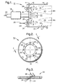
- a gas director plate 24 Mounted adjacent end wall 16, and preferably including end wall 16 as described below, is a gas director plate 24 having a plurality of passages 26 therethrough for receiving a gas 25, for example, air or steam, from an adjacent annular manifold 28 and injecting such gas into chamber 12 in a plurality of gas jets 30 which join to form a generally cylindrical gas curtain 32 surrounding fuel spray 22. Fuel spray 22 is thus desirably shielded by curtain 32 from coming into contact with walls 14.
- a gas director plate 24 having a plurality of passages 26 therethrough for receiving a gas 25, for example, air or steam, from an adjacent annular manifold 28 and injecting such gas into chamber 12 in a plurality of gas jets 30 which join to form a generally cylindrical gas curtain 32 surrounding fuel spray 22.
- Fuel spray 22 is thus desirably shielded by curtain 32 from coming into contact with walls 14.
- passages 26 may be varied as desired, although plates having between twelve and sixteen such passages have been found to provide excellent shielding; first embodiment plate 24 in FIG. 2 is shown as having twelve passages 26, whereas second embodiment plate 24' in FIG. 9 is shown as having sixteen passages 26, for reasons discussed below.
- passages 26 are evenly distributed at equal radii and equal central angle spacing about axis 34 of plate 24.
- each passage axis 36 preferably is inclined to plate axis 24 by an angle 38 (FIG.3), for example, 60°, such that curtain 32 is caused to swirl helically as it flows through chamber 12, causing the injected gas 30 to entrain and mix rapidly with the atomized fuel 22 in an intense, generally annular, mixing zone 40.
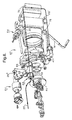
- non-contact fuel vaporizer 10 are incorporated in a hydrocarbon fuel vaporization assembly 42 for supplying a vaporized fuel/air mixture to a fuel combustor such as a hydrocarbon reformer (not shown).
- Atomizing means such as fuel injector 19 is received by a coolant jacket base 44 for injecting fuel through a central opening 46 in a manifold housing 48 containing annular air manifold 28.
- Base 44 is secured to housing 48 via bolts 45.
- Air enters housing 48 via fitting 47.
- a gas director plate 24 mates against housing 48 such that passages 26 are in communication with manifold 28. Plate 24 forms an end of a cylindrical vaporizing chamber 12 and is sealed thereupon by gasket 51.
- Chamber 12 is attached to a plenum 50 receivable of a gas-permeable mixing foam element 52 in known fashion.
- a spark igniter 54 may be mounted with entrance into plenum 50 for igniting the fuel/air mixture upon reformer startup to provide hot combustion products to rapidly heat the reformer to temperature suitable for steady-state catalysis of the mixture.
- Clamps 56 are provided for attaching assembly 42 to the reformer. The assembly is bound together by bolts 58 which thread into threaded ears 60 on chamber 12.
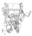
- ambient temperature air 25 is supplied to an inlet leg 61 of a T-fitting 62 wherein the air flow may be divided.
- a bypass air control valve assembly 64 is disposed in a bypass port 66 formed in housing 48 and is connected to a first outlet leg 68 of T-fitting 62.
- a second outlet leg 70 of T-fitting 62 is connected via tubing (omitted for clarity) to a heat exchanger 72, for example, a heat exchanger for heating the air being supplied with fuel/air mixture by non-contact vaporization assembly 42.
- Heated air 25' flows back via tubing (not shown) and enters fitting 47 for use in the vaporizer.
- the flow volume of air through heat exchanger 72 is regulated complementarily by bypass valve assembly 64, and the valve action may be controlled in known fashion in response to temperature in manifold housing 48 as determined by a temperature probe 74.
- a gas director plate in accordance with the invention may be configured to supply more than one gas to vaporizing chamber 12.
- a second embodiment 24' of a director plate arrangement can distribute both a first gas such as air 25 through first manifold 28 and a second gas 78 through a second concentric manifold 80.
- manifolds 28 and 80 are interlocking as shown in FIG. 9 such that eight alternate passages 26a carry first gas 25 and eight alternate passages 26b carry second gas 78.
- providing a second gas can be extremely desirable.
Landscapes
- Engineering & Computer Science (AREA)
- Chemical & Material Sciences (AREA)
- Combustion & Propulsion (AREA)
- Mechanical Engineering (AREA)
- General Engineering & Computer Science (AREA)
- Fuel-Injection Apparatus (AREA)
- Hydrogen, Water And Hydrids (AREA)
Applications Claiming Priority (2)
| Application Number | Priority Date | Filing Date | Title |
|---|---|---|---|
| US39096302A | 2002-07-24 | 2002-07-24 | |
| US390963 | 2002-07-24 |
Publications (2)
| Publication Number | Publication Date |
|---|---|
| EP1384880A2 true EP1384880A2 (fr) | 2004-01-28 |
| EP1384880A3 EP1384880A3 (fr) | 2004-12-15 |
Family
ID=30000652
Family Applications (1)
| Application Number | Title | Priority Date | Filing Date |
|---|---|---|---|
| EP03076682A Withdrawn EP1384880A3 (fr) | 2002-07-24 | 2003-05-30 | Vaporiseur de combustible sans contact |
Country Status (1)
| Country | Link |
|---|---|
| EP (1) | EP1384880A3 (fr) |
Cited By (3)
| Publication number | Priority date | Publication date | Assignee | Title |
|---|---|---|---|---|
| CN109708138A (zh) * | 2018-12-31 | 2019-05-03 | 中国能源建设集团华东电力试验研究院有限公司 | 油枪结焦率降低系统及控制方法 |
| CN111911320A (zh) * | 2020-07-31 | 2020-11-10 | 安庆船用电器有限责任公司 | 一种船用柴油机燃油供给系统的预热装置 |
| CN115621491A (zh) * | 2022-09-07 | 2023-01-17 | 浙江氢邦科技有限公司 | 一种用于固体氧化物燃料电池系统的多功能燃烧器 |
Family Cites Families (10)
| Publication number | Priority date | Publication date | Assignee | Title |
|---|---|---|---|---|
| US3982910A (en) * | 1974-07-10 | 1976-09-28 | The United States Of America As Represented By The Administrator Of The National Aeronautics And Space Administration | Hydrogen-rich gas generator |
| US4022173A (en) * | 1975-08-11 | 1977-05-10 | Read Frank E | Cross-flow vaporizer |
| US4159703A (en) * | 1976-12-10 | 1979-07-03 | The Bendix Corporation | Air assisted fuel atomizer |
| DE3921079A1 (de) * | 1989-06-28 | 1991-01-03 | Bosch Gmbh Robert | Anordnung zur zerstaeubung |
| DE19522075B4 (de) * | 1995-06-17 | 2006-06-29 | Robert Bosch Gmbh | Kraftstoffzuführvorrichtung für einen Verbrennungsmotor |
| EP1094031A4 (fr) * | 1999-04-20 | 2005-02-02 | Tokyo Gas Co Ltd | Reformeur cylindrique monotube et procede pour faire fonctionner ledit reformeur |
| US6533954B2 (en) * | 2000-02-28 | 2003-03-18 | Parker-Hannifin Corporation | Integrated fluid injection air mixing system |
| DE10014347A1 (de) * | 2000-03-24 | 2001-10-04 | Webasto Thermosysteme Gmbh | Zweistoff-Brenner mit Venturirohr-Brennstoffzerstäubung |
| JP3642270B2 (ja) * | 2000-09-12 | 2005-04-27 | 日産自動車株式会社 | 燃料改質装置 |
| DE10055613A1 (de) * | 2000-11-09 | 2002-05-23 | Xcellsis Gmbh | Verfahren zur Zufuhr von Brennstoff und/oder thermischer Energie in einen Gasstrom |
-
2003
- 2003-05-30 EP EP03076682A patent/EP1384880A3/fr not_active Withdrawn
Cited By (5)
| Publication number | Priority date | Publication date | Assignee | Title |
|---|---|---|---|---|
| CN109708138A (zh) * | 2018-12-31 | 2019-05-03 | 中国能源建设集团华东电力试验研究院有限公司 | 油枪结焦率降低系统及控制方法 |
| CN109708138B (zh) * | 2018-12-31 | 2023-11-10 | 中国能源建设集团华东电力试验研究院有限公司 | 油枪结焦率降低系统及控制方法 |
| CN111911320A (zh) * | 2020-07-31 | 2020-11-10 | 安庆船用电器有限责任公司 | 一种船用柴油机燃油供给系统的预热装置 |
| CN111911320B (zh) * | 2020-07-31 | 2021-06-25 | 安庆船用电器有限责任公司 | 一种船用柴油机燃油供给系统的预热装置 |
| CN115621491A (zh) * | 2022-09-07 | 2023-01-17 | 浙江氢邦科技有限公司 | 一种用于固体氧化物燃料电池系统的多功能燃烧器 |
Also Published As
| Publication number | Publication date |
|---|---|
| EP1384880A3 (fr) | 2004-12-15 |
Similar Documents
| Publication | Publication Date | Title |
|---|---|---|
| US20030234455A1 (en) | Non-contacting fuel vaporizer | |
| US20210215124A1 (en) | Multi-physics fluid atomizer and methods | |
| US9803854B2 (en) | Method and apparatus for conditioning liquid hydrocarbon fuels | |
| US7461618B2 (en) | Reformer mixing chamber and method for operating same | |
| EP1323918A2 (fr) | Dispositif d'injection de carburant avec un échangeur de chaleur pour préchauffer le carburant | |
| US7261556B2 (en) | Combustion apparatus for high velocity thermal spraying | |
| US8297537B2 (en) | Atomization system | |
| EP1384880A2 (fr) | Vaporiseur de combustible sans contact | |
| US7188789B2 (en) | Atomising nozzle | |
| US20030186094A1 (en) | Compact precooler | |
| GB2443429A (en) | Fuel Vaporisation Within a Burner Associated With a Combustion Chamber | |
| US7744664B2 (en) | Compact counterflow fuel reformer | |
| US4290031A (en) | Combustor for gas dynamic laser | |
| JP2003054905A (ja) | 燃料電池用改質装置 | |
| JP2605322B2 (ja) | 燃焼器の構造 | |
| JPS5923926Y2 (ja) | 燃焼装置 | |
| JP4260384B2 (ja) | 液体燃料燃焼バーナ | |
| KR100224006B1 (ko) | 석유연소기 | |
| CN121977227A (en) | Regenerative cooling combustion chamber and aeroengine | |
| JPH01203810A (ja) | 液体燃料燃焼装置 | |
| NZ592086A (en) | Fuel conditioning unit comprising a chamber, at least one nozzle and at least one gas port | |
| HK1109444B (en) | Method and apparatus for conditioning liquid fuels | |
| HK1176907A (en) | Multi-physics fuel atomizer and methods |
Legal Events
| Date | Code | Title | Description |
|---|---|---|---|
| PUAI | Public reference made under article 153(3) epc to a published international application that has entered the european phase |
Free format text: ORIGINAL CODE: 0009012 |
|
| AK | Designated contracting states |
Kind code of ref document: A2 Designated state(s): AT BE BG CH CY CZ DE DK EE ES FI FR GB GR HU IE IT LI LU MC NL PT RO SE SI SK TR |
|
| AX | Request for extension of the european patent |
Extension state: AL LT LV MK |
|
| PUAL | Search report despatched |
Free format text: ORIGINAL CODE: 0009013 |
|
| AK | Designated contracting states |
Kind code of ref document: A3 Designated state(s): AT BE BG CH CY CZ DE DK EE ES FI FR GB GR HU IE IT LI LU MC NL PT RO SE SI SK TR |
|
| AX | Request for extension of the european patent |
Extension state: AL LT LV MK |
|
| 17P | Request for examination filed |
Effective date: 20050615 |
|
| AKX | Designation fees paid |
Designated state(s): DE FR GB |
|
| 17Q | First examination report despatched |
Effective date: 20060308 |
|
| GRAP | Despatch of communication of intention to grant a patent |
Free format text: ORIGINAL CODE: EPIDOSNIGR1 |
|
| STAA | Information on the status of an ep patent application or granted ep patent |
Free format text: STATUS: THE APPLICATION IS DEEMED TO BE WITHDRAWN |
|
| 18D | Application deemed to be withdrawn |
Effective date: 20101117 |