EP1384914A2 - Elektrisch betätigte Scheibenbremse - Google Patents
Elektrisch betätigte Scheibenbremse Download PDFInfo
- Publication number
- EP1384914A2 EP1384914A2 EP03077065A EP03077065A EP1384914A2 EP 1384914 A2 EP1384914 A2 EP 1384914A2 EP 03077065 A EP03077065 A EP 03077065A EP 03077065 A EP03077065 A EP 03077065A EP 1384914 A2 EP1384914 A2 EP 1384914A2
- Authority
- EP
- European Patent Office
- Prior art keywords
- piston
- disc brake
- brake assembly
- actuated
- hub
- Prior art date
- Legal status (The legal status is an assumption and is not a legal conclusion. Google has not performed a legal analysis and makes no representation as to the accuracy of the status listed.)
- Granted
Links
- 230000000694 effects Effects 0.000 claims description 6
- 230000007246 mechanism Effects 0.000 claims description 6
- 230000000712 assembly Effects 0.000 description 4
- 238000000429 assembly Methods 0.000 description 4
- 230000009471 action Effects 0.000 description 2
- 238000010276 construction Methods 0.000 description 1
- 210000005069 ears Anatomy 0.000 description 1
- 230000004048 modification Effects 0.000 description 1
- 238000012986 modification Methods 0.000 description 1
- 230000009467 reduction Effects 0.000 description 1
- 230000004044 response Effects 0.000 description 1
Images



Classifications
-
- F—MECHANICAL ENGINEERING; LIGHTING; HEATING; WEAPONS; BLASTING
- F16—ENGINEERING ELEMENTS AND UNITS; GENERAL MEASURES FOR PRODUCING AND MAINTAINING EFFECTIVE FUNCTIONING OF MACHINES OR INSTALLATIONS; THERMAL INSULATION IN GENERAL
- F16D—COUPLINGS FOR TRANSMITTING ROTATION; CLUTCHES; BRAKES
- F16D65/00—Parts or details
- F16D65/14—Actuating mechanisms for brakes; Means for initiating operation at a predetermined position
- F16D65/16—Actuating mechanisms for brakes; Means for initiating operation at a predetermined position arranged in or on the brake
- F16D65/18—Actuating mechanisms for brakes; Means for initiating operation at a predetermined position arranged in or on the brake adapted for drawing members together, e.g. for disc brakes
-
- F—MECHANICAL ENGINEERING; LIGHTING; HEATING; WEAPONS; BLASTING
- F16—ENGINEERING ELEMENTS AND UNITS; GENERAL MEASURES FOR PRODUCING AND MAINTAINING EFFECTIVE FUNCTIONING OF MACHINES OR INSTALLATIONS; THERMAL INSULATION IN GENERAL
- F16D—COUPLINGS FOR TRANSMITTING ROTATION; CLUTCHES; BRAKES
- F16D55/00—Brakes with substantially-radial braking surfaces pressed together in axial direction, e.g. disc brakes
- F16D55/24—Brakes with substantially-radial braking surfaces pressed together in axial direction, e.g. disc brakes with a plurality of axially-movable discs, lamellae, or pads, pressed from one side towards an axially-located member
- F16D55/26—Brakes with substantially-radial braking surfaces pressed together in axial direction, e.g. disc brakes with a plurality of axially-movable discs, lamellae, or pads, pressed from one side towards an axially-located member without self-tightening action
- F16D55/36—Brakes with a plurality of rotating discs all lying side by side
-
- F—MECHANICAL ENGINEERING; LIGHTING; HEATING; WEAPONS; BLASTING
- F16—ENGINEERING ELEMENTS AND UNITS; GENERAL MEASURES FOR PRODUCING AND MAINTAINING EFFECTIVE FUNCTIONING OF MACHINES OR INSTALLATIONS; THERMAL INSULATION IN GENERAL
- F16D—COUPLINGS FOR TRANSMITTING ROTATION; CLUTCHES; BRAKES
- F16D65/00—Parts or details
- F16D65/02—Braking members; Mounting thereof
- F16D65/04—Bands, shoes or pads; Pivots or supporting members therefor
- F16D65/092—Bands, shoes or pads; Pivots or supporting members therefor for axially-engaging brakes, e.g. disc brakes
- F16D65/095—Pivots or supporting members therefor
-
- F—MECHANICAL ENGINEERING; LIGHTING; HEATING; WEAPONS; BLASTING
- F16—ENGINEERING ELEMENTS AND UNITS; GENERAL MEASURES FOR PRODUCING AND MAINTAINING EFFECTIVE FUNCTIONING OF MACHINES OR INSTALLATIONS; THERMAL INSULATION IN GENERAL
- F16D—COUPLINGS FOR TRANSMITTING ROTATION; CLUTCHES; BRAKES
- F16D55/00—Brakes with substantially-radial braking surfaces pressed together in axial direction, e.g. disc brakes
- F16D2055/0004—Parts or details of disc brakes
- F16D2055/0008—Brake supports
- F16D2055/0012—Brake supports integral with vehicle suspension
-
- F—MECHANICAL ENGINEERING; LIGHTING; HEATING; WEAPONS; BLASTING
- F16—ENGINEERING ELEMENTS AND UNITS; GENERAL MEASURES FOR PRODUCING AND MAINTAINING EFFECTIVE FUNCTIONING OF MACHINES OR INSTALLATIONS; THERMAL INSULATION IN GENERAL
- F16D—COUPLINGS FOR TRANSMITTING ROTATION; CLUTCHES; BRAKES
- F16D55/00—Brakes with substantially-radial braking surfaces pressed together in axial direction, e.g. disc brakes
- F16D2055/0004—Parts or details of disc brakes
- F16D2055/0016—Brake calipers
-
- F—MECHANICAL ENGINEERING; LIGHTING; HEATING; WEAPONS; BLASTING
- F16—ENGINEERING ELEMENTS AND UNITS; GENERAL MEASURES FOR PRODUCING AND MAINTAINING EFFECTIVE FUNCTIONING OF MACHINES OR INSTALLATIONS; THERMAL INSULATION IN GENERAL
- F16D—COUPLINGS FOR TRANSMITTING ROTATION; CLUTCHES; BRAKES
- F16D2121/00—Type of actuator operation force
- F16D2121/14—Mechanical
-
- F—MECHANICAL ENGINEERING; LIGHTING; HEATING; WEAPONS; BLASTING
- F16—ENGINEERING ELEMENTS AND UNITS; GENERAL MEASURES FOR PRODUCING AND MAINTAINING EFFECTIVE FUNCTIONING OF MACHINES OR INSTALLATIONS; THERMAL INSULATION IN GENERAL
- F16D—COUPLINGS FOR TRANSMITTING ROTATION; CLUTCHES; BRAKES
- F16D2121/00—Type of actuator operation force
- F16D2121/18—Electric or magnetic
- F16D2121/24—Electric or magnetic using motors
-
- F—MECHANICAL ENGINEERING; LIGHTING; HEATING; WEAPONS; BLASTING
- F16—ENGINEERING ELEMENTS AND UNITS; GENERAL MEASURES FOR PRODUCING AND MAINTAINING EFFECTIVE FUNCTIONING OF MACHINES OR INSTALLATIONS; THERMAL INSULATION IN GENERAL
- F16D—COUPLINGS FOR TRANSMITTING ROTATION; CLUTCHES; BRAKES
- F16D2123/00—Multiple operation forces
-
- F—MECHANICAL ENGINEERING; LIGHTING; HEATING; WEAPONS; BLASTING
- F16—ENGINEERING ELEMENTS AND UNITS; GENERAL MEASURES FOR PRODUCING AND MAINTAINING EFFECTIVE FUNCTIONING OF MACHINES OR INSTALLATIONS; THERMAL INSULATION IN GENERAL
- F16D—COUPLINGS FOR TRANSMITTING ROTATION; CLUTCHES; BRAKES
- F16D2125/00—Components of actuators
- F16D2125/18—Mechanical mechanisms
- F16D2125/20—Mechanical mechanisms converting rotation to linear movement or vice versa
- F16D2125/22—Mechanical mechanisms converting rotation to linear movement or vice versa acting transversely to the axis of rotation
- F16D2125/24—Rack-and-pinion
-
- F—MECHANICAL ENGINEERING; LIGHTING; HEATING; WEAPONS; BLASTING
- F16—ENGINEERING ELEMENTS AND UNITS; GENERAL MEASURES FOR PRODUCING AND MAINTAINING EFFECTIVE FUNCTIONING OF MACHINES OR INSTALLATIONS; THERMAL INSULATION IN GENERAL
- F16D—COUPLINGS FOR TRANSMITTING ROTATION; CLUTCHES; BRAKES
- F16D2125/00—Components of actuators
- F16D2125/18—Mechanical mechanisms
- F16D2125/20—Mechanical mechanisms converting rotation to linear movement or vice versa
- F16D2125/34—Mechanical mechanisms converting rotation to linear movement or vice versa acting in the direction of the axis of rotation
- F16D2125/40—Screw-and-nut
Definitions
- the invention relates generally to disc brake assemblies having two or more brake discs axially slideable along a hub, and more particularly to the means for actuating sliding movement of such discs.
- Electrically actuated disc brake systems are known in which an electrical actuator is used to move brake pads into and out of engagement with a single disc that is fixed to a rotatable hub.
- electrical systems having a power source of 24 volts or greater would be used to achieve the force necessary to prevent relative rotational movement between a single disc brake assembly and a pair of opposing brake pads.
- an electric motor capable of exerting the necessary forces must be used. Therefore, in addition to the 24 volt or greater power source, a sizable electric motor is typically used to generate the braking forces required in a single fixed disc brake assembly.
- electrically actuated brake systems have not been widely accepted due to the size and demands of an appropriate electric actuator.
- Sliding disc-type brake systems are also known in which one or more brake discs are supported on a rotating hub and rotate with the hub as well as slide axially along the hub. Hydraulically actuated brake pads move into and out of engagement with the sliding disc(s) to effect selective braking action.
- a disc brake assembly constructed according to the present invention comprises a hub that is rotatable about an axis and on which at least a pair of brake discs are supported for rotation with the hub and for axial sliding movement relative to the hub along the axis.
- the discs have opposite sides presenting braking surfaces.
- a non-rotatable support structure supports a plurality of friction elements for relative axial movement into and out of frictional braking engagement with the braking surfaces of the discs.
- An electric actuator is mounted on the support structure adjacent at least one of the friction elements and is operative when actuated to move the friction elements into frictional braking engagement with the braking surfaces of the discs.
- the sliding disc brake system of the invention employs multiple sliding brake discs, and thus presents a multiple of braking surfaces, the forces required by the electric actuator are half or less of the forces needed to actuate single fixed disc systems of the prior art. Consequently, a comparably smaller electric actuator can be used, lending to an overall reduction in the package size of the brake system.
- the smaller electric actuator also has a relatively lower voltage requirement, and as such draws less of the available electric power from the vehicle.
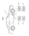
- Figure 1 shows a vehicle 10 equipped with an electrically actuated disc brake assembly 12 constructed according to a presently preferred embodiment of the invention.
- the disc brake assembly 12 has a hub 14 that is rotatable about an axis 16.
- the hub 14 supports at least a pair of discs 18, 19 for relative axial movement along the axis 16 and for conjoint rotation with the hub 14 about the axis 16.
- a nonrotatable support structure 24 supports a plurality of friction elements or brake pads 26 for relative axial movement into and out of frictional braking engagement with the discs 18, 19.
- a primary electric actuator 28 is mounted on the support structure 24 adjacent at least one of the friction elements 26 and is operative when actuated to move the friction elements 26 into and out of frictional braking engagement with the discs 18, 19.
- the support structure 24 of the disc brake assembly 12 includes a support body 30 having a knuckle portion 32, a bridge portion 34, and an end plate portion 36.
- the knuckle portion 32 has an opening 38 formed in a mounting flange 40 of the knuckle portion 32 for receiving a strut (not shown).
- the opening 38 has an axis 42 about which the disc brake assembly 12 pivots on the strut.
- An opening 44 is formed in a lower section 46 of the knuckle portion 32 for receiving a pin of a ball joint on a tie bar (not shown).
- An arm section 48 extends laterally from the knuckle portion 32 and has an opening 50 for receiving a track bar (not shown) to enable the disc brake assembly 12 to rotate about the axis 42 in order to turn wheels of the vehicle 10.
- a generally cylindrical piston bore 54 is formed in the knuckle portion 32 and receives a piston 56 for reciprocating movement therein.
- a motor chamber 58 is preferably formed and adjacent and preferably generally concentric to the piston chamber 54 and coextensive with a bottom surface 60 of the piston chamber 54.
- the motor chamber 58 receives a motor 62 which is coupled operatively to the piston 56 for reciprocating the piston 56 within the piston chamber 54.
- a port 64 extends into the motor chamber 58 and accommodates suitable wiring 66 for the motor 62.
- a counterbore 68 supports a secondary actuator 72 which operates to selectively move the piston 56 independently of the actuation of the primary actuator 28. Further details concerning the construction and operation of the actuators 28, 72 are described below.
- the bridge portion 34 of the disc brake assembly 12 has an end 73 spaced from the knuckle portion 32 and preferably a pair of threaded fastener openings to facilitate fastening the bridge portion 34 to the knuckle portion 32 by a pair of fasteners 74.
- a top surface 76 of the bridge portion 34 preferably has a pair of fastener openings enabling a spring device 80 to be fastened to the top surface 76 of the bridge portion 34 by a pair of fasteners 82.
- the bridge portion 34 has a pair of opposite sides 84 presenting a generally stepped slideway 86, as best shown in Figure 7, along which a plurality of brake pad assemblies, shown here as an inner, intermediate, and outer brake pad assembly 88, 89, 90, respectively, slide axially.
- a plurality of brake pad assemblies shown here as an inner, intermediate, and outer brake pad assembly 88, 89, 90, respectively, slide axially.
- the slideway can be formed in a variety of shapes and contours, and that the slideway need not have a generally stepped contour as shown here.
- the brake pad assemblies 88, 89, 90 have the friction elements or brake pads 26 fixed thereto and are slidably supported by the slideway 86 of the bridge portion 34 for relative axial movement along the bridge portion 34.
- the brake pads 26 slide into frictional engagement with the discs 18, 19, as best shown in Figure 2, and when unactuated, slide out of frictional engagement with the discs 18, 19, as best shown in Figure 3.
- the spring device 80 fastened to the top surface 76 of the bridge portion 34 exerts a force on the brake pad assemblies 88, 89, 90 to prevent them from rattling on the bridge portion 34.
- the hub 14 is generally cylindrical and has an outer surface 92 with a plurality of axial slots or grooves 94 preferably extending the length of outer surface 92.
- the hub 14 is rotatably supported by the knuckle portion 32 for relative rotation thereto.
- the discs 18, 19 preferably have inwardly extending ears or projections 96 that are slideably received within the grooves 94 in the hub 14, as best shown in Figure 6, for relative axial movement along at least a portion the length of the hub 14.
- the discs 18, 19 are received between the brake pads 26 and have opposite sides presenting respective braking surfaces 100 which are selectively engaged by the brake pads 26. While the projections 96 of the discs 18, 19 allow the discs to slide freely axially within the grooves 94 of the hub, the projections 96 engage the hub 14 in a circumferential direction and provide for conjoint rotation of the discs 18, 19 with the hub 14.
- the projections in effect, provide a splined connection between the discs 18, 19 and hub 14, enabling the discs 18, 19 to slide axially along the hub 14, while supporting the discs 18, 19 against relative rotation on the hub 14, so that the discs 18, 19 rotate with the hub 14.
- the electric motor 62 drives a ball-screw type device of the general type shown in U.S. Patent No. 6,282,971 B1 to Shirai et al. which is incorporated herein in its entirety.
- the ball-screw has a rotatable screw portion 104 and a nut portion 106.
- the screw portion 104 is driven by the motor 62 and extends into a bore 102 of the piston 56.
- the nut 106 is fixed within the bore 102 and carries a plurality of recyclable balls 107 which cooperate with helical ball grooves of the screw 104 to effect axial movement of the nut 106, and thus the piston 56 along the screw 104 in response to rotating the screw 104 in one direction or the other.
- the piston 56 has retainers 109 that extend into axial guides 111 of the knuckle portion 32 to support the piston 56 against rotation in the piston bore 54 during rotation of the screw 104.
- Figure 2 shows the piston 56 in an extended, actuated position, in which the piston 56 is moved outwardly into contact with the brake pad 88, sliding it and brake pad 89 along with the discs 18, 19 axially outwardly and into stacked, frictional contact with one another against the fixed end pad 90 mounted on the bridge 34. Reversing the drive of the screw 104 via the electric motor 62 drives the nut 106 back in the opposite direction, causing the piston 56 to move to the retracted, non-actuated position shown in Figure 3.
- a shaft of the motor 62 forms the screw portion 104, and preferably extends through the electric motor 62 so that an end 110 of the screw portion 104 extends beyond an end 112 of the electric motor 62.
- a drive mechanism shown here as a driven gear 114, is preferably attached adjacent the end 110 of the screw portion 104 for engagement and disengagement with the secondary actuator 72.
- the driven gear 114 is shown here as a spur gear, though it should be recognized that the driven gear 114 can be any type of toothed gear to facilitate operable connection to the secondary actuator 72.
- the electric motor 62 of the primary actuator 28 is connected to the vehicle via a primary controller 118 so that when a user actuates the primary actuator 28, preferably by a brake pedal 119, a signal is sent to the primary controller 118 and then to the electric motor 62 to actuate the primary actuator 28, thus bringing the brake pads 26 into frictional engagement with the discs 18, 19.
- the electric motor is powered by a 12 volt or less power source, as is commonly provided as a power source in automobiles.
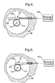
- the secondary actuator 72 is coupled operatively to the piston 56 by way of a secondary controller 124, as shown in Figures 1, 4 and 5, and can either be electrically or mechanically actuated independently from the electric motor 62.
- the secondary actuator 72 is operative when actuated to move the piston 56 toward the inner brake pad assembly 88 and to move the brake pads 26 into frictional engagement with the discs 18, 19 independent of the primary actuator 28.
- the secondary actuator 72 has a drive mechanism shown here as a drive gear 120, represented as a rack style gear, having teeth 122 to engage and disengage the spur gear 114.
- the secondary actuator 72 is shown as a rack and spur gear arrangement, any other suitable mechanical or electrical operative connection between the screw and the secondary actuator could be used.
- the secondary actuator 72 can be used as an emergency brake, overriding the operation of the primary actuator 28.
Landscapes
- Engineering & Computer Science (AREA)
- General Engineering & Computer Science (AREA)
- Mechanical Engineering (AREA)
- Braking Arrangements (AREA)
Applications Claiming Priority (2)
| Application Number | Priority Date | Filing Date | Title |
|---|---|---|---|
| US202771 | 2002-07-24 | ||
| US10/202,771 US6991075B2 (en) | 2002-07-24 | 2002-07-24 | Electrically actuated disc brake assembly |
Publications (3)
| Publication Number | Publication Date |
|---|---|
| EP1384914A2 true EP1384914A2 (de) | 2004-01-28 |
| EP1384914A3 EP1384914A3 (de) | 2005-03-16 |
| EP1384914B1 EP1384914B1 (de) | 2007-06-06 |
Family
ID=30000108
Family Applications (1)
| Application Number | Title | Priority Date | Filing Date |
|---|---|---|---|
| EP03077065A Expired - Lifetime EP1384914B1 (de) | 2002-07-24 | 2003-07-02 | Elektrisch betätigte Scheibenbremse |
Country Status (3)
| Country | Link |
|---|---|
| US (2) | US6991075B2 (de) |
| EP (1) | EP1384914B1 (de) |
| DE (1) | DE60314206T2 (de) |
Cited By (2)
| Publication number | Priority date | Publication date | Assignee | Title |
|---|---|---|---|---|
| DE102005058042B4 (de) * | 2004-12-07 | 2014-01-23 | Advics Co., Ltd. | Motorbetriebenes Bremsgerät für ein Fahrzeug |
| FR3038952A1 (fr) * | 2016-02-18 | 2017-01-20 | Foundation Brakes France | Frein a disque de vehicule automobile comportant une piece d'anti-rotation entre l'etrier et un piston du frein |
Families Citing this family (5)
| Publication number | Priority date | Publication date | Assignee | Title |
|---|---|---|---|---|
| US20040200676A1 (en) * | 2003-04-08 | 2004-10-14 | Huang-Tsang Chang | Electric sliding disc brake system |
| US7458442B2 (en) * | 2005-03-23 | 2008-12-02 | Honeywell International Inc. | Electric brake having parking brake function |
| JP2012122574A (ja) * | 2010-12-10 | 2012-06-28 | Hitachi Industrial Equipment Systems Co Ltd | 電磁ブレーキ及び電動機 |
| CN102182775B (zh) * | 2011-04-15 | 2013-05-01 | 清华大学 | 用于汽车分布式电子液压制动系统的制动执行机构 |
| DE102016209537A1 (de) * | 2015-12-02 | 2017-06-08 | Continental Teves Ag & Co. Ohg | Bremsdrucksteuergerät |
Citations (1)
| Publication number | Priority date | Publication date | Assignee | Title |
|---|---|---|---|---|
| US6282971B1 (en) | 1998-06-26 | 2001-09-04 | Thk Co., Ltd. | Ball screw |
Family Cites Families (30)
| Publication number | Priority date | Publication date | Assignee | Title |
|---|---|---|---|---|
| US3612619A (en) * | 1969-02-24 | 1971-10-12 | Henry L Hayes | Safety brake apparatus |
| US4542809A (en) * | 1979-07-30 | 1985-09-24 | Goodyear Aerospace Corporation | Electrically actuated aircraft brakes |
| US4381049A (en) * | 1979-07-30 | 1983-04-26 | Goodyear Aerospace Corporation | Electrically actuated aircraft brakes |
| US4567967A (en) * | 1979-07-30 | 1986-02-04 | Goodyear Aerospace Corporation | Electrically actuated aircraft brakes |
| US4529067A (en) * | 1983-08-31 | 1985-07-16 | Rockwell International Corporation | Multiple disc brake |
| FR2590219B1 (fr) * | 1985-11-20 | 1991-02-01 | Bendix France | Dispositif de freinage electrique pour vehicule |
| FR2600387B1 (fr) * | 1986-06-23 | 1990-08-10 | Wabco Westinghouse | Systeme de frein d'immobilisation pour vehicule et etrier de frein pour un tel systeme |
| US4865162A (en) * | 1986-12-15 | 1989-09-12 | Opus Acquisition Corporation | Electrically actuated aircraft brakes |
| US4995483A (en) * | 1989-12-18 | 1991-02-26 | Aircraft Braking Systems Corporation | Motor position feedback controlled electrically actuated aircraft brake |
| JPH03265725A (ja) * | 1990-03-12 | 1991-11-26 | Mitsubishi Heavy Ind Ltd | 電気作動式車輪ブレーキ |
| JPH03264725A (ja) | 1990-03-14 | 1991-11-26 | Yanmar Diesel Engine Co Ltd | 内燃機関の副室式燃焼室 |
| US5603395A (en) * | 1992-03-05 | 1997-02-18 | Easom Engineering & Mfg. Corp. | Electrically actuated disc stack having low response time due to reduced residual magnetism for use in drives, brakes and combinations thereof |
| JPH0713898A (ja) * | 1993-06-29 | 1995-01-17 | Mitsubishi Electric Corp | 半導体集積回路装置 |
| US5661384A (en) * | 1995-06-05 | 1997-08-26 | Lucas Western, Inc. | Motor control system and method |
| GB9519468D0 (en) * | 1995-09-23 | 1995-11-22 | Smithkline Beecham Plc | Novel process |
| US5706918A (en) * | 1995-12-26 | 1998-01-13 | General Motors Corporation | Brake apply mechanism |
| BR9711849A (pt) | 1996-10-03 | 1999-08-24 | Toyota Motor Co Ltd | Sistema de frenagem que inclui freio de disco acionado por motor equipado com mecanismo auto-servo |
| US6003640A (en) * | 1997-05-09 | 1999-12-21 | The B.F. Goodrich Company | Electronic braking system with brake wear measurement and running clearance adjustment |
| NL1006543C2 (nl) | 1997-07-10 | 1999-01-12 | Skf Ind Trading & Dev | Elektrische actuator en remklauw met een dergelijke actuator. |
| US6325182B1 (en) | 1998-03-27 | 2001-12-04 | Tokico, Ltd. | Motor-driven brake system |
| US6402259B2 (en) * | 1999-07-14 | 2002-06-11 | Goodrich Corporation | Electromechanical braking system with power distribution and redundancy |
| US6581730B1 (en) * | 1999-09-13 | 2003-06-24 | Goodrich Corporation | Aircraft landing gear with integrated brake actuation system |
| JP3736225B2 (ja) * | 1999-09-14 | 2006-01-18 | 日産自動車株式会社 | 電動ブレーキ装置 |
| US6412610B1 (en) * | 1999-11-24 | 2002-07-02 | Delphi Technologies, Inc. | Electric brake caliper |
| JP4399754B2 (ja) * | 2000-05-31 | 2010-01-20 | 日立オートモティブシステムズ株式会社 | 電動ディスクブレーキ |
| DE10035220B4 (de) * | 2000-07-20 | 2014-01-23 | Robert Bosch Gmbh | Verfahren zum Betrieb einer Radbremsvorrichtung |
| GB0018154D0 (en) * | 2000-07-25 | 2000-09-13 | Federal Mogul Brake Systems Li | Apparatus and method for controlling a braking system |
| US6412613B1 (en) * | 2000-11-16 | 2002-07-02 | Midwest Brake Bond Company | Electric brake |
| FR2819469B1 (fr) * | 2001-01-18 | 2003-02-28 | Sagem | Actionneur electromecanique de frein a disques multiples pour moyen de transport, notamment pour avion |
| US8100232B2 (en) * | 2001-08-16 | 2012-01-24 | Wabco Gmbh | Actuating device for a brake |
-
2002
- 2002-07-24 US US10/202,771 patent/US6991075B2/en not_active Expired - Lifetime
-
2003
- 2003-07-02 DE DE60314206T patent/DE60314206T2/de not_active Expired - Lifetime
- 2003-07-02 EP EP03077065A patent/EP1384914B1/de not_active Expired - Lifetime
-
2004
- 2004-03-09 US US10/796,227 patent/US7182183B2/en not_active Expired - Lifetime
Patent Citations (1)
| Publication number | Priority date | Publication date | Assignee | Title |
|---|---|---|---|---|
| US6282971B1 (en) | 1998-06-26 | 2001-09-04 | Thk Co., Ltd. | Ball screw |
Cited By (2)
| Publication number | Priority date | Publication date | Assignee | Title |
|---|---|---|---|---|
| DE102005058042B4 (de) * | 2004-12-07 | 2014-01-23 | Advics Co., Ltd. | Motorbetriebenes Bremsgerät für ein Fahrzeug |
| FR3038952A1 (fr) * | 2016-02-18 | 2017-01-20 | Foundation Brakes France | Frein a disque de vehicule automobile comportant une piece d'anti-rotation entre l'etrier et un piston du frein |
Also Published As
| Publication number | Publication date |
|---|---|
| US6991075B2 (en) | 2006-01-31 |
| US7182183B2 (en) | 2007-02-27 |
| US20040168866A1 (en) | 2004-09-02 |
| EP1384914A3 (de) | 2005-03-16 |
| EP1384914B1 (de) | 2007-06-06 |
| DE60314206T2 (de) | 2008-01-31 |
| DE60314206D1 (de) | 2007-07-19 |
| US20040016606A1 (en) | 2004-01-29 |
Similar Documents
| Publication | Publication Date | Title |
|---|---|---|
| KR101681035B1 (ko) | 전기기계식 차량 브레이크 | |
| KR910007579B1 (ko) | 전기 작동식 디스크 브레이크 | |
| KR100678871B1 (ko) | 전자기계식 휠 브레이크 장치 | |
| US6761252B1 (en) | Partially lined disk brake with electromechanical actuator unit | |
| US6095293A (en) | Aircraft brake and method with electromechanical actuator modules | |
| CN101627221B (zh) | 用于车辆制动器组件的电致动器单元 | |
| JP6602305B2 (ja) | 不可逆なねじナットシステムを有するアクチュエータ、ドラムブレーキ、およびこれを備えるブレーキ装置 | |
| US6684988B2 (en) | Drum brake and electric actuator therefor | |
| EP3907415A1 (de) | Bremsanordnung mit einem festen und einem schwimmenden bremssattelsystem und ein verfahren zur anwendung einer bremse | |
| JP2017502230A (ja) | 軸線方向のガイドレールを有する、ギヤによって駆動されるアクチュエータ、およびこれを備えるドラムブレーキおよびブレーキ装置 | |
| KR102957215B1 (ko) | 전기 기계식 브레이크 및 이의 작동방법 | |
| EP2165899B1 (de) | Feststellbremsenmechanismus | |
| EP1214531B1 (de) | Elektrisches bremsbetätigungsmodul für flugzeuge | |
| US6991075B2 (en) | Electrically actuated disc brake assembly | |
| US6142265A (en) | Arrangement for operating a brake of a vehicle | |
| JP2009535587A (ja) | ブレーキキャリパー | |
| US20040200676A1 (en) | Electric sliding disc brake system | |
| JP4444665B2 (ja) | 非常解放及び一時解放のための電動操作可能な装置を備えたブレーキ締め付け装置 | |
| JP4444666B2 (ja) | 電気操作式の磨耗後調節装置および非常および補助緊締解除装置を備えたブレーキ緊締装置 | |
| JP4321916B2 (ja) | モータ駆動ドラムブレーキ用アクチュエータ | |
| HU224799B1 (en) | Braking device | |
| JP2010025313A (ja) | 電動ブレーキ装置 | |
| JP2001173693A (ja) | モータ駆動ブレーキ用アクチュエータ | |
| US20250207647A1 (en) | Brake actuator and brake apparatus including the same | |
| JP2024078366A (ja) | 車両用ブレーキ装置 |
Legal Events
| Date | Code | Title | Description |
|---|---|---|---|
| PUAI | Public reference made under article 153(3) epc to a published international application that has entered the european phase |
Free format text: ORIGINAL CODE: 0009012 |
|
| AK | Designated contracting states |
Kind code of ref document: A2 Designated state(s): AT BE BG CH CY CZ DE DK EE ES FI FR GB GR HU IE IT LI LU MC NL PT RO SE SI SK TR |
|
| AX | Request for extension of the european patent |
Extension state: AL LT LV MK |
|
| PUAL | Search report despatched |
Free format text: ORIGINAL CODE: 0009013 |
|
| AK | Designated contracting states |
Kind code of ref document: A3 Designated state(s): AT BE BG CH CY CZ DE DK EE ES FI FR GB GR HU IE IT LI LU MC NL PT RO SE SI SK TR |
|
| AX | Request for extension of the european patent |
Extension state: AL LT LV MK |
|
| 17P | Request for examination filed |
Effective date: 20050916 |
|
| AKX | Designation fees paid |
Designated state(s): DE FR GB |
|
| 17Q | First examination report despatched |
Effective date: 20060707 |
|
| GRAP | Despatch of communication of intention to grant a patent |
Free format text: ORIGINAL CODE: EPIDOSNIGR1 |
|
| GRAS | Grant fee paid |
Free format text: ORIGINAL CODE: EPIDOSNIGR3 |
|
| GRAA | (expected) grant |
Free format text: ORIGINAL CODE: 0009210 |
|
| AK | Designated contracting states |
Kind code of ref document: B1 Designated state(s): DE FR GB |
|
| REG | Reference to a national code |
Ref country code: GB Ref legal event code: FG4D |
|
| REF | Corresponds to: |
Ref document number: 60314206 Country of ref document: DE Date of ref document: 20070719 Kind code of ref document: P |
|
| ET | Fr: translation filed | ||
| PLBE | No opposition filed within time limit |
Free format text: ORIGINAL CODE: 0009261 |
|
| STAA | Information on the status of an ep patent application or granted ep patent |
Free format text: STATUS: NO OPPOSITION FILED WITHIN TIME LIMIT |
|
| 26N | No opposition filed |
Effective date: 20080307 |
|
| GBPC | Gb: european patent ceased through non-payment of renewal fee |
Effective date: 20070906 |
|
| PG25 | Lapsed in a contracting state [announced via postgrant information from national office to epo] |
Ref country code: GB Free format text: LAPSE BECAUSE OF NON-PAYMENT OF DUE FEES Effective date: 20070906 |
|
| PGFP | Annual fee paid to national office [announced via postgrant information from national office to epo] |
Ref country code: FR Payment date: 20120719 Year of fee payment: 10 |
|
| REG | Reference to a national code |
Ref country code: FR Ref legal event code: ST Effective date: 20140331 |
|
| PG25 | Lapsed in a contracting state [announced via postgrant information from national office to epo] |
Ref country code: FR Free format text: LAPSE BECAUSE OF NON-PAYMENT OF DUE FEES Effective date: 20130731 |
|
| PGFP | Annual fee paid to national office [announced via postgrant information from national office to epo] |
Ref country code: DE Payment date: 20180619 Year of fee payment: 16 |
|
| REG | Reference to a national code |
Ref country code: DE Ref legal event code: R119 Ref document number: 60314206 Country of ref document: DE |
|
| REG | Reference to a national code |
Ref country code: DE Ref legal event code: R081 Ref document number: 60314206 Country of ref document: DE Owner name: BWI COMPANY LIMITED S.A., LU Free format text: FORMER OWNER: DELPHI TECHNOLOGIES, INC., TROY, MICH., US Ref country code: DE Ref legal event code: R082 Ref document number: 60314206 Country of ref document: DE |
|
| PG25 | Lapsed in a contracting state [announced via postgrant information from national office to epo] |
Ref country code: DE Free format text: LAPSE BECAUSE OF NON-PAYMENT OF DUE FEES Effective date: 20200201 |