EP1384959A2 - Turbogénérateur pour chauffe-eau - Google Patents
Turbogénérateur pour chauffe-eau Download PDFInfo
- Publication number
- EP1384959A2 EP1384959A2 EP03380163A EP03380163A EP1384959A2 EP 1384959 A2 EP1384959 A2 EP 1384959A2 EP 03380163 A EP03380163 A EP 03380163A EP 03380163 A EP03380163 A EP 03380163A EP 1384959 A2 EP1384959 A2 EP 1384959A2
- Authority
- EP
- European Patent Office
- Prior art keywords
- pipe
- conduit
- alternator
- generator assembly
- turbo generator
- Prior art date
- Legal status (The legal status is an assumption and is not a legal conclusion. Google has not performed a legal analysis and makes no representation as to the accuracy of the status listed.)
- Withdrawn
Links
- XLYOFNOQVPJJNP-UHFFFAOYSA-N water Substances O XLYOFNOQVPJJNP-UHFFFAOYSA-N 0.000 title claims abstract description 36
- 230000008878 coupling Effects 0.000 claims abstract description 8
- 238000010168 coupling process Methods 0.000 claims abstract description 8
- 238000005859 coupling reaction Methods 0.000 claims abstract description 8
- 239000002991 molded plastic Substances 0.000 claims abstract description 3
- 230000015572 biosynthetic process Effects 0.000 claims abstract 2
- 238000007789 sealing Methods 0.000 claims description 4
- 230000000712 assembly Effects 0.000 description 2
- 238000000429 assembly Methods 0.000 description 2
- 238000010276 construction Methods 0.000 description 2
- 230000002093 peripheral effect Effects 0.000 description 2
- 238000001514 detection method Methods 0.000 description 1
- 239000002737 fuel gas Substances 0.000 description 1
- 238000000465 moulding Methods 0.000 description 1
- 238000005192 partition Methods 0.000 description 1
- 230000001105 regulatory effect Effects 0.000 description 1
- 238000000926 separation method Methods 0.000 description 1
- 238000011144 upstream manufacturing Methods 0.000 description 1
Images

Classifications
-
- F—MECHANICAL ENGINEERING; LIGHTING; HEATING; WEAPONS; BLASTING
- F24—HEATING; RANGES; VENTILATING
- F24H—FLUID HEATERS, e.g. WATER OR AIR HEATERS, HAVING HEAT-GENERATING MEANS, e.g. HEAT PUMPS, IN GENERAL
- F24H1/00—Water heaters, e.g. boilers, continuous-flow heaters or water-storage heaters
-
- F—MECHANICAL ENGINEERING; LIGHTING; HEATING; WEAPONS; BLASTING
- F24—HEATING; RANGES; VENTILATING
- F24D—DOMESTIC- OR SPACE-HEATING SYSTEMS, e.g. CENTRAL HEATING SYSTEMS; DOMESTIC HOT-WATER SUPPLY SYSTEMS; ELEMENTS OR COMPONENTS THEREFOR
- F24D18/00—Small-scale combined heat and power [CHP] generation systems specially adapted for domestic heating, space heating or domestic hot-water supply
-
- F—MECHANICAL ENGINEERING; LIGHTING; HEATING; WEAPONS; BLASTING
- F24—HEATING; RANGES; VENTILATING
- F24D—DOMESTIC- OR SPACE-HEATING SYSTEMS, e.g. CENTRAL HEATING SYSTEMS; DOMESTIC HOT-WATER SUPPLY SYSTEMS; ELEMENTS OR COMPONENTS THEREFOR
- F24D2101/00—Electric generators of small-scale CHP systems
- F24D2101/10—Gas turbines; Steam engines or steam turbines; Water turbines, e.g. located in water pipes
Definitions
- the present invention relates to an electric power generating unit actuated by a hydraulic turbine for mounting in a domestic water heater, wherein the turbine is associated with the generator dynamo-electric alternator and interposed in the water heater conduit.
- Miniature-sized turbine power generating assemblies for water heaters that produce a peak electric current of around 100 mA are already known. They are made up of a dynamo-electric alternator and a longitudinal portion of water conduit pipe , which is interposed in the sanitary cold water circuit. The portion of pipe has a built-in minimum water pressure discharge valve and the turbine is driven by a flow of water shunted from the heater sanitary water circuit, parallel to the valve and bypassing it.
- the alternator body is mounted on the turbo generator conduit pipe and coupled to it with a watertight joint.
- the alternator rotor is the permanent magnet type and its shaft is shared by the turbine, so that the rotor is housed in a chamber in contact with the current of water that impels the turbine.
- the turbine is wholly immersed in a flow of actuating water shunted from the heater water flow and parallel to it.
- the bypass conduit for the actuating flow is formed by moulding outside the heater flow conduit pipe, below a base of the alternator body, and it is screwed to the conduit pipe.
- the object of the present invention is a miniature electrical turbo generator assembly for a domestic water heater which is inserted in the sanitary cold water conduit circuit, as defined in claim 1.
- the main heater circuit conduit with a discharge valve, the conduit for the turbine actuating flow, the turbine housing chamber, and the means for coupling the alternator to the turbine are constructed wholly inside a section of conduit pipe moulded with a substantially cylindrical external configuration.
- the alternator body housing the magnet rotor and supporting the drive shaft is of simple construction, as the preferably toroidal shaped stator is mounted on a rotor body, which is coupled directly to this portion of pipe, and in this way only one body is formed for the magnet rotor for recess coupling.
- the parallel conduit for actuating the turbine wheel is formed inside the portion of main conduit pipe.
- the parallel duct inlet and outlet and the arrangement of the vane wheel in it are adapted to reduce the pressure drop in the bypass conduit actuating flow.
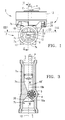
- an embodiment of turbo generator assembly 1 for a domestic water heater in accordance with the present invention comprises: an alternator 2 with a permanent magnet rotor 3, a turbine wheel 5 turning a drive shaft 4 common to the magnet rotor 3, and a preferably toroidal shaped stator 13 encircling a alternator body 6, a longitudinal portion of conduit pipe 7, which is inserted in the sanitary water circuit 19 of a heater, and it has a flat inner wall 7c extended in the axial direction of the pipe 7 for its division into a main conduit 17, provided with a discharge valve 8, and a bypass conduit in which the turbine wheel 5 is interposed.
- the dividing wall 7c thereby establishes two water flows, a main flow 17', which is controlled by the discharge valve 8, and an actuating flow 18' for the wheel 5, which bypasses the discharge valve 8.
- the alternator body 6 houses a rotor chamber 14, and the pipe 7 also comprises a turbine chamber 9 formed integral with the pipe 7 and isolated from the rotor chamber 14.
- both are provided with direct recess coupling means 6b, 7b and means 6b,23,24 for the watertight sealing of the rotor chamber 14.
- the conduit pipe 7 has an approximate length of 77 mm, an outside diameter of 24 mm, inside diameter of around 17 mm, the magnet rotor 3 has a diameter of 20 mm, and the turbine wheel has a diameter of 12 mm.
- the alternator body 6 is made of tubular-shaped moulded plastic with a dome 6a on the body which forms the magnet rotor chamber, and a tubular part 6b for mounting on the tube 7.
- the stator 13 is mounted around the dome 6a and the drive shaft 4 is supported with one end on a support 15 on this dome 6a and with the opposite end at the bottom of a housing 10 in the wheel 5, whose vanes are thereby completely exposed to an impelling water flow.
- the conduit pipe 7 is of uniform cylindrical cross section with a ducting centre line 12, and by means of a flat wall 7c, which divides the round section of the pipe 7, it forms the main conduit 17 and the parallel bypass conduit 18.
- the dividing wall 7c extends in the direction of the heater flow 19, from upstream of the turbine chamber 9 to downstream of the valve 8.
- the turbine chamber 9 is formed by means of a housing 10 in the wheel 5 integral with the partition wall 7c and it extends from a cylindrical wall 7a of the portion of tube 7 below the plane of the dividing wall 7c.
- a main flow 17' is established when the pressure in the heater circuit 19 exceeds a value, for instance, of 0.2 bar.
- the bypass conduit 18 maintains a flow 18' towards the turbine chamber 9, irrespective of whether the discharge valve 8 is closed. Initially, while the main flow 17' circulates, the shunted flow 18' is greater, so that the alternator 2 generates more electric power for supplying the heater ignition circuit.
- the bypass conduit 18, as per the plan view (FIG. 3), has a funnel-shaped input section 18a, while the turbine chamber 9 discharges onto a width 20 equivalent to the space between two vanes on wheel 5, and an output section 18b which widens downstream.
- the input 18a and output sections 18b of the actuating conduit are formed between the flat dividing wall 7c below (FIG. 1) and the conduit pipe cylindrical wall 7a above.
- the mouth 20 of the input section 18a is located centrally on the ducting centre line 12. Thus, the height 22 of the mouth 20 will be maximum coinciding with a diameter of the cylindrical wall 7a, and the shunted actuating current 18' will therefore be greater through the conduit 18 on the dividing wall 7c.
- the turbine and rotor drive shaft 4 is situated on an offset plane “e” in relation to plane "E", which passes through a central axis 12 of conducting (FIG. 1 and 3).
- this maximum height 22 of the conduit 18 is 5,25 mm, i.e. approximately one third of the inside diameter of the pipe 7, and the dimension "d" of the offsetting between the plane "E” which passes through the centre axis 12 of the portion of pipe 7 and plane “e” which passes through the shaft 4 of turbine wheel 5 is 5 mm.
- the conduit pipe 7 has an integral cylindrical part 7b (FIG. 2) which extends transversely protruding from wall 7a outwards, for the coupling of the alternator body 6.
- the part 7b of the tube forms a cavity, in which the tubular part 6b of the alternator body engages, provided at the bottom with a flat bearing surface.
- the height of the wall 6b determines a separation distance 21 between the wheel 5 and the rotor 3.
- the wall 6a of the alternator body has a number of peripheral edges 26 bent inwards, and the pipe 7 has a number of peripheral edges bent outwards, forming a bayonet type seal between one another.
- a sealing ring 24 is arranged between the alternator body6 and the outer surface 23 of the pipe 7.
Landscapes
- Engineering & Computer Science (AREA)
- Physics & Mathematics (AREA)
- Thermal Sciences (AREA)
- Chemical & Material Sciences (AREA)
- Combustion & Propulsion (AREA)
- Mechanical Engineering (AREA)
- General Engineering & Computer Science (AREA)
- Hydraulic Turbines (AREA)
- Other Liquid Machine Or Engine Such As Wave Power Use (AREA)
- Connection Of Motors, Electrical Generators, Mechanical Devices, And The Like (AREA)
Applications Claiming Priority (2)
| Application Number | Priority Date | Filing Date | Title |
|---|---|---|---|
| ES200201895U ES1052504Y (es) | 2002-07-25 | 2002-07-25 | Grupo turbogenerador para calentador de agua |
| ES200201895 | 2002-07-25 |
Publications (2)
| Publication Number | Publication Date |
|---|---|
| EP1384959A2 true EP1384959A2 (fr) | 2004-01-28 |
| EP1384959A3 EP1384959A3 (fr) | 2004-10-06 |
Family
ID=8501807
Family Applications (1)
| Application Number | Title | Priority Date | Filing Date |
|---|---|---|---|
| EP03380163A Withdrawn EP1384959A3 (fr) | 2002-07-25 | 2003-07-08 | Turbogénérateur pour chauffe-eau |
Country Status (2)
| Country | Link |
|---|---|
| EP (1) | EP1384959A3 (fr) |
| ES (1) | ES1052504Y (fr) |
Cited By (3)
| Publication number | Priority date | Publication date | Assignee | Title |
|---|---|---|---|---|
| US7005758B2 (en) * | 2003-05-19 | 2006-02-28 | Sankyo Seiki Mfg. Co., Ltd. | Hydraulic power generating device |
| EP1772676A3 (fr) * | 2005-10-10 | 2009-02-25 | Hebert Ganglberger | Installation d'échange de chaleur |
| EP3048347A1 (fr) * | 2015-01-22 | 2016-07-27 | ARI-ARMATUREN ALBERT RICHTER GmbH & Co.KG. | Vanne de regulation |
Citations (2)
| Publication number | Priority date | Publication date | Assignee | Title |
|---|---|---|---|---|
| WO1986007503A1 (fr) | 1985-06-06 | 1986-12-18 | Charron Jean Claude | Microturboalternateur hydraulique |
| WO2001036876A1 (fr) | 1999-11-16 | 2001-05-25 | Robert Bosch Gmbh | Dispositif permettant de produire une tension electrique destinee aux composants d'un chauffe-eau chauffe au gaz |
Family Cites Families (5)
| Publication number | Priority date | Publication date | Assignee | Title |
|---|---|---|---|---|
| US4372113A (en) * | 1981-01-15 | 1983-02-08 | Ramer James L | Pipeline energy recapture device |
| JPS6047883A (ja) * | 1983-08-26 | 1985-03-15 | Masao Kinemura | 自然流下パイプラインに付帯させる発電装置 |
| DE3443491A1 (de) * | 1984-11-29 | 1986-05-28 | Klein, Schanzlin & Becker Ag, 6710 Frankenthal | Energierueckgewinnungsvorrichtung |
| US4809510A (en) * | 1985-01-24 | 1989-03-07 | Baker Cac, Inc. | Flowline power generator |
| CA1323906C (fr) * | 1988-09-27 | 1993-11-02 | Ferdinand F. Hochstrasser | Raccord hydraulique pour installations sanitaires domestiques |
-
2002
- 2002-07-25 ES ES200201895U patent/ES1052504Y/es not_active Expired - Fee Related
-
2003
- 2003-07-08 EP EP03380163A patent/EP1384959A3/fr not_active Withdrawn
Patent Citations (2)
| Publication number | Priority date | Publication date | Assignee | Title |
|---|---|---|---|---|
| WO1986007503A1 (fr) | 1985-06-06 | 1986-12-18 | Charron Jean Claude | Microturboalternateur hydraulique |
| WO2001036876A1 (fr) | 1999-11-16 | 2001-05-25 | Robert Bosch Gmbh | Dispositif permettant de produire une tension electrique destinee aux composants d'un chauffe-eau chauffe au gaz |
Cited By (3)
| Publication number | Priority date | Publication date | Assignee | Title |
|---|---|---|---|---|
| US7005758B2 (en) * | 2003-05-19 | 2006-02-28 | Sankyo Seiki Mfg. Co., Ltd. | Hydraulic power generating device |
| EP1772676A3 (fr) * | 2005-10-10 | 2009-02-25 | Hebert Ganglberger | Installation d'échange de chaleur |
| EP3048347A1 (fr) * | 2015-01-22 | 2016-07-27 | ARI-ARMATUREN ALBERT RICHTER GmbH & Co.KG. | Vanne de regulation |
Also Published As
| Publication number | Publication date |
|---|---|
| ES1052504U (es) | 2002-12-16 |
| ES1052504Y (es) | 2003-04-16 |
| EP1384959A3 (fr) | 2004-10-06 |
Similar Documents
| Publication | Publication Date | Title |
|---|---|---|
| US7841732B2 (en) | Shower light | |
| EP2078156B1 (fr) | Module de distribution de carburant | |
| US20090188995A1 (en) | Faucet apparatus | |
| RU2005136641A (ru) | Двухкаскадный обтекаемый турбореактивный двигатель, соединительное устройство для воздушного потока и группа таких устройств, соединительная система для воздушного потока, а также турбомашина, вклюгающая в себя такую систему | |
| EP1143201A3 (fr) | Système de refroidissement d'une chambre de combustion de turbine à gaz | |
| MXPA02012408A (es) | Ventilador centrifugo en linea. | |
| NZ199682A (en) | Water pump and heater unit for spa pool | |
| RU2010103837A (ru) | Воздушый стартер для турбодвигателя | |
| RU2013118661A (ru) | Система (варианты) и способ охлаждения турбины | |
| EP1384959A2 (fr) | Turbogénérateur pour chauffe-eau | |
| KR20120084330A (ko) | 다단계 충전 그룹, 그리고 각각 상기 다단계 충전 그룹을 포함하는 충전 시스템 및 내연 기관 | |
| PT1196721E (pt) | Dispositivo para gerar uma tensão eléctrica para componentes de um esquentador para água aquecido a gás | |
| US4627792A (en) | Rotating flow pump with a feed pump unit formed as an ejector | |
| CN100420845C (zh) | 燃油泵和具有燃油泵的用于机动车内燃机的燃油供给设备 | |
| CN112443498A (zh) | 燃气增压器及燃气设备 | |
| CN112797003B (zh) | 集热泵 | |
| RU2548966C1 (ru) | Теплообменное устройство, в частности для отопителя транспортного средства | |
| CN208971289U (zh) | 一种暖风电机 | |
| IT9085579A1 (it) | Diffusore longitudinale periferico per pompa monogirante centrifuga autoadescante | |
| RU99103466A (ru) | Камера сгорания газотурбинной установки | |
| RU2220285C2 (ru) | Выхлопное устройство турбомашины | |
| RU217240U1 (ru) | Преобразователь энергии | |
| CN220551191U (zh) | 用水管路发电装置 | |
| RU235745U1 (ru) | Поверхностный насос с охлаждаемым водой электродвигателем | |
| GB2205357A (en) | Pump arrangement |
Legal Events
| Date | Code | Title | Description |
|---|---|---|---|
| PUAI | Public reference made under article 153(3) epc to a published international application that has entered the european phase |
Free format text: ORIGINAL CODE: 0009012 |
|
| AK | Designated contracting states |
Kind code of ref document: A2 Designated state(s): AT BE BG CH CY CZ DE DK EE ES FI FR GB GR HU IE IT LI LU MC NL PT RO SE SI SK TR |
|
| AX | Request for extension of the european patent |
Extension state: AL LT LV MK |
|
| PUAL | Search report despatched |
Free format text: ORIGINAL CODE: 0009013 |
|
| AK | Designated contracting states |
Kind code of ref document: A3 Designated state(s): AT BE BG CH CY CZ DE DK EE ES FI FR GB GR HU IE IT LI LU MC NL PT RO SE SI SK TR |
|
| AX | Request for extension of the european patent |
Extension state: AL LT LV MK |
|
| RIC1 | Information provided on ipc code assigned before grant |
Ipc: 7F 03B 13/00 B Ipc: 7H 02K 7/18 A |
|
| STAA | Information on the status of an ep patent application or granted ep patent |
Free format text: STATUS: THE APPLICATION HAS BEEN WITHDRAWN |
|
| 18W | Application withdrawn |
Effective date: 20050415 |