EP1385012A1 - Multimeter mit berührungsempfindlicher Auswahlvorrichtung - Google Patents
Multimeter mit berührungsempfindlicher Auswahlvorrichtung Download PDFInfo
- Publication number
- EP1385012A1 EP1385012A1 EP02291817A EP02291817A EP1385012A1 EP 1385012 A1 EP1385012 A1 EP 1385012A1 EP 02291817 A EP02291817 A EP 02291817A EP 02291817 A EP02291817 A EP 02291817A EP 1385012 A1 EP1385012 A1 EP 1385012A1
- Authority
- EP
- European Patent Office
- Prior art keywords
- family
- sockets
- zones
- tactile
- measuring
- Prior art date
- Legal status (The legal status is an assumption and is not a legal conclusion. Google has not performed a legal analysis and makes no representation as to the accuracy of the status listed.)
- Ceased
Links
Images


Classifications
-
- G—PHYSICS
- G01—MEASURING; TESTING
- G01R—MEASURING ELECTRIC VARIABLES; MEASURING MAGNETIC VARIABLES
- G01R15/00—Details of measuring arrangements of the types provided for in groups G01R17/00 - G01R29/00, G01R33/00 - G01R33/26 or G01R35/00
- G01R15/12—Circuits for multi-testers, i.e. multimeters, e.g. for measuring voltage, current, or impedance at will
- G01R15/125—Circuits for multi-testers, i.e. multimeters, e.g. for measuring voltage, current, or impedance at will for digital multimeters
Definitions
- the invention generally relates to apparatus multimeters, in particular portable measuring devices of a plurality of quantities, such as the intensity or the voltage of an electric current or resistance electrical of a circuit
- the invention relates to an apparatus multimeter for measuring a plurality of quantities, such that the intensity or the voltage of an electric current or the electrical resistance of a circuit, the device comprising a plurality of associated measurement means each to a predetermined size, and a device for selection of the quantity to be measured.
- the device for selecting the quantity to be measured is generally a mechanical rotary selector arranged on the front of the device, allowing you to select the quantity, and, for each quantity, the measurement range.
- the rotary selector typically has 11 positions defined by selector stops, successively accessible by turning the selector in a mandatory direction from a stop position.
- the quality of this selector is one of the elements important assessment of the multimeter by the user.
- the object of the present invention is to remedy the above-mentioned faults.
- the device of the invention by elsewhere conforms to the generic definition given by it the preamble above, is essentially characterized in that the selection device comprises zones selection of the quantity to be measured, and means of activating the measurement means associated with the quantity selected using the touch zones of selection.
- the activation means comprise a microprocessor, each touchscreen selection area positioning a static or electromechanical relay for act on the microprocessor.
- the device can include a plurality of inlet sockets and activation means may include a switching circuit connecting the input sockets to the measuring means and the configuration is controlled by the microprocessor in based on commands received from touch zones in selection.
- the quantities can be subdivided in several families, the tactile selection zones including family touch zones to select a family of sizes, and areas touch menu to select a quantity at within a family.
- the apparatus may include means for measuring electrical intensity, a plurality input sockets including an ampere input socket used at least when the intensity measurement means are selected, a test lead selectively connected by one connection end to one of sockets, and means for detecting the connection of the connection end of the cord to the input socket Ampere.
- the ampere input socket can include two electrically insulated half-sockets from each other, the connection end of the cord being equipped with a plug putting the two half-sockets shorted when the connecting end of the cord is connected to the Ampere input socket, the means of detection detecting the short-circuiting of the two half sleeves.
- the activation means can automatically activate the measurement means intensity on condition that the means of detection detect the connection from the connection end of the cord to the ampere input socket and that the intensity has been selected using the selection device of the quantity to be measured.
- one of the two half-sockets of the Ampere input socket can be electrically connected to a reference input socket through a fuse main and a secondary fuse in series, the fuse secondary destroying itself at least twice weaker than the main fuse.
- family touch zones can be arranged on a circle.
- the device may include indicator lights, arranged in a circle near the family touch zones, showing which family belongs the active measuring means.
- the multimeter of FIG. 1 is adapted to the measurement of a plurality of quantities, which are in the embodiment of the invention described below divided into six families: intensity, tension and frequency of an electric current, the capacity and the electrical resistance of an electrical circuit and the temperature.
- This device includes a display screen 10 of the measurement results, a plurality of measurement means 15, each associated with a predetermined size, and a device 20 for selecting the quantity to be measured.
- the selection device 20 includes selection touch zones 21 of the quantity to be measured, and activation means 22 of measurement means associated with the quantity selected at using the selection touch zones 21.
- the selection touch zones 21 are divided into two subsets: 211 family touch zones and touch zones menu F1 to F5.
- the 211 family touch zones allow you to select one of the six families of sizes mentioned above. These 211 family touch zones are six in number, and are each associated with a single size family, such as intensity A or voltage V.
- the tactile zones menus F1 to F5 allow, between others, to select in the same family the size to measure.
- the device also includes a touch zone for on / off of the device 30 and a touch zone 31 of general configuration of the device, allowing for example to set the internal clock.
- the six family 211 touch zones, the zone device on / off touch 30 and area touch screen 31 for general configuration of the device are arranged in a circle imitating a rotary switch mechanical.
- the menu F1 to F5 touch zones are arranged immediately below the display screen 10, and allow, in addition to the role described above, to vary the adjustment of the selected measurement means using the selection touch zones 21.
- zones F1 to F5 varies according to the family of sizes selected using the zones family touchscreen 211. Information on the function of each menu touch area F1 to F5 are generally indicated on the display screen 10, immediately in look at the tactile zones menu F1 to F5.
- the apparatus is shown in a state where the family of quantities to be selected selected is the intensity.
- the area F1 touch is used to select an operating mode of the device suitable for alternating current, zone F2 at direct current, zone F3 at mixed currents continuous and alternative, zone F4 a mode of operation in which the device measures the current peak, and zone F5 gives access to a setting menu the scaling of the values measured by change in gain.
- the touch zones menu F1 to F5 retain the same functions as in the case where intensity is measured.
- the touch zone menu F1 used to select the electrical resistance quantity
- the zone F2 to adjust the sounds emitted by the device
- zone F3 to select an operating mode of the device suitable for the diode test
- zone F4 is inactive and the zone F5 gives access to a menu for setting the update the scale.
- the F1 menu touch zone is used to select the frequency quantity, zone F2 la period magnitude, area F3 magnitude number pulse, zone F4 the time variable and zone F5 provides access to a scaling adjustment menu.
- Zone F4 actually gives access to a stopwatch.
- zones F1 to F4 are inactive, zone F5 giving access to a setting menu of scaling.
- zones F1 to F4 allow to select operating modes of the device suitable for different types of probes temperature, zone F5 giving access to a menu of scaling adjustment.
- the default device adopts the configuration accessible via the F1 touch zone.
- the device still includes touch zones functional 32 allowing to activate functions of the devices common to all measuring means 15.
- the measurement range is an order of magnitude predetermined, for example microampere, milliampere or ampere for an intensity measurement, allowing the device to adopt a gain well suited to the intensity of the signal to be measured.
- the display screen 10 includes a main display area 11, in which displays the measurement result, and an area secondary display 12, in which a other result selected using a touch zone 33 display content management.
- This touch area 33 for managing the content of the display is arranged in the center of the circle formed by family touch zones 211, touch zone 31 of general configuration, and the on / off touch zone 30.
- the secondary parameter displayed in the zone secondary display 12 of screen 10 can be by example the frequency of the current in the case of the measurement the intensity of an alternating current.
- Indicators 34 are arranged in a circle around the 211 family touch zones and the zone touch screen 31 for general settings.
- a light indicator 34 is associated with each of the touch zones mentioned above and is willing to immediate proximity to it.
- a light indicator 34 on indicates either the family to which the measured quantity belongs commonly by the device, this family being that of the touch zone 211 to which the light indicator 34 is associated, or that the general configuration menu is in during use.
- the light indicators 34 are diodes luminous, known by the acronym LEDS.
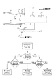
- the device includes three ampere input sockets 41, Volt 42 and Commun 43 arranged on an upper side of the device, and a test lead 44, connected electrically through a connection end 45 to the Ampere 41 input socket or Volt input socket 42, depending on the quantity to be measured.
- the test lead 44 is electrically connected by a measurement end opposite its end of connection to a measurement probe or to a point on which we want to make a measurement, for example a point of a electrical circuit.
- a reference cord 46 electrically conductor, is electrically connected at one end to the common input socket 43, and by one end opposite to a reference point, for example the mass of the electrical circuit on which we want to measure.
- Family 21 touch zones, on / off 30, general settings 31, menu F1 to F5, functional 32 and display content management 33 are all contactors, for example buttons pushbuttons for positioning relays electromechanical or static associated with them, these relays being carried by an electronic card.
- the activation means 22 include a microprocessor 23 receiving commands from touch zones and an electronic switching circuit 24 comprising static and electromechanical relays, connecting the input sockets 41 to 43 to the means of measure 15. Configuration of the switching circuit electronics 24 is controlled by microprocessor 23 in based on commands from touch zones.
- Each push button sends a microprocessor control 50.
- the light indicators 34 are controlled by the microprocessor 50, which turns them on and off function of control signals received from the means activation 22.
- the microprocessor 50 also ensures the management display screen 10 and the automatic choice of measurement range according to the input signal.
- the apparatus includes means for detecting the connection end 45 of the connection cord measures 44 at the Ampere 41 input socket or at the socket input Volt 42.
- the Ampere and Volt input sockets 41 and 42 each include two half-sockets electrically isolated from each other, respectively the Ampère 411 and Volts 421 half-sockets.
- connection end 45 of the test lead is fitted with plug 48 fitting the two half-sockets Ampere 411 short-circuited when the end of connection 45 of the cord is connected to the socket input Ampere 41, and putting the two half-sockets Volt 421 shorted when connection end 45 of the cord is connected to the input socket Volt 42
- Detection means detect short-circuiting two Ampère 411 or Volt 412 half-sockets comparing the potentials of the half-sockets of the same socket.
- microprocessor 23 tests whether the cord 44 is present in the Ampere input socket 41 or in the Volt 42 inlet socket.
- the microprocessor 23 activates the measuring means corresponding.
- the device emits an alarm audible and / or visual.
- the microprocessor 23 tests periodically if there is still a match between the position of the test lead in the sockets and the selected quantity to be measured.
- the current measurement means will only be activated only if the test lead 44 is connected to the input socket Ampere 41, and if the size selected is the current.
- the means of voltage measurement will only be activated if the power cord measure 44 is connected to the input socket Volt 42, and if the quantity selected is the voltage.
- This device functionality allows get rid of a common handling error on a multimeter, which consists of confusing voltage and current and to select the current using the device selection 20 while the appliance is connected to a source of tension. We risk damaging it seriously.
- One of the two half-sockets 411 of the socket input Ampere 41 is electrically connected to the socket Common input 43 through an F1 main fuse and a secondary fuse F2 in series.
- the main fuse F1 is a strong fuse capacity, cutting to 1000 Volts and 11 Amps. This fuse is expensive and difficult to supply.
- the secondary fuse F2 is a current fuse, inexpensive, cutting to about 10 amps and a voltage less than half the voltage at which the main fuse F1 cuts, for example 250 Volts.
- This secondary fuse F2 more sensitive than the main fuse, protects it because it will be destroyed before the main fuse F1 in case of bad handling of the device.
- This mishandling can for example consist in connecting the test lead 44 to the socket 41 amp input, and connect the test lead to an important source of tension. Fuse F2 will destroyed, and the F1 fuse will be preserved.
- the device only has one single Ampere input socket, which means that only one set of fuses and save space.
- the device offers advantages, while preserving the visual aspect to which the users are used to it.
- the touch zones form in effect a circle reminiscent of the mechanical selector traditional rotary, and select the family of quantity to be measured, such as the selector rotary.
- the apparatus of the invention has the advantage of being able to be completely controlled at distance, which allows it to be calibrated automatic, without mechanical actuator.
- the structure of the device also allows perform automatic polls, which consist of cyclically measure different quantities in passing from one to the other after a time delay.
- the device allows a direct and quick access to the main functions, which this is not the case with the devices of the prior art.
- Figure 5 shows part of the facade of a prior art measuring device equipped with a rotary mechanical selector 70 and two buttons selection 71 and 72.
- the selector 70 can adopt twelve positions numbered from 1 to 12 in Figure 5, accessible at from position 1 by turning the selector in a predetermined direction, represented by an arrow. The device is stopped when the selector is in position 1.
- Table 1 compares the number of shares necessary, in the case of the apparatus of the invention and in the case of the apparatus of FIG. 5, for select a measured quantity and adjust the main parameters associated with this quantity, such as for example the type of current (alternating or direct) for intensity measurements or measurement range.
- a action is to press a touch area in the case of the invention and turn the selector one position or to press a button in the case of the device of figure 5.
- Another advantage of the device is that it does not includes no moving parts such as a selector rotary or friction parts, and therefore it wears out very slowly. Its reliability is therefore very high.
- the use of the selection device does not requires only one hand, as it is enough to press touch zones with a finger. This mode of operation is quick and easy.
- the device is preferably portable, but can be fixed. Its dimensions are comparable to those of a portable multimeter conventionally used to control circuits electric and equipped with a rotary mechanical selector.
Landscapes
- Physics & Mathematics (AREA)
- General Physics & Mathematics (AREA)
- Measuring Instrument Details And Bridges, And Automatic Balancing Devices (AREA)
Priority Applications (2)
| Application Number | Priority Date | Filing Date | Title |
|---|---|---|---|
| EP02291817A EP1385012A1 (de) | 2002-07-18 | 2002-07-18 | Multimeter mit berührungsempfindlicher Auswahlvorrichtung |
| US10/620,799 US6927564B2 (en) | 2002-07-18 | 2003-07-17 | Multimeter instrument with touch-sensitive selection device |
Applications Claiming Priority (1)
| Application Number | Priority Date | Filing Date | Title |
|---|---|---|---|
| EP02291817A EP1385012A1 (de) | 2002-07-18 | 2002-07-18 | Multimeter mit berührungsempfindlicher Auswahlvorrichtung |
Publications (1)
| Publication Number | Publication Date |
|---|---|
| EP1385012A1 true EP1385012A1 (de) | 2004-01-28 |
Family
ID=29797332
Family Applications (1)
| Application Number | Title | Priority Date | Filing Date |
|---|---|---|---|
| EP02291817A Ceased EP1385012A1 (de) | 2002-07-18 | 2002-07-18 | Multimeter mit berührungsempfindlicher Auswahlvorrichtung |
Country Status (2)
| Country | Link |
|---|---|
| US (1) | US6927564B2 (de) |
| EP (1) | EP1385012A1 (de) |
Cited By (2)
| Publication number | Priority date | Publication date | Assignee | Title |
|---|---|---|---|---|
| ES2390300A1 (es) * | 2011-03-07 | 2012-11-08 | Aigües Ter Llobregat (Atll) | Equipo medidor de tensión intermembranas para pilas de electrodiálisis reversible. |
| CN111929635A (zh) * | 2020-09-14 | 2020-11-13 | 杭州海兴电力科技股份有限公司 | 电能表自热影响补偿系统及方法 |
Families Citing this family (12)
| Publication number | Priority date | Publication date | Assignee | Title |
|---|---|---|---|---|
| DE102004054585A1 (de) * | 2004-11-11 | 2006-07-20 | Siemens Ag | Multimodales Gerät mit einfachem Moduswechsel |
| AT10497U3 (de) * | 2008-12-30 | 2010-01-15 | Ditest Fahrzeugdiagnose Gmbh | Multimeter mit elektronischem überstromschutz |
| US20110316523A1 (en) * | 2010-06-29 | 2011-12-29 | Hsin-Chen Ko | Avometer |
| US9377485B2 (en) | 2013-03-15 | 2016-06-28 | Fluke Corporation | Handheld measurement system with selectable options |
| CN105261194A (zh) * | 2015-11-23 | 2016-01-20 | 国网重庆市电力公司电力科学研究院 | 一种具有存储功能的测量仪 |
| CN105261195A (zh) * | 2015-11-23 | 2016-01-20 | 国网重庆市电力公司电力科学研究院 | 一种具有远程指导现场操作的测量仪 |
| USD861717S1 (en) | 2017-09-05 | 2019-10-01 | Snap-On Incorporated | Multiprobe circuit tester with animated graphical user interface |
| USD876455S1 (en) | 2017-10-02 | 2020-02-25 | Snap-On Incorporated | Multiprobe circuit tester display with graphical user interface |
| CN109765413A (zh) * | 2018-12-05 | 2019-05-17 | 柏焕玉 | 一种新能源汽车电路检测用万用表 |
| USD983057S1 (en) * | 2021-07-05 | 2023-04-11 | Hunan Lianke Technology Co., Ltd | Car diagnostic scan tool |
| USD974200S1 (en) * | 2021-09-02 | 2023-01-03 | Plusivo Limited | Multimeter |
| JP7709623B2 (ja) | 2022-03-16 | 2025-07-16 | フルークコーポレイション | 電気測定ツールのための分割絶縁入力ポスト |
Citations (5)
| Publication number | Priority date | Publication date | Assignee | Title |
|---|---|---|---|---|
| US4825392A (en) * | 1986-08-20 | 1989-04-25 | Freeman Mark S | Dual function DMM display |
| US4949274A (en) * | 1987-05-22 | 1990-08-14 | Omega Engineering, Inc. | Test meters |
| JPH0560798A (ja) * | 1991-09-02 | 1993-03-12 | Hioki Ee Corp | デジタルマルチメータ |
| US6271654B1 (en) * | 1999-11-17 | 2001-08-07 | Lee-Fei Chen | Multifunctional meter with dual input channels |
| US6281673B1 (en) * | 1999-03-09 | 2001-08-28 | Fluke Corporation | Low error, switchable measurement lead detect circuit |
Family Cites Families (5)
| Publication number | Priority date | Publication date | Assignee | Title |
|---|---|---|---|---|
| US4821030A (en) * | 1986-12-19 | 1989-04-11 | Tektronix, Inc. | Touchscreen feedback system |
| DE4027804A1 (de) * | 1990-09-01 | 1992-03-05 | Abb Patent Gmbh | Messverfahren zum messen unterschiedlicher messgroessen und multimeter zur durchfuehrung des verfahrens |
| US5821742A (en) * | 1994-11-30 | 1998-10-13 | Utility Test Equipment Company | Computerized solid state energy meter test system and method of testing |
| US6064372A (en) * | 1996-11-27 | 2000-05-16 | Fluke Corporation | Touchscreen display system for a test instrument |
| US6515484B1 (en) * | 2000-10-31 | 2003-02-04 | Associated Research, Inc. | Electrical test instrument having an improved operator interface |
-
2002
- 2002-07-18 EP EP02291817A patent/EP1385012A1/de not_active Ceased
-
2003
- 2003-07-17 US US10/620,799 patent/US6927564B2/en not_active Expired - Lifetime
Patent Citations (5)
| Publication number | Priority date | Publication date | Assignee | Title |
|---|---|---|---|---|
| US4825392A (en) * | 1986-08-20 | 1989-04-25 | Freeman Mark S | Dual function DMM display |
| US4949274A (en) * | 1987-05-22 | 1990-08-14 | Omega Engineering, Inc. | Test meters |
| JPH0560798A (ja) * | 1991-09-02 | 1993-03-12 | Hioki Ee Corp | デジタルマルチメータ |
| US6281673B1 (en) * | 1999-03-09 | 2001-08-28 | Fluke Corporation | Low error, switchable measurement lead detect circuit |
| US6271654B1 (en) * | 1999-11-17 | 2001-08-07 | Lee-Fei Chen | Multifunctional meter with dual input channels |
Non-Patent Citations (1)
| Title |
|---|
| PATENT ABSTRACTS OF JAPAN vol. 017, no. 369 (P - 1572) 12 July 1993 (1993-07-12) * |
Cited By (2)
| Publication number | Priority date | Publication date | Assignee | Title |
|---|---|---|---|---|
| ES2390300A1 (es) * | 2011-03-07 | 2012-11-08 | Aigües Ter Llobregat (Atll) | Equipo medidor de tensión intermembranas para pilas de electrodiálisis reversible. |
| CN111929635A (zh) * | 2020-09-14 | 2020-11-13 | 杭州海兴电力科技股份有限公司 | 电能表自热影响补偿系统及方法 |
Also Published As
| Publication number | Publication date |
|---|---|
| US6927564B2 (en) | 2005-08-09 |
| US20040130330A1 (en) | 2004-07-08 |
Similar Documents
| Publication | Publication Date | Title |
|---|---|---|
| JP2018503073A (ja) | 診断用回路試験デバイス | |
| FR2522142A1 (fr) | Thermometre clinique electronique | |
| US6927564B2 (en) | Multimeter instrument with touch-sensitive selection device | |
| EP1198715B1 (de) | Gerät und verfahren zur individuellen bestimmung der alterung eines kondensators | |
| EP1042679A1 (de) | Elektronischer überwachungsschaltung für elektrische spannung | |
| CA1221416A (fr) | Ohmmetre pour la mesure de tres faibles resistances electriques | |
| US5227984A (en) | Instrument with continuity capture feature | |
| EP2682972A1 (de) | Vorrichtung zur Erkennung des offenen oder geschlossenen Zustands eines Schalters, und Schutz-Relaisüberwachungsvorrichtung des entsprechenden Transformators | |
| FR2867566A1 (fr) | Agencement d'un instrument de mesure avec une famille de capteurs | |
| FR2544859A1 (fr) | Dispositif autoalimente de commutation sensible a un gradient de temperature | |
| JP2013242251A (ja) | 導通検査装置及び導通検査方法 | |
| EP3552034B1 (de) | Verfahren zur herstellung eines messsensors für einen leistungsschalter | |
| EP0316493B1 (de) | Vorrichtung zur Überwachung der guten elektrischen und/oder mechanischen Funktionierung von Anzeiger-Elementen des elektro-magnetischen Typs | |
| FR2836974A1 (fr) | Dispositif electronique et procede de selection de vitesses pour boite de vitesses automatiques | |
| EP0100807A1 (de) | Messinstrument mit elektrischem Kontakt | |
| KR200240856Y1 (ko) | 릴레이 접점 이상 판단장치 | |
| FR2479500A1 (fr) | Controleur de cablage programmable | |
| CA2355697C (fr) | Dispositif d'acquisition d'etats logiques de multiples capteurs | |
| FR2761154A1 (fr) | Installation de detection et de localisation de fuites de liquides | |
| EP0589797A1 (de) | Schaltsystem mit Selbsttestfunktion | |
| FR2680595A1 (fr) | Dispositif de controle de segment pour afficheur a cristaux liquides, et procede de controle correspondant. | |
| FR2904525A1 (fr) | Dispositif d'evaluation de donnees physiologiques provenant de detecteurs | |
| CN210720542U (zh) | 一种改良万用表 | |
| HK1062713A (en) | Multimeter with touch sensitive selection device | |
| KR101692476B1 (ko) | 레이더부품 점검장치 |
Legal Events
| Date | Code | Title | Description |
|---|---|---|---|
| PUAI | Public reference made under article 153(3) epc to a published international application that has entered the european phase |
Free format text: ORIGINAL CODE: 0009012 |
|
| AK | Designated contracting states |
Kind code of ref document: A1 Designated state(s): AT BE BG CH CY CZ DE DK EE ES FI FR GB GR IE IT LI LU MC NL PT SE SK TR |
|
| AX | Request for extension of the european patent |
Extension state: AL LT LV MK RO SI |
|
| 17P | Request for examination filed |
Effective date: 20040722 |
|
| AKX | Designation fees paid |
Designated state(s): AT BE BG CH CY CZ DE DK EE ES FI FR GB GR IE IT LI LU MC NL PT SE SK TR |
|
| AXX | Extension fees paid |
Extension state: SI Payment date: 20040722 |
|
| REG | Reference to a national code |
Ref country code: HK Ref legal event code: DE Ref document number: 1062713 Country of ref document: HK |
|
| REG | Reference to a national code |
Ref country code: HK Ref legal event code: WD Ref document number: 1062713 Country of ref document: HK |
|
| STAA | Information on the status of an ep patent application or granted ep patent |
Free format text: STATUS: THE APPLICATION HAS BEEN REFUSED |
|
| 18R | Application refused |
Effective date: 20101111 |