EP1385159A1 - Objectif, capteur optique équipé d'un tel objectif et appareil d'enregistrement/lecture optique d'information - Google Patents
Objectif, capteur optique équipé d'un tel objectif et appareil d'enregistrement/lecture optique d'information Download PDFInfo
- Publication number
- EP1385159A1 EP1385159A1 EP03254639A EP03254639A EP1385159A1 EP 1385159 A1 EP1385159 A1 EP 1385159A1 EP 03254639 A EP03254639 A EP 03254639A EP 03254639 A EP03254639 A EP 03254639A EP 1385159 A1 EP1385159 A1 EP 1385159A1
- Authority
- EP
- European Patent Office
- Prior art keywords
- optical
- optical element
- objective lens
- lens unit
- information recording
- Prior art date
- Legal status (The legal status is an assumption and is not a legal conclusion. Google has not performed a legal analysis and makes no representation as to the accuracy of the status listed.)
- Withdrawn
Links
- 230000003287 optical effect Effects 0.000 title claims abstract description 409
- 230000004075 alteration Effects 0.000 claims description 82
- 230000004907 flux Effects 0.000 claims description 28
- 230000008859 change Effects 0.000 claims description 26
- 239000000758 substrate Substances 0.000 claims 2
- 239000004065 semiconductor Substances 0.000 description 18
- 230000000694 effects Effects 0.000 description 14
- 238000004519 manufacturing process Methods 0.000 description 13
- 238000010586 diagram Methods 0.000 description 11
- 238000012937 correction Methods 0.000 description 10
- 239000002184 metal Substances 0.000 description 10
- 230000007423 decrease Effects 0.000 description 9
- 230000001681 protective effect Effects 0.000 description 9
- 238000001746 injection moulding Methods 0.000 description 8
- 206010010071 Coma Diseases 0.000 description 6
- 201000009310 astigmatism Diseases 0.000 description 5
- 238000005516 engineering process Methods 0.000 description 5
- 239000000463 material Substances 0.000 description 5
- 238000005520 cutting process Methods 0.000 description 4
- 239000011521 glass Substances 0.000 description 4
- 238000000034 method Methods 0.000 description 4
- 238000013461 design Methods 0.000 description 3
- 238000001514 detection method Methods 0.000 description 3
- 229910003460 diamond Inorganic materials 0.000 description 3
- 239000010432 diamond Substances 0.000 description 3
- 239000006185 dispersion Substances 0.000 description 3
- 238000005452 bending Methods 0.000 description 2
- 238000000748 compression moulding Methods 0.000 description 2
- 238000010894 electron beam technology Methods 0.000 description 2
- 238000012545 processing Methods 0.000 description 2
- 239000007787 solid Substances 0.000 description 2
- 230000009471 action Effects 0.000 description 1
- 230000015572 biosynthetic process Effects 0.000 description 1
- 230000003247 decreasing effect Effects 0.000 description 1
- 238000011161 development Methods 0.000 description 1
- 230000018109 developmental process Effects 0.000 description 1
- 238000007516 diamond turning Methods 0.000 description 1
- 238000005530 etching Methods 0.000 description 1
- 230000005484 gravity Effects 0.000 description 1
- 238000002347 injection Methods 0.000 description 1
- 239000007924 injection Substances 0.000 description 1
- 238000009434 installation Methods 0.000 description 1
- 238000000465 moulding Methods 0.000 description 1
- 238000010137 moulding (plastic) Methods 0.000 description 1
- 230000010355 oscillation Effects 0.000 description 1
- 230000002093 peripheral effect Effects 0.000 description 1
- 238000000206 photolithography Methods 0.000 description 1
- 238000002360 preparation method Methods 0.000 description 1
- 238000003860 storage Methods 0.000 description 1
Images


Classifications
-
- G—PHYSICS
- G11—INFORMATION STORAGE
- G11B—INFORMATION STORAGE BASED ON RELATIVE MOVEMENT BETWEEN RECORD CARRIER AND TRANSDUCER
- G11B7/00—Recording or reproducing by optical means, e.g. recording using a thermal beam of optical radiation by modifying optical properties or the physical structure, reproducing using an optical beam at lower power by sensing optical properties; Record carriers therefor
- G11B7/12—Heads, e.g. forming of the optical beam spot or modulation of the optical beam
- G11B7/135—Means for guiding the beam from the source to the record carrier or from the record carrier to the detector
- G11B7/1353—Diffractive elements, e.g. holograms or gratings
-
- G—PHYSICS
- G02—OPTICS
- G02B—OPTICAL ELEMENTS, SYSTEMS OR APPARATUS
- G02B13/00—Optical objectives specially designed for the purposes specified below
-
- G—PHYSICS
- G11—INFORMATION STORAGE
- G11B—INFORMATION STORAGE BASED ON RELATIVE MOVEMENT BETWEEN RECORD CARRIER AND TRANSDUCER
- G11B7/00—Recording or reproducing by optical means, e.g. recording using a thermal beam of optical radiation by modifying optical properties or the physical structure, reproducing using an optical beam at lower power by sensing optical properties; Record carriers therefor
- G11B7/12—Heads, e.g. forming of the optical beam spot or modulation of the optical beam
- G11B7/125—Optical beam sources therefor, e.g. laser control circuitry specially adapted for optical storage devices; Modulators, e.g. means for controlling the size or intensity of optical spots or optical traces
- G11B7/127—Lasers; Multiple laser arrays
- G11B7/1275—Two or more lasers having different wavelengths
-
- G—PHYSICS
- G11—INFORMATION STORAGE
- G11B—INFORMATION STORAGE BASED ON RELATIVE MOVEMENT BETWEEN RECORD CARRIER AND TRANSDUCER
- G11B7/00—Recording or reproducing by optical means, e.g. recording using a thermal beam of optical radiation by modifying optical properties or the physical structure, reproducing using an optical beam at lower power by sensing optical properties; Record carriers therefor
- G11B7/12—Heads, e.g. forming of the optical beam spot or modulation of the optical beam
- G11B7/135—Means for guiding the beam from the source to the record carrier or from the record carrier to the detector
- G11B7/1372—Lenses
- G11B7/1374—Objective lenses
-
- G—PHYSICS
- G11—INFORMATION STORAGE
- G11B—INFORMATION STORAGE BASED ON RELATIVE MOVEMENT BETWEEN RECORD CARRIER AND TRANSDUCER
- G11B7/00—Recording or reproducing by optical means, e.g. recording using a thermal beam of optical radiation by modifying optical properties or the physical structure, reproducing using an optical beam at lower power by sensing optical properties; Record carriers therefor
- G11B7/12—Heads, e.g. forming of the optical beam spot or modulation of the optical beam
- G11B7/135—Means for guiding the beam from the source to the record carrier or from the record carrier to the detector
- G11B7/1392—Means for controlling the beam wavefront, e.g. for correction of aberration
- G11B7/13922—Means for controlling the beam wavefront, e.g. for correction of aberration passive
-
- G—PHYSICS
- G11—INFORMATION STORAGE
- G11B—INFORMATION STORAGE BASED ON RELATIVE MOVEMENT BETWEEN RECORD CARRIER AND TRANSDUCER
- G11B7/00—Recording or reproducing by optical means, e.g. recording using a thermal beam of optical radiation by modifying optical properties or the physical structure, reproducing using an optical beam at lower power by sensing optical properties; Record carriers therefor
- G11B2007/0003—Recording, reproducing or erasing systems characterised by the structure or type of the carrier
- G11B2007/0006—Recording, reproducing or erasing systems characterised by the structure or type of the carrier adapted for scanning different types of carrier, e.g. CD & DVD
Definitions
- the present invention relates to an objective lens unit used for converging a light flux on an information recording surface of an optical information recording medium in an optical pickup device, the optical pickup device equipped with the objective lens unit and to an optical information recording apparatus.
- a plastic lens has mainly be used as an objective lens that is used in an optical pickup device for recording/reproducing for optical information recording media such as CD, MO and DVD.
- the specific gravity of the plastic lens is low, compared with a glass lens, the load on an actuator that drives the objective lens can be reduced, which makes it possible for the objective lens to follow at high speed.
- a plastic lens manufactured through injection molding of plastic materials in a metal mold can be manufactured on a mass-production basis at higher accuracy, by manufacturing a metal mold in a desired shape to be highly accurate. It is therefore possible to attain a high-performance and low-cost lens.
- an optical pickup device for a new high density optical disk employing a violet semiconductor laser light source having a wavelength of about 400 nm and an objective lens wherein the numerical aperture on the part of an image (NA) is raised up to the level of about 0.85.
- NA numerical aperture on the part of an image
- high density DVD information of 20 - 30 GB per one surface can be recorded on an optical disk having a diameter of 12 cm that is in the same size as in DVD (numerical aperture of 0.6, a light source wavelength of 650 nm and storage capacity of 4.7 GB).
- optical pickup device for the high density DVD of this kind it is required to record and reproduce three types of optical disks each having a different standard (recording density) such as high density DVD, DVD and CD, on a compatible basis.
- Optical pickup devices having interchangeability for plural types of optical information recording media (for example, CD and DVD) have been developed, and a part of them are on the market.
- Optical pickup apparatuses of this kind there is used a laser which has a different wavelength depending on a type of the optical information recording medium. Therefore, in each of these many optical pickup apparatuses, there is formed, on an optical surface of an objective lens, a ring-shaped structure that is divided into plural ring-shaped zones which cause a prescribed optical path difference for incident light, so that a single objective lens may have interchangeability for plural types of optical information recording media (these technologies are disclosed in TOKKAI Nos. 2000-81566, 2001-195769 and 2001-51192).
- energy density (power) of a laser beam is raised, for recording data, by increasing an electric current that flows through a laser oscillator, and energy density of a laser beam is lowered, for reproducing data, by decreasing an electric current that flows through a laser oscillator.
- chromatic aberration When a wavelength of the laser becomes longer, a position of a beam spot formed on an optical axis is moved by dispersion of a lens to be farther from the objective lens ("chromatic aberration"). Namely, the position of the beam spot is shifted out of an information recording surface of an optical disk, and there is the possibility of occurrence of errors when writing data on the optical disk.
- a violet laser with a wavelength of about 400 nm is used as a light source, and an amount of fluctuation of a wavelength caused by mode-hop is several nanometers. Therefore, chromatic aberration caused by mode-hop turns out to be great, compared with an optical pickup device for CD use (light source wavelength: about 780 nm) and an optical pickup device for DVD use (light source wavelength: about 650 nm), thus, the chromatic aberration needs to be corrected.
- TOKKAIHEI No. 6-242373 discloses an objective lens wherein a ring-shaped structure that is divided into plural ring-shaped zones which cause a prescribed optical path difference for incident light is formed on an optical surface of the objective lens.
- optical pickup device is exposed to changes of temperatures caused by fluctuations of atmospheric temperatures at the location of installation and by generation of heat resulting from operations of the device.
- a wavelength of a laser beam emitted from a laser oscillator generally grows greater.
- plastic has characteristics that the refractive index of the plastic becomes smaller when its temperature rises.
- a form of a plastic lens is easily changed because a coefficient of thermal expansion of plastic is greater than that of glass.
- temperature characteristic aberration spherical aberration
- TOKKAIHEI No. 11-337818 discloses an objective lens wherein a ring-shaped structure that is divided into plural ring-shaped zones which cause a prescribed optical path difference for incident light is formed on an optical surface of the objective lens.
- a curvature on the optical surface (the optical surface closer to the optical information recording medium, in particular) of the objective lens is greater because numerical aperture NA on the part of an image of the objective lens is set to about 0.85.
- NA numerical aperture
- a ring-shaped structure is provided on the optical surface having this great curvature for making the objective lens to have interchangeability for plural types of optical information recording media, and/or for correcting chromatic aberration, and/or for correcting temperature characteristic aberration, a pitch of the ring-shaped structure becomes extremely small (about several microns).
- a metal mold used for injection molding for a plastic lens is manufactured by a method for cutting with a diamond cutting tool with a microscopic diameter called SPDT (Single Point Diamond Turning).
- SPDT Single Point Diamond Turning
- phase inconformity portion generated when a shape of a tip of the diamond cutting tool is transferred onto the metal mold, when forming, on the optical surface, a fine form such as a ring-shaped structure having a pitch of several microns.
- An object of the invention is to provide an objective lens unit for optical pickup use wherein plastic is used as a material, a high numerical aperture in the case of using a light source having a short wavelength, correction of chromatic aberration and of temperature characteristic aberration, and recording/reproducing for plural types of optical information recording media are possible, and manufacture is easy and cost is low and an efficiency of utilization of a laser beam is high, an optical pickup device equipped with the aforesaid objective lens unit and an optical information recording and reproducing apparatus.
- the invention described in Item 1 for solving the problems stated above is represented by objective lens units 1 and 2 each being used for converging light fluxes (laser) L1 - L3 on information recording surfaces M1r - M3r respectively of optical information recording media (high density DVD) M1, (DVD) M2 and (CD) M3, respectively in optical pickup devices 3 and 4, as shown, for example, in Figs. 1 - 4 and Fig. 8.
- Each of the objective lens units is provided with first optical element B arranged to face the optical information recording media M1 - M3 and with second optical element A that is arranged to face toward light sources (semiconductor laser oscillator) LD1 - LD3 of the first optical element B, and is provided, on at least one optical surface thereof, with a ring-shaped structure which is formed so that neighboring rings among divided plural rings may cause a prescribed optical path difference for incident light, and the first optical element B is provided with optical functional portion B1 and flange portion B2 formed on the periphery of the optical functional portion B1, while, the second optical element A is provided with optical functional portion A1 and flange portion A2 formed on the periphery of the optical functional portion A1, and it is characterized that the flange portion B2 of the first optical element B and the flange portion A2 of the second optical element A are formed so that the first optical element B and the second optical element A may be fixed at the prescribed relative position.
- the objective lens mentioned above means, in a narrow sense, a lens which is arranged at the position closest to an optical information recording medium to face it under the condition that the optical information recording medium is loaded in the optical pickup device, and it means, in a broad sense, a lens which can be operated by an actuator together with the aforesaid lens at least in the direction of its optical axis. Therefore, in the present specification, a numerical aperture of an objective lens closer to an image (closer to the optical information recording medium) means a numerical aperture of the lens surface positioned to be closest to the optical information recording medium on the objective lens.
- a necessary (and prescribed) numerical aperture means a numerical aperture stipulated by the standard for each optical information recording medium, or, a numerical aperture of an objective lens having a diffraction limit performance which can obtain a spot diameter necessary to record or reproduce information depending on a wavelength of a light source to be used, for each optical information recording medium.
- the aforementioned recording of information means recording of information on an information recording surface of the optical information recording medium.
- Reproduction of information mentioned in the present specification means reproduction of information recorded on the information recording surface of the optical information recording medium.
- the objective lens of the invention may be either one used for conducting only recording or reproducing, or one used for conducting both recording and reproducing. Or, it may either be one that is used to conduct recording for a certain optical information recording medium and to conduct reproducing for another optical information recording medium, or it may further be one that is used to conduct recording or reproducing for a certain optical information recording medium and to conduct both recording and reproducing for another optical information recording medium.
- reproducing mentioned in this case includes only reading of information.
- the first optical element arranged to face an optical information recording medium and the second optical element that is provided, on at least one optical surface thereof, with a ring-shaped structure which is formed so that neighboring rings among divided plural rings may cause a prescribed optical path difference for incident light
- the objective lens unit prefferably has interchangeability for plural types of optical information recording media, to correct chromatic aberration and to correct temperature characteristic aberration, by utilizing an aberration correction function for the ring-shaped structure of the second optical element.
- the ring-shaped structure By forming a ring-shaped structure on the second optical element on which the curvature of the optical surface is relatively small, the ring-shaped structure can be formed highly accurately, because a pitch of the ring-shaped structure that realizes an aberration correction function is great.
- the aberration mentioned here means chromatic aberration, temperature characteristic aberration and a change of spherical aberration that is caused when a thickness of a transparent base board of the optical information recording medium is changed.
- the flange portion of the first optical element and the flange portion of the second optical element are formed so that the first optical element and the second optical element may be fixed at the prescribed relative position, relative positioning for the first optical element and the second optical element can be realized accurately and easily. It is therefore possible to combine the first optical element and the second optical element and thereby to assemble an objective lens unit accurately and easily, after forming the first optical element and the second optical element respectively.
- each of the first optical element B and the second optical element A is a plastic lens, in each of the objective lens units 1 and 2 described in Item 1.
- the invention described in Item 3 is characterized in that
- the curvature of the optical surface on which the ring-shaped structure of the second optical element is formed is small, it is possible to secure the larger pitch of the ring-shaped structure, compared with an occasion where such ring-shaped structure is formed on the optical surface of the first optical element where the curvature tends to be small, thus, it is possible to keep a decline of the efficiency of utilization of a laser beam resulting from a manufacture error in the shape of the ring-shaped structure to be small. Further, by making paraxial power of the second optical element to be small, a distance (working distance) between the objective lens and the optical information recording medium can be secured to be large.
- the invention described in Item 4 is characterized in that adjoining rings in the ring-shaped structure are formed to be displaced each other in the optical axis direction to cause the prescribed optical path difference in each of the objective lens units 1 and 2 described in either one of Items 1 - 3.
- the invention described in Item 5 is characterized in that the ring-shaped structure is a diffraction structure having a function to diffract incident light in each of the objective lens units 1 and 2 described in Item 4.
- the optical surface (diffractive surface) on which the diffraction structure is formed means a surface of the optical element, for example, a surface of the lens on which a relief is provided so that the surface may have the function to diffract an incident light flux, and when there exist an area where diffraction is caused and an area where diffraction is not caused on the same optical surface, the aforesaid optical surface means an area where diffraction is caused. Further, a diffraction structure or a diffraction pattern means this area where diffraction is caused.
- a sawtoothed form or a step-like form for each ring-shaped structure which is observed when substantially concentric rings are formed around the center of an optical axis on the surface of the optical element, for example, and when the section of the concentric rings is viewed on a plane including the optical axis, and these forms are included in the form of the relief.
- diffracted lights of an infinite number of orders such as zero-order diffracted light, ⁇ first-order diffracted light, ⁇ second-order diffracted light, ... are generated from the optical surface (diffractive surface) on which a diffractive structure is formed, in general, it is possible to set a form of the relief by making diffraction efficiency of the specific order to be higher than that of other order or by making diffraction efficiency of one specific order (for example, + first-order diffracted light) to be almost 100% according to circumstances, in the case, for example, of the diffractive surface having the relief whose meridional section is serrated as stated above.
- a diffractive structure is optimized by wavelength ⁇ B and by the diffraction order n
- a form of a diffractive structure relievef
- the invention described in Item 6 is characterized in that the ring-shaped structure corrects chromatic aberration generated on at least the first optical element B in each of the objective lens units 1 and 2 described in either one of Items 1 - 5.
- the invention described in Item 7 is characterized in that the wavelength to be used is 500 nm or less in each of the objective lens units 1 and 2 described in Item 6.
- the invention described in Item 8 is characterized in that the first optical element B is a plastic lens and the aforesaid ring-shaped structure corrects spherical aberration caused by a change of the refractive index of the first optical element B, in each of the objective lens units 1 and 2 described in either one of Items 1 - 5.
- the change of the refractive index is caused by temperature fluctuations of the first optical element.
- the invention described in Item 9 is characterized in that the numerical aperture on the image side is 0.75 or more in each of the objective lens units 1 and 2 described in Item 8.
- the invention described in Item 10 is characterized in that a thickness of a transparent base board for protecting the information recording surfaces M1r - M3r and a wavelength of light used for recording and/or reproducing of information are used to converge light fluxes (laser) L1 - L3 on information recording surfaces M1r - M3r of the plural types of optical information recording media (high density DVD) M1, (DVD) M2 and (CD) M3 each being different from others, in each of the objective lens units 1 and 2 and the ring-shaped structure corrects spherical aberration caused by a change of the thickness of the transparent base board of each of the information recording media M1 - M3 and/or spherical aberration caused by a change of a wavelength used for recording and/or reproducing of information for each of the information recording media M1 - M3.
- the transparent base board means an optically transparent and parallel flat plate which is formed on the information recording surface to be closer to a plane of incidence for the light flux on the information recording surface, to protect the information recording surface of the optical information recording medium (optical disk), while, the thickness of the transparent base board means a thickness of the parallel flat plate.
- a light flux emitted from the light source is converged by an objective lens on the information recording surface of the optical information recording medium (optical disk) through the transparent base board.
- high density DVD includes those having a transparent base board having another thickness and those wherein a thickness of the transparent base board is zero, namely, those having no transparent base board, in addition to an optical information recording medium having 0.1 mm-thick transparent base board given as an example.
- the invention described in Item 11 is characterized in that 0.8 ⁇ P1 • T1 ⁇ 1.8 is satisfied when P1 (mm -1 ) represents paraxial power of the first optical element B and T1 (mm) represents a thickness on the optical axis of the first optical element B, in each of the objective lens units 1 and 2 described in either one of Items 1 - 10.
- the third-order spherical aberration component in the case of evaluating image height characteristics with wavefront aberration is not too great, and fifth-order coma component is not too great, and coma difference is not too great.
- sufficient working distance can be secured, and a volume of the first optical element is not too great, thus, load on an actuator can be lightened.
- the invention described in Item 12 is characterized in that the first optical element B is a dioptric lens (refractive lens) in each of the objective lens units 1 and 2 described in either one of Items 1 - 11.
- the dioptric lens in this case means an optical element whose refraction function only is used for changing the direction of a ray of light of incidence, and an optical element (for example, an optical element having a diffractive function) having, on the optical surface, the ring-shaped structure divided into plural rings is not included in the dioptric lens in the present specification.
- the invention described in Item 13 is characterized in that the ring-shaped structure is formed on the aspheric surface, in each of the objective lens units 1 and 2 described in either one of Items 1 - 12.
- the invention described in Item 14 is characterized in that the flange portion B2 of the first optical element B and the flange portion A2 of the second optical element A are formed to be in shapes which make them to be fitted each other and to be in contact with each other, and thereby the first optical element Band the second optical element A can be made to be fixed at the prescribed relative position, in each of the objective lens units 1 and 2 described in either one of Items 1 - 13.
- the same effects as those in the invention described in either one of Items 1 - 13 can be obtained, and the flange portion of the first optical element and the flange portion of the second optical element are formed to be in shapes which make them to be fitted each other and to be in contact with each other, and thereby, the relative positioning of the first optical element and the second optical element can be realized highly accurately and easily. It is therefore possible to combine the first optical element and the second optical element and thereby to assemble an objective lens unit accurately and easily, after forming the first optical element and the second optical element respectively.
- Each of optical pickup devices 1 and 2 representing the invention described in Item 15 is characterized to be provided with the objective lens unit described in either one of Items 1 - 14, as shown, for example, in Fig. 1 - Fig. 4.
- An optical information recording and reproducing apparatus (recording and reproducing apparatus for high density DVD, or high density DVD/DVD/CD-compatible recording and reproducing apparatus) representing the invention described in Item 16 is characterized to be provided with each of optical pickup devices 3 and 4 described in Item 15.
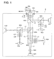
- Fig. 1 is a diagram showing the schematic structure of the objective lens unit of the present embodiment, an optical pickup device equipped with the objective lens unit and of the optical information recording and reproducing apparatus.
- Objective lens unit 1 of the present embodiment is one that is structured to have interchangeability for three types of optical disks (high density DVD, DVD and CD) each having different standard (recording density), and to be capable of recording and/or reproducing for information on these optical disks.
- This objective lens unit is composed of second optical element A whose both sides are made to be aspheric surfaces and a ring-shaped structure is formed on the aspheric surface and of first optical element B whose both sides are made to be aspheric surfaces to be provided with light-converging functions.
- Each of the first optical element B and the second optical element A is made of plastic respectively, and they are provided with optical function portions B1 and A1 as well as with flange portion B2 formed on the periphery of the optical function portion.
- Flange portion B2 of the first optical element B and flange portion A2 of the second optical element A are formed to be in shapes which make them to be fitted with each other and to be in contact with each other, thus, the first optical element B and the second optical element A can be fixed at the prescribed relative position.
- the flange portion of the element can be made long properly in the direction towards the other party on both sides or one side of the element.
- the direction towards the other party in this case means the direction towards the side where these both elements face each other in the optical axis direction, for example, the direction towards the light source side for the first optical element B, and the direction towards the optical information recording medium side for the second optical element A.
- the possibility of change in shape of an optical surface of an optical functional portion which is formed to be solid integrally grows greater, because an amount of shrinking in the optical axis direction and an amount of bending of the flange grow greater in the course of plastic molding.
- the first optical element B is an element having a high numerical aperture, its optical surface is required the higher accuracy in the form, and an influence thereon by shrinking and bending of its flange portion is greater, compared with the second optical element A. It is therefore preferable to have the shape wherein the flange portion A2 of the second optical element A is longer than the flange portion B2 of the first optical element B.
- Optical pickup devices 3 and 4 and an optical information recording and reproducing apparatus are structured so that information is read from an information recording surface by a laser (light flux) with a wavelength of 405 nm emitted from semiconductor laser oscillator LD1, by a laser with a wavelength of 650 nm emitted from semiconductor laser oscillator LD2, and by a laser with a wavelength of 780 nm emitted from semiconductor laser oscillator LD3, respectively for high density DVD, DVD and CD each representing an optical information recording medium.
- a laser light flux
- laser L1 having a wavelength 405 nm emitted from semiconductor laser LD1 passes through beam shaper SH1 to be shaped and beam splitter BS1, then, is made by collimator CL to be parallel light flux, and passes through beam splitters BS4 and BS5 to advance toward objective lens unit 1. Then, a laser beam is converged by the objective lens unit 1 on information recording surface M1r of high density DVD (M1) having a transparent and protective base board.
- the laser L1 modulated by information bit and reflected on the information recording surface M1r passes again through the objective lens unit 1, beam splitters BS4 and BS5 and the collimator CL, to be reflected on beams splitter BS1, and is given astigmatism by cylindrical lens L11, and enters optical detector PD1 after passing through concave lens L12, thus, reading signals of information recorded on high density DVD (M1) are obtained by the use of signals outputted from the optical detector PD1.
- laser L2 having a wavelength of 650 nm emitted from semiconductor laser LD2 passes through beam splitter BS2, then, reflected on the beam splitter BS4, and passes through the beam splitter BS5 to advance toward the objective lens unit 1.
- the objective lens unit 1 converges a laser beam on information recording surface M2r of DVD (M2) having a transparent and protective base board.
- the laser L2 modulated by information bit and reflected on the information recording surface M2r passes again through the objective lens unit 1 and beam splitter B5 to be reflected on beams splitters BS4 and BS3, and is given astigmatism by cylindrical lens L21, and enters optical detector PD2 after passing through concave lens L22, thus, reading signals of information recorded on DVD (M1) are obtained by the use of signals outputted from the optical detector PD2.
- laser L3 having a wavelength of 780 nm emitted from semiconductor laser LD3 passes through beam splitter BS3, then, reflected on the beam splitter BS5 to advance toward the objective lens unit 1.
- the objective lens unit 1 converges a laser beam on information recording surface M3r of CD (M3) having a transparent and protective base board.
- the laser L3 modulated by information bit and reflected on the information recording surface M3r is reflected again by the objective lens unit 1 and beam splitters BS5 and BS3, and is given astigmatism by cylindrical lens L31, and enters optical detector PD3 after passing through concave lens L32, thus, reading signals of information recorded on CD (M3) are obtained by the use of signals outputted from the optical detector PD3.
- each optical information recording medium high density DVD, DVD and CD
- changes in amount of light caused by changes of a spot shape and by positional changes on optical detectors PD1 - PD3 are detected to conduct focusing detection and track detection.
- a two-dimensional actuator moves the objective lens unit 1 so that lasers L1 - L3 emitted respectively from semiconductor laser oscillators LD1 - LD3 may form images respectively on information recording surfaces M1r - Mr3 of optical information recording media (high density DVD, DVD and CD), and lasers L1 - L3 emitted respectively from semiconductor laser oscillators LD1 - LD3 may form images on each prescribed track.
- a ring-shaped diffractive structure is formed on each aspheric surface of both sides (optical surfaces S1 and S2) of optical element A, and its paraxial power is substantially zero.
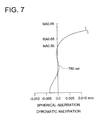
- Optical element B is a plastic lens wherein aberration correction has been made for the transparent and protective base board (thickness: 0.1 mm) of high density DVD (M1), and a design wavelength is 405 nm, a focal length is 2.2 mm and a numerical aperture on the part of a recording medium is 0.85.
- violet laser LD1 representing a light source for high density DVD (M1) is said that its oscillation wavelength is changed by mode-hop by about 1 nm
- the best image position of optical element B evaluated by wavefront aberration is changed by 0.49 ⁇ m when the wavelength of the incident light becomes 406 nm that is longer than the design wavelength by 1 ⁇ m, and thereby, a defocus component is added, and the wavefront aberration is deteriorated to 0.162 ⁇ rms. Accordingly, when the first optical element B is used independently, light-converging power for high density DVD is deteriorated remarkably in the case of mode-hop, which makes it impossible to conduct recording and/or reproducing information stably.
- the objective lens unit 1 in the present embodiment corrects the following changes stated above.
- Objective lens unit 1 of the present embodiment uses 6 th ordered diffracted light generated by the diffractive structure of the second optical element A for high density DVD, 4 th ordered diffracted light generated by the diffractive structure of the second optical element A for DVD, and 3rd ordered diffracted light generated by the diffractive structure of the second optical element A for CD, as light for recording and/or reproducing of information.
- Ring-shaped diffractive structures as shown in Table 2 are formed respectively on both surfaces (the first surface and the second surface in Table 1) of the second optical element A, and they are optimized so that the wavelength may be 415 nm, the diffraction order may be 6 and the diffraction efficiency may be 100% theoretically.
- Optical surfaces S1 and S2 of the first optical element B and optical surfaces S3 and S4 of the second optical element A are formed to be in an aspheric surface form expressed by the following (Numeral 1).
- Z represents an axis in the direction of an optical axis (the direction of travel of light has a positive sign)
- h represents an axis perpendicular to the optical axis (height from the optical axis)
- r represents a paraxial radius of curvature
- ⁇ represents a constant of the cone
- A represents a coefficient of aspheric surface.
- a pitch of the diffractive structure is defined generally by the use of an optical path difference function.
- optical path difference function ⁇ b is expressed by (Numeral 2) with a unit of mm.
- n is a diffraction order of a diffracted ray having the maximum diffraction efficiency among diffracted rays of a light flux having a wavelength of 405 nm generated by the diffractive structure, and in the objective lens unit 1 of the present embodiment, n is 6.
- Table 1 shows lens data for the first optical element B and the first optical element A.
- "-2.6004E - 02" for example, means “-2.6004 x 10 -2 ".
- High density DVD (405 nm, sixth-ordereded diffracted light): 93% DVD (650 nm, fourth-order diffracted light) : 91% CD (780 nm, third-ordered diffracted light): 88%
- the diffractive structure of the second optical element A is arranged so that laser beams which are located to be outside the light fluxes necessary for recording and/or reproducing of DVD and CD do not contribute to formation of beam spots.
- each of light fluxes whose numerical apertures are 0.65 or more in laser L2 entering objective lens unit 1 from red semiconductor laser oscillator LD2 has large spherical aberration, as shown in the spherical aberration diagram in Fig. 5.
- each of light fluxes whose numerical apertures are 0.50 or more in laser L3 entering objective lens unit 1 from red semiconductor laser oscillator LD3 has large spherical aberration, as shown in the spherical aberration diagram in Fig. 6.
- the first optical element B When the first optical element B is used independently for recording/reproducing of high density DVD (M1), light-converging power for high density DVD is remarkably deteriorated in the case of mode-hop of violet semiconductor laser L1, as shown in Fig. 4. However, it is possible to make a change in a position of best image point caused by mode-hop of the violet semiconductor laser to be small.
- the diffractive structure of optical element A has the wavelength characteristic such that spherical aberration changes in the under-corrected direction as wavelength of incident light increases as shown in Fig. 3, it is possible to make both spherical aberration changed in the over-corrected direction on optical element B by a decline of refractive index caused by temperature rise and spherical aberration changed in the under-corrected direction by the shift of oscillated wavelength of a violet semiconductor laser to the long wavelength side caused by temperature rise to be canceled. As a result, it is possible to make a change of spherical aberration of the objective lens unit caused by temperature rise to be small, as shown in Table 5.
- the minimum value of the distance between adjoining diffractive structures is about 20 ⁇ m within an effective diameter of the second optical element A. Therefore, even when a form of the diffractive structure is deviated from a design form by manufacturing errors, a decline of diffraction efficiency caused by light of unwanted order can be made small.
- both the first optical element B and the first optical element A are represented by a plastic lens, and both of them are fitted with each other and are fixed to each other by flanges B2 and A2 formed respectively to be solid integrally with optical functional portions B1 and A1 respectively, and they are driven solidly by an actuator, thus, excellent tracking characteristics are constantly obtained.
- step ⁇ (see Fig. 2) formed on the outermost peripheral portion in an effective diameter of the optical element B has a function of a diaphragm that regulates an incident light flux.
- Fig. 8 shows a variation of optical pickup device 3 in Fig. 1.
- optical pickup device 4 in Fig. 8 on an optical surface of the second optical element A of second optical lens unit 2, there is provided a ring-shaped structure which is divided into plural ring-shaped zones and is formed to be displaced in the optical axis direction each other so that adjoining ring-shaped zones may generate a prescribed optical path difference for incident light.
- objective lens unit 2 has interchangeability for three types of optical disks each having a different standard, in the same way as in objective lens unit 1 of optical pickup device 3 in Fig. 1, and it can conduct recording and/or reproducing of information for the aforementioned optical disks.
- optical pickup device 4 in Fig. 8 all points other than the objective lens unit 2 are the same as those in the optical pickup device 3 in Fig. 1, and detailed explanation will be omitted accordingly.
- the first optical element B only has the aberration correcting functions stated above, but, the aberration correcting functions may also be shared by both the first optical element and the second optical element.
- the objective lens unit 1 is composed of the first optical element B and the second optical element A, but, the objective lens unit in the invention is not limited to be composed of two optical elements, and it can be composed of three or more optical elements, as far as the technical scope of the invention is not exceeded. In that case, it is naturally preferable that adjoining optical elements which face each other are fixed at the prescribed relative position by the flange portions which are respectively formed solidly with optical functional portions respectively, as described in detail in the embodiment mentioned above.
- first optical element and the second optical element are manufactured through injection molding
- these optical elements can be manufactured through various molding methods including an injection compression molding method or a compression molding method, without being limited to the injection molding method.
- the first optical element to be arranged to face an optical information recording medium and the second optical element wherein, a ring-shaped structure that is divided into plural ring-shaped zones and is formed so that adjoining ring-shaped zones generate a prescribed optical path difference for incident light, is formed on at least one optical surface thereof, it is possible to achieve a high numerical aperture of the objective lens unit by setting the curvature of the optical surface of a light source of the first optical element, and to obtain an objective lens unit with a high efficiency of utilization of a laser beam by making an influence of a shade by a step portion of the ring-shaped structure to be small by setting the curvature of the optical surface of the second optical element to be relatively small.
- the objective lens unit it is also possible to make the objective lens unit to have interchangeability for plural types of optical information recording media, to correct chromatic aberration and to correct temperature characteristic aberration, by utilizing aberration correction functions of the ring-shaped structure of the second optical element.
- a pitch of the ring-shaped structure for realizing the aberration correction functions becomes large, which makes it possible to form the ring-shaped structure accurately.
- the aberration of this kind means chromatic aberration, temperature characteristic aberration and the change in spherical aberration generated when a thickness of a transparent base board of the optical information recording medium is changed.
- the flange portion of the first optical element and that of the second optical element are formed to be capable of fixing the first optical element and the second optical element respectively at the prescribed relative position, positioning of the first optical element and the second optical element at the relative position can be conducted accurately and easily. It is therefore possible to assemble the objective lens unit accurately and easily by combining them, after forming the first optical element and the second optical element separately.
- the curvature of the optical surface on which the ring-shaped structure of the second optical element is formed is small, it is possible to secure the larger pitch of the ring-shaped structure, compared with an occasion where such ring-shaped structure is formed on the optical surface of the first optical element where the curvature tends to be small, thus, it is possible to keep a decline of the efficiency of utilization of a laser beam resulting from a manufacture error in the shape of the ring-shaped structure to be small. Further, by making paraxial power of the second optical element to be small, a distance (working distance) between the objective lens and the optical information recording medium can be secured to be large.
- the third-order spherical aberration component in the case of evaluating image height characteristics with wavefront aberration is not too great, and fifth-order coma component is not too great, and coma difference is not too great.
- sufficient working distance can be secured, and a volume of the first optical element is not too great, thus, load on an actuator can be lightened.
- the same effects as those in the invention described in either one of Items 1 - 13 can be obtained, and the flange portion of the first optical element and the flange portion of the second optical element are formed to be in shapes which make them to be fitted each other and to be in contact with each other, and thereby, the relative positioning of the first optical element and the second optical element can be realized highly accurately and easily. It is therefore possible to combine the first optical element and the second optical element and thereby to assemble an objective lens unit accurately and easily, after forming the first optical element and the second optical element respectively.
Landscapes
- Physics & Mathematics (AREA)
- Optics & Photonics (AREA)
- General Physics & Mathematics (AREA)
- Lenses (AREA)
- Optical Head (AREA)
Applications Claiming Priority (2)
| Application Number | Priority Date | Filing Date | Title |
|---|---|---|---|
| JP2002218288A JP2004062971A (ja) | 2002-07-26 | 2002-07-26 | 対物レンズユニット、光ピックアップ装置、及び光学式情報記録再生装置 |
| JP2002218288 | 2002-07-26 |
Publications (1)
| Publication Number | Publication Date |
|---|---|
| EP1385159A1 true EP1385159A1 (fr) | 2004-01-28 |
Family
ID=29997297
Family Applications (1)
| Application Number | Title | Priority Date | Filing Date |
|---|---|---|---|
| EP03254639A Withdrawn EP1385159A1 (fr) | 2002-07-26 | 2003-07-23 | Objectif, capteur optique équipé d'un tel objectif et appareil d'enregistrement/lecture optique d'information |
Country Status (6)
| Country | Link |
|---|---|
| US (1) | US7330420B2 (fr) |
| EP (1) | EP1385159A1 (fr) |
| JP (1) | JP2004062971A (fr) |
| KR (1) | KR20040010334A (fr) |
| CN (1) | CN1278141C (fr) |
| TW (1) | TWI266897B (fr) |
Cited By (3)
| Publication number | Priority date | Publication date | Assignee | Title |
|---|---|---|---|---|
| EP1447798A3 (fr) * | 2003-02-14 | 2004-11-17 | Konica Minolta Holdings, Inc. | Objectif pour appareil de lecture optique, appareil de lecture optique et appareil d'enregistrement et/ou de reproduction d'information |
| EP1612783A3 (fr) * | 2004-07-02 | 2006-06-07 | Konica Minolta Opto, Inc. | Objectif et appareil de lecture optique |
| EP1580737A3 (fr) * | 2004-03-19 | 2006-09-13 | Konica Minolta Opto, Inc. | Système d'objectif d'un capteur optique, capteur optique et dispositif d'enregistrement et/ou lecture optique d'informations |
Families Citing this family (14)
| Publication number | Priority date | Publication date | Assignee | Title |
|---|---|---|---|---|
| JP2004327003A (ja) | 2002-07-26 | 2004-11-18 | Sharp Corp | 光ピックアップ |
| US7460460B2 (en) * | 2004-02-27 | 2008-12-02 | Konica Minolta Opto, Inc. | Objective optical system, optical pickup apparatus and optical information recording and reproducing apparatus |
| JP2005283742A (ja) * | 2004-03-29 | 2005-10-13 | Fuji Photo Film Co Ltd | プラスチック製レンズを用いた光学ユニット |
| JP2005292184A (ja) * | 2004-03-31 | 2005-10-20 | Fuji Photo Film Co Ltd | 光学ユニット |
| JP4600131B2 (ja) * | 2004-04-20 | 2010-12-15 | コニカミノルタオプト株式会社 | 対物レンズ及び光ピックアップ装置 |
| JP2005331858A (ja) * | 2004-05-21 | 2005-12-02 | Fuji Photo Film Co Ltd | 光学ユニット |
| JP4807258B2 (ja) * | 2004-06-03 | 2011-11-02 | コニカミノルタオプト株式会社 | 対物レンズ及び光ピックアップ装置 |
| JP2006085837A (ja) | 2004-09-16 | 2006-03-30 | Konica Minolta Opto Inc | 対物レンズユニット及びこれを用いた光ピックアップ装置 |
| JP4992103B2 (ja) * | 2004-12-02 | 2012-08-08 | コニカミノルタアドバンストレイヤー株式会社 | 対物光学系、光ピックアップ装置及び光情報記録再生装置 |
| WO2007013346A1 (fr) * | 2005-07-28 | 2007-02-01 | Matsushita Electric Industrial Co., Ltd. | Tete optique et dispositif a disque optique |
| US8174952B2 (en) * | 2005-11-21 | 2012-05-08 | Ricoh Company, Ltd. | Light source unit, optical detector unit, optical pickup device, and optical disk device |
| JPWO2008126562A1 (ja) * | 2007-03-28 | 2010-07-22 | コニカミノルタオプト株式会社 | 光ピックアップ装置用の対物光学素子ユニット及び光ピックアップ装置 |
| JP2009016559A (ja) | 2007-07-04 | 2009-01-22 | Ricoh Co Ltd | 半導体集積回路 |
| US7967210B2 (en) * | 2007-11-30 | 2011-06-28 | Symbol Technologies, Inc. | Imaging bar code reader having light emitting diode for generating a field of view |
Citations (7)
| Publication number | Priority date | Publication date | Assignee | Title |
|---|---|---|---|---|
| WO2000041173A1 (fr) * | 1999-01-08 | 2000-07-13 | Asahi Kogaku Kogyo Kabushiki Kaisha | Capteur optique |
| US20010050894A1 (en) * | 2000-04-14 | 2001-12-13 | Asahi Kogaku Kogyo Kabushiki Kaisha | Objective optical system for optical pick-up |
| US20020005996A1 (en) * | 2000-06-06 | 2002-01-17 | Kazuya Kitamura | Objective lens, optical pickup-device equipped with same and assembling method of same |
| US20020036839A1 (en) * | 2000-09-01 | 2002-03-28 | Koichiro Kishima | Optical system, method of producing optical system, and optical pickup |
| EP1199717A2 (fr) * | 2000-10-16 | 2002-04-24 | Konica Corporation | Lentille d'objectif, lentille de couplage, système optique convergent, et dispositif de lecture optique |
| US20020097508A1 (en) * | 2001-01-24 | 2002-07-25 | Konica Corporation | Objective lens for use in optical pickup apparatus and optical pickup apparatus |
| EP1304689A2 (fr) * | 2001-10-12 | 2003-04-23 | Konica Corporation | Lentille d'objectif, élément d'objectif, dispositif de lecture d'objectif et appareil d'enregistrement et/ou de reproduction d'informations muni de ce dispositif |
Family Cites Families (2)
| Publication number | Priority date | Publication date | Assignee | Title |
|---|---|---|---|---|
| JP4610118B2 (ja) * | 2001-03-30 | 2011-01-12 | Hoya株式会社 | 光ヘッド用対物レンズ |
| US6947368B2 (en) * | 2001-12-07 | 2005-09-20 | Koninklijke Philips Electronics N.V. | Duel-layer optical scanner with non-periodic phase structure element of birefringent material for different wavefront aberration compensation of orthogonally polarized radiation beams |
-
2002
- 2002-07-26 JP JP2002218288A patent/JP2004062971A/ja active Pending
-
2003
- 2003-07-23 US US10/624,535 patent/US7330420B2/en not_active Expired - Fee Related
- 2003-07-23 TW TW092120126A patent/TWI266897B/zh active
- 2003-07-23 KR KR1020030050430A patent/KR20040010334A/ko not_active Ceased
- 2003-07-23 CN CNB031330436A patent/CN1278141C/zh not_active Expired - Fee Related
- 2003-07-23 EP EP03254639A patent/EP1385159A1/fr not_active Withdrawn
Patent Citations (7)
| Publication number | Priority date | Publication date | Assignee | Title |
|---|---|---|---|---|
| WO2000041173A1 (fr) * | 1999-01-08 | 2000-07-13 | Asahi Kogaku Kogyo Kabushiki Kaisha | Capteur optique |
| US20010050894A1 (en) * | 2000-04-14 | 2001-12-13 | Asahi Kogaku Kogyo Kabushiki Kaisha | Objective optical system for optical pick-up |
| US20020005996A1 (en) * | 2000-06-06 | 2002-01-17 | Kazuya Kitamura | Objective lens, optical pickup-device equipped with same and assembling method of same |
| US20020036839A1 (en) * | 2000-09-01 | 2002-03-28 | Koichiro Kishima | Optical system, method of producing optical system, and optical pickup |
| EP1199717A2 (fr) * | 2000-10-16 | 2002-04-24 | Konica Corporation | Lentille d'objectif, lentille de couplage, système optique convergent, et dispositif de lecture optique |
| US20020097508A1 (en) * | 2001-01-24 | 2002-07-25 | Konica Corporation | Objective lens for use in optical pickup apparatus and optical pickup apparatus |
| EP1304689A2 (fr) * | 2001-10-12 | 2003-04-23 | Konica Corporation | Lentille d'objectif, élément d'objectif, dispositif de lecture d'objectif et appareil d'enregistrement et/ou de reproduction d'informations muni de ce dispositif |
Cited By (4)
| Publication number | Priority date | Publication date | Assignee | Title |
|---|---|---|---|---|
| EP1447798A3 (fr) * | 2003-02-14 | 2004-11-17 | Konica Minolta Holdings, Inc. | Objectif pour appareil de lecture optique, appareil de lecture optique et appareil d'enregistrement et/ou de reproduction d'information |
| EP1580737A3 (fr) * | 2004-03-19 | 2006-09-13 | Konica Minolta Opto, Inc. | Système d'objectif d'un capteur optique, capteur optique et dispositif d'enregistrement et/ou lecture optique d'informations |
| EP1612783A3 (fr) * | 2004-07-02 | 2006-06-07 | Konica Minolta Opto, Inc. | Objectif et appareil de lecture optique |
| US7664003B2 (en) | 2004-07-02 | 2010-02-16 | Konica Minolta Opto, Inc. | Objective lens and optical pickup apparatus |
Also Published As
| Publication number | Publication date |
|---|---|
| JP2004062971A (ja) | 2004-02-26 |
| CN1278141C (zh) | 2006-10-04 |
| TW200402547A (en) | 2004-02-16 |
| US7330420B2 (en) | 2008-02-12 |
| CN1479117A (zh) | 2004-03-03 |
| US20040114254A1 (en) | 2004-06-17 |
| TWI266897B (en) | 2006-11-21 |
| KR20040010334A (ko) | 2004-01-31 |
Similar Documents
| Publication | Publication Date | Title |
|---|---|---|
| US6865025B2 (en) | Aberration compensating optical element, optical system, optical pickup device, recorder and reproducer | |
| US7330420B2 (en) | Objective lens unit, optical pickup apparatus and optical information recording and reproducing apparatus | |
| US6590717B2 (en) | Optical system for optical disk, optical head unit for optical disk, and optical drive device | |
| KR100452904B1 (ko) | 광픽업장치,광픽업용대물렌즈,광픽업용집광광학계및광디스크장치 | |
| JP3531024B2 (ja) | 光情報記録媒体の記録及び/又は再生用光学系及び対物レンズ | |
| KR100882063B1 (ko) | 대물 렌즈, 광픽업 장치 및 기록 또는 재생 장치 | |
| JP4621964B2 (ja) | 光ピックアップ装置、記録・再生装置及び光ピックアップ装置における球面収差変動の補正方法 | |
| US7221521B2 (en) | Optical pickup lens device and information recording and reproducing device using the same | |
| EP1329881A2 (fr) | Système optique convergent, dispositif de lecture optique, élément de correction d'aberration, et lentille d'objectif | |
| US7855940B2 (en) | Pickup lens with phase compensator and optical pickup apparatus using the same | |
| KR100468855B1 (ko) | 고 개구수를 가지는 하이브리드 렌즈 | |
| US6349083B1 (en) | Near field type optical disk recording reproducing apparatus, optical information recording medium recording reproducing apparatus, pickup apparatus, objective lens | |
| EP0236503B1 (fr) | Dispositif a tete optique | |
| US7120108B2 (en) | Objective lens and optical pickup device | |
| US20060262702A1 (en) | Optical pickup device | |
| US20050068879A1 (en) | Optical scanning device | |
| EP1486961A2 (fr) | Système optique avec élément de correction d'aberration, appareil de lecture optique, appareil d'enregistrement et/ou lecture optique et élément de correction d'aberration | |
| JP2000028917A (ja) | 光情報記録媒体の記録再生用光ピックアップ装置、対物レンズ及び対物レンズの設計方法 | |
| KR101054949B1 (ko) | 광 픽업 및 광 정보 처리 장치 | |
| JP4308204B2 (ja) | 光ヘッド装置 | |
| US7130134B2 (en) | Optical scanning device | |
| JP2004071071A (ja) | 光ピックアップ装置 | |
| JP2005322281A (ja) | 収差補正素子、光ピックアップ用レンズ装置、光ピックアップ装置 | |
| JP4596938B2 (ja) | 光ピックアップ、光情報処理装置 | |
| JP2004198839A (ja) | 光ディスク用の対物レンズ及び対物光学系、並びにこれらを用いた光ヘッド装置 |
Legal Events
| Date | Code | Title | Description |
|---|---|---|---|
| PUAI | Public reference made under article 153(3) epc to a published international application that has entered the european phase |
Free format text: ORIGINAL CODE: 0009012 |
|
| AK | Designated contracting states |
Kind code of ref document: A1 Designated state(s): AT BE BG CH CY CZ DE DK EE ES FI FR GB GR HU IE IT LI LU MC NL PT RO SE SI SK TR |
|
| AX | Request for extension of the european patent |
Extension state: AL LT LV MK |
|
| 17P | Request for examination filed |
Effective date: 20040630 |
|
| AKX | Designation fees paid |
Designated state(s): AT BE BG CH CY CZ DE DK EE ES FI FR GB GR HU IE IT LI LU MC NL PT RO SE SI SK TR |
|
| AXX | Extension fees paid |
Extension state: MK Payment date: 20040630 Extension state: LV Payment date: 20040630 Extension state: LT Payment date: 20040630 Extension state: AL Payment date: 20040630 |
|
| 17Q | First examination report despatched |
Effective date: 20041022 |
|
| RAP1 | Party data changed (applicant data changed or rights of an application transferred) |
Owner name: KONICA MINOLTA OPTO, INC. |
|
| STAA | Information on the status of an ep patent application or granted ep patent |
Free format text: STATUS: THE APPLICATION IS DEEMED TO BE WITHDRAWN |
|
| 18D | Application deemed to be withdrawn |
Effective date: 20080905 |