EP1385340A2 - Méthode de traitement d'image pour un projecteur - Google Patents
Méthode de traitement d'image pour un projecteur Download PDFInfo
- Publication number
- EP1385340A2 EP1385340A2 EP03015500A EP03015500A EP1385340A2 EP 1385340 A2 EP1385340 A2 EP 1385340A2 EP 03015500 A EP03015500 A EP 03015500A EP 03015500 A EP03015500 A EP 03015500A EP 1385340 A2 EP1385340 A2 EP 1385340A2
- Authority
- EP
- European Patent Office
- Prior art keywords
- image
- area
- color
- white
- standard
- Prior art date
- Legal status (The legal status is an assumption and is not a legal conclusion. Google has not performed a legal analysis and makes no representation as to the accuracy of the status listed.)
- Ceased
Links
Images



Classifications
-
- H—ELECTRICITY
- H04—ELECTRIC COMMUNICATION TECHNIQUE
- H04N—PICTORIAL COMMUNICATION, e.g. TELEVISION
- H04N9/00—Details of colour television systems
- H04N9/64—Circuits for processing colour signals
- H04N9/73—Colour balance circuits, e.g. white balance circuits or colour temperature control
-
- H—ELECTRICITY
- H04—ELECTRIC COMMUNICATION TECHNIQUE
- H04N—PICTORIAL COMMUNICATION, e.g. TELEVISION
- H04N5/00—Details of television systems
- H04N5/74—Projection arrangements for image reproduction, e.g. using eidophor
-
- H—ELECTRICITY
- H04—ELECTRIC COMMUNICATION TECHNIQUE
- H04N—PICTORIAL COMMUNICATION, e.g. TELEVISION
- H04N9/00—Details of colour television systems
- H04N9/12—Picture reproducers
- H04N9/31—Projection devices for colour picture display, e.g. using electronic spatial light modulators [ESLM]
- H04N9/3179—Video signal processing therefor
- H04N9/3182—Colour adjustment, e.g. white balance, shading or gamut
Definitions
- the present invention relates to a color adjusting method for a projector, and in particular, to a color adjusting method used if the color of a screen or wall used as an image projecting surface is different from white, to adjust properly the colors of an image displayed on the projecting surface.
- An image projected by a projector such as a liquid crystal projector is displayed on a projecting surface.
- the projecting surface is generally composed of a screen or a wall.
- Such a screen or wall is not necessarily white. Even if it is white when it starts to be used, it may become yellowish or bluish later.
- the image projected on such a screen or wall is displayed in colors relatively different from actual ones. Consequently, a user does not see the displayed image in its original colors. To allow the user to see the image in its original colors, the colors of the projected image must be adjusted.
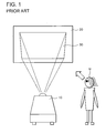
- FIG. 1 is a view showing a conventional color adjusting . method.
- a projector 10 projects an image on a screen 20.
- a user M observes a displayed image 30 on the screen 20. On the basis of the results of the observation, the user adjusts colors by operating the projector 10.
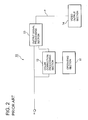
- FIG. 2 is a block diagram showing a configuration of the projector 10.
- the projector 10 includes an operating section 11, a color correction processing section 12, an output signal processing section 13, and a video output section 14.
- the operating section 11 includes key switches and the like and is operated on the basis of the user M's determinations.
- the color correction processing section 12 generates correction data d used to correct an externally supplied video signal in.
- the output signal processing section 13 adds the correction data d to the video signal in to generate a color-adjusted video signal P.
- the video output section 14 is, for example, a three-plate type liquid crystal projector unit that splits white light generated by a light source into primary lights in red, green, and blue. The video output section 14 then modulates the primary lights in accordance with the video signal P. Subsequently, the video output section 14 carries out additive color mixture and then projects the mixed light on the screen 20.
- the user M first observes the color of the displayed image 30. On the basis of the results of the observation, the user operates the operating section 11 to carry out white balance adjustment, color temperature adjustment, and color corrections (adjustment of luminance, hue, or saturation) so that the image assumes desired colors.
- a color adjusting method used for a projector to correct colors of an image on a projecting surface, the image being projected by the projector comprising the steps of: (1) placing a standard image plate in a first area of the projecting surface, (2) projecting white light on the standard image plate, (3) projecting an image on a second area of the projecting surface, and (4) correcting colors of the image in the second area so that the colors are closer to colors of the standard image plate.
- a color adjusting method used for a projector to correct colors of an image on a projecting surface, the image being projected by the projector comprising the steps of: (1) placing a white plate in a first area of the projecting surface, (2) projecting a standard image on the white plate, (3) projecting an image on a second area of the projecting surface, and (4) correcting colors of the image in the second area so that the colors are closer to colors of the standard image.
- a projector that projects an image on a projecting surface
- the projector comprising an image dividing section that forms a first area and a second area in an image to be projected, a video output section that projects, as an image for the first area, white light on a standard image plate on which a standard image has been drawn, while projecting an image for the second area on the projecting surface, an operating section operated by a user, and a color correcting section that corrects the image in the second area on the basis of information inputted to the operating section.
- a projector that projects an image on a projecting surface
- the projector comprising an image dividing section that forms a first area and a second area in an image to be projected, a video output section that projects a standard image on a white plate as an image for the first area, while projecting an image for the second area on the projecting surface, an operating section operated by a user, and a color correcting section that corrects the image in the second area on the basis of information inputted to the operating section.
- FIG. 3 is a schematic view showing a first embodiment of the present invention.
- the first embodiment includes a projector 40, a screen 50, and a standard image plate 60.
- the projector 40 projects an image corresponding to an inputted video signal, on the screen 50.
- the projector 40 divides a display area of the screen 50 into two vertically or horizontally arranged areas. White light is projected in one J of the two areas. An image is projected in the other area K.
- the screen 50 which was white when it started to be used, has become yellowish or bluish owing to secular changes.
- the standard image plate 60 is installed in an area J of the screen 50.
- a standard image is drawn on the standard image plate 60 and is displayed in its correct colors when the projector 40 projects white light on it through a standard white area W.
- the standard image contain all of, for example, white, red, green, blue, and a memory color (for example, flesh color, plant green, or sky blue).
- the projector 40 projects a corrected image in the area K of the screen 50 through a corrected image projecting area C, the corrected image having the same pattern as that of the standard image drawn on the standard image plate 60.
- the user observes the standard image on the area J and the corrected image on the area K of the screen 50. On the basis of the results of the observation, the user operates the projector 40 so that the corrected image has the same colors as those of the standard image.
- FIG. 4 is a block diagram showing a configuration of the projector 40.
- the projector 40 includes an internal image generating section 41, an image switching section 42, an operating section 43, a color correction processing section 44, an image division processing section 45, and a video output section 70.
- the internal image generating section 41 holds, as an internal image, a corrected image projected in the area K of the screen 50.
- the internal image generating section 41 generates a corrected image having the same pattern as that of the standard image drawn on the standard image plate 60.
- the image switching section 42 selectively switches between the image held by the internal image generating section 41 as an internal image and a video signal in corresponding to the user's favorite image, on the basis of the user' s operation.
- the operating section 43 includes key switches and the like and is operated on the basis of the user's determinations.
- the color correction processing section 44 generates correction data d on the basis of an operation performed on the operating section 43 by the user, the correction data d being used to correct the image selected by the internal image generating section 41.
- the image division processing section 45 adds the correction data d to the image selected by the image switching section 42, to generate a color-adjusted corrected image and thus a video signal P.
- the video signal P divides the display area of the screen 50 into the two horizontally arranged areas J and K.
- the video signal P projects the corrected image in the area K, while projecting white light in the area J (standard image plate 60) .
- the video output section 70 includes a three-plate type liquid crystal projector unit, for example.
- the video output section 70 splits white light generated by a light source into primary lights in red, green, and blue. The video output section 70 then modulates each primary light in accordance with the video signal P outputted by the screen division processing section 45. The video output section 70 finally executes additive color mixture to mix the lights and projects the mixed light on the screen 20.
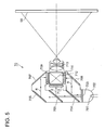
- FIG. 5 is a view showing an example of a configuration of the video output section 70.
- the video output section 70 is a three-plate type liquid crystal projector unit including a lamp 701, a reflector 702, an interference filter 703, dichroic mirrors 704 and 705, mirrors 706, 707, and 708, liquid crystal light valves 709, 710, and 711, a dichroic prism 712, and a projection lens 713.
- the video output section 70 uses the dichroic mirrors 704 and 705 to split white light generated by the lamp 701 into primary lights in red, green, and blue.
- the video output section 70 then modulates each primary light in accordance with the video signal P (the light is transmitted or blocked by the liquid crystal light valves 709, 710, and 711).
- the dichroic prism 712 mixes the lights and the projection lens 713 projects the mixed light on the screen 50.
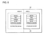
- FIG. 6 is a view showing an example of the standard image on the standard image plate 60 and the corrected image in the area K of the screen 50.
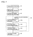
- FIG. 7 is a flow chart illustrating a color adjusting method used for the projector 40. With reference to FIGS. 6 and 7, description will be given of the contents of processing executed in the color adjusting method used in the present embodiment.
- the image division processing section 45 divides the display area of the screen 50 into two horizontally arranged areas J and K (step A1, area dividing process) .
- the standard image plate 60 is installed on the area J of the screen 50.
- the video output section 70 projects white light on the standard image plate 60 (step A2, white light projecting process). Further, the video output section 70 projects a corrected image on the area K of the screen 50, the corrected image having the same pattern as that of the standard image drawn on the standard image plate 60 (step A3, corrected image projecting process).
- the user compares the two images and operates the operating section 43 so that the corrected image on the area K is closer to the standard image on the standard image plate 60 .
- the color correction processing section 44 creates correction data d to correct the video signal in (step A4, corrected data creating process).
- This corrected data creating process comprises at least one of a white adjusting process (step A4a), a color balance adjusting process (step A4b), and a specific color adjusting process (step A4c).
- the white adjusting process (step A4a) comprises paying attention to white parts of the corrected and standard images to make adjustment so that the luminance of the white part of the corrected image is closer to that of the standard image.
- the color balance adjusting process (step A4b) comprises paying attention to the color balance of the entire corrected and standard images to make adjustment so that the color balance of the corrected image is closer to that of the standard image. In this case, at least one of the luminance, hue, and saturation of red, green, and blue in the corrected image is adjusted.
- the specific color adjusting process comprises paying attention to a specific color (for example, a memory color such as flesh color or sky blue) part of each of the corrected and standard images to make adjustment so that the color of the specific color part of the corrected image is closer to that of the standard image.
- the color correction processing section 44 adds the correction data d to the video signal in to adjust the colors of the corrected image displayed on the screen 50 (step A5, color adjusting process).
- the screen division processing section 45 clears the division of the display area of the screen 50.
- the video output section 70 displays, on the screen 50, an image obtained by adjusting the color of the video signal in.
- the standard image plate 60 is installed in the area J of the screen 50 . Then, the standard image on the standard image plate 60 is used as a reference to adjust the color of the corrected image on the area K of the screen 50. Consequently, even if the color of the screen 50 is different from white, the user can adjust the colors of the video signal in by operating the operating section 43 and executing a simple process.
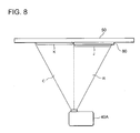
- FIG. 8 is a schematic view showing a configuration of a second embodiment of the present invention.
- the same elements as those in FIG. 3, showing the first embodiment, are denoted by common reference numerals.
- the second embodiment includes a projector 40A, the screen 50, and a standard white plate 80.
- the projector 40A projects an image corresponding to a given video signal, on the screen 50 but also projects separate images on two vertical or horizontal areas in the display area of the screen 50.
- the standard image is displayed on the standard white plate 80 in the correct colors.
- the standard image contains all of, for example, white, red, green, blue, and a memory color (for example, flesh color, plant green, or sky blue) .
- the projector 40A projects a corrected image in the area K of the screen 50 through a corrected image projecting area C, the corrected image having the same pattern as that of the standard image projected on the standard white plate 80.
- the user compares the standard image on the area J with the corrected image on the area K of the screen 50. Then, the user operates the operating section 43 so that the corrected image has the same hues as those of the standard image.
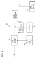
- FIG. 9 is a block diagram showing a configuration of the projector 40A.
- the projector 40A is provided with an internal image generating section 41A and a screen division processing section 45A having different configurations.
- the internal image generating section 41A holds, as internal images, a standard image to be projected on the standard white plate 80 as well as a corrected image to be projected on the area K of the screen 50.
- the image division processing section 45A adds correction data d to the image selected by the image switching section 42 to generate a color-adjusted corrected image and this video signal P.
- the video signal P is used to project the corrected image on the area K, while projecting the standard image on the area J.
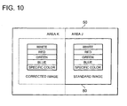
- FIG. 10 is a view showing an example of a standard image on the standard white plate 80 and a corrected image on the area K of the screen 50.
- FIG. 11 is a flow chart illustrating a color adjusting method used for the projector 40A. With reference to FIGS. 10 and 11, description will be given of the contents of processing executed in the color adjusting method used in the present embodiment.
- the image division processing section 45 divides the display area of the screen 50 into two horizontally arranged areas J and K (step B1, area dividing process) .
- the standard white plate 80 is installed on the area J of the screen 50.
- the video output section 70 projects a standard image on the standard white plate 80 (step B2, standard image projecting process). Further, the video output section 70 projects a corrected image on the area K of the screen 50, the corrected image having the same pattern as that of the standard image projected on the standard white plate 80 (step B3, corrected image projecting process).
- This corrected data creating process comprises at least one of a white adjusting process (step B4a), a color balance adjusting process (step B4b), and a specific color adjusting process (step B4c).
- the white adjusting process (step B4a) comprises paying attention to white parts of the corrected and standard images to make adjustment so that the luminance of the white part of the corrected image is closer to that of the standard image.
- the color balance adjusting process (step B4b) comprises pay attention to the color balance of the entire corrected and standard images to make adjustment so that the color balance of the corrected image is closer to that of the standard image. In this case, at least one of the luminance, hue, and saturation of red, green, and blue in the corrected image is adjusted.
- the specific color adjusting process comprises paying attention to a specific color (for example, a memory color such as flesh color or sky blue) part of each of the corrected and standard images to make adjustment so that the color of the specific color part of the corrected image is closer to that of the standard image.
- the color correction processing section 44 adds the correction data d to the video signal in to adjust the colors of the corrected image displayed on the screen 50 (step B5, color adjusting process).
- the screen division processing section 45A clears the division of the display area of the screen 50.
- the video output section 70 displays, on the screen 50, an image obtained by adjusting the color of the video signal in.
- the standard white plate 80 is installed in the area J of the screen 50. Then, the standard image on the standard white plate 80 is used as a reference to adjust the color of the corrected image on the area K of the screen 50. Consequently, even if the color of the screen 50 is different from white, the user can adjust the colors of the video signal in by operating the operating section 43 and executing a simple process.
- FIGS. 12 to 17 are views illustrating a third embodiment of the present invention.
- the third embodiment will be described with reference to FIGS. 12 to 17 and FIGS. 9 and 11, described in the second embodiment.
- the image division processing section 45 divides a display area on a wall 90 into two horizontally arranged areas J and K (step B1, area dividing process).
- a standard white screen 50A is installed on the area J of the wall 90.
- the video output section 70 projects a standard image on the screen 50A (step B2, standard image projecting process). Further, the video output section 70 projects a corrected image on the area K of the wall 90, the corrected image having the same pattern as that of the standard image projected on the screen 50A (step B3, corrected image projecting process).
- the user compares the two images and operates the operating section 43 so that the corrected image on the area K is closer to the standard image on the screen 50A.
- the color correction processing section 44 creates correction data d to correct the video signal in (step B4, corrected data creating process).
- This corrected data creating process comprises at least one of the white adjusting process (step B4a), the color balance adjusting process (step B4b), and the specific color adjusting process (step B4c).
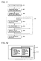
- the white adjusting process (step B4a) comprises paying attention to white parts of the corrected and standard images to make adjustment so that the luminance of the white part of the corrected image is closer to that of the standard image as shown in Fig. 12.
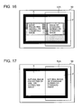
- the color balance adjusting process (step B4b) comprises pay attention to the color balance of the entire corrected and standard images to make adjustment so that the color balance of the corrected image is closer to that of the standard image as shown in FIGS. 13 to 16. In this case, at least one of the luminance, hue, and saturation of red, green, and blue in the corrected image is adjusted.
- the specific color adjusting process comprises paying attention to a specific color (for example, a memory color such as flesh color or sky blue) part of each of the corrected and standard images to make adjustment so that the color of the specific color part of the corrected image is closer to that of the standard image as shown in FIG. 17.
- the color correction processing section 44 adds the correction data d to the video signal in to adjust the colors of the corrected image displayed on the wall 90 (step B5, color adjusting process).
- the screen division processing section 45 clears the division of the display area of the wall 90.
- the video output section 70 displays, on the wall 90, an image obtained by adjusting the color of the video signal in.
- the third embodiment gives advantages similar to those of the second embodiment.
- the display area of the screen 50 is divided into the two horizontally arranged areas.
- the display area may be divided into two vertically arranged areas.
- the positions of the standard and the corrected images may be reversed. The positions and sizes of these two areas are arbitrary provided that the corrected image can be compared with the standard image.
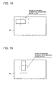
- only part of the display area may be used as shown in FIGS. 18 and 19.
- the white adjusting process (step A4a), color balance adjusting process (step A4b), and specific color adjusting process (step A4c) in FIG. 7 may be executed in an arbitrary order. Alternatively, only arbitrary one or two of these processes may be executed.
- the video output section 70 in FIG. 4 may be, for example, a single-plate type projector unit or a DLP (Digital Light Processing) projector.
- the DLP is a projection type video display method developed by Texas Instruments Incorporated, U.S. With the DLP, by controlling the directions of several million mirrors constituting an element and each having a size of 13 ⁇ 13 ⁇ m, light from a light source is reflected to project a video on the screen.
- the correction data d is such that the corrected image is closer to the standard image.
- the correction data d may be such that the standard image is closer to the corrected image.
- the color of the screen 50 can be determined.
- the corrected image is adjusted in accordance with the color of the screen 50.
- a plurality of images corrected using color correction parameters may be provided so that the colors of the right and left images can be matched with each other by selecting a proper image.
- the standard white screen 50A is installed on the area J of the wall 90.
- the standard image plate 60 in FIG. 3 may be installed, and a color adjusting method similar to that in the first embodiment may be carried out.
- color adjusting scroll bars corresponding to the respective colors may be displayed and used to adjust the luminance, hue, or saturation.
- color adjusting color palettes corresponding to the respective colors may be displayed so that a proper color can be selected from the color palette for color adjustment.
- a plurality of colors may be assumed for the screen 50, and a plurality of correction data may be created which correspond to the respective colors. Then, in the correction data creating process (steps A4 and B4) , a color closest to the current one of the screen 50 may be selected. Then, the correction data corresponding to the selected color may be used. The color may be selected by using a scroll bar displayed to select the luminance, hue, or saturation or displaying a color palette and selecting a proper color from this color palette.
Landscapes
- Engineering & Computer Science (AREA)
- Multimedia (AREA)
- Signal Processing (AREA)
- Projection Apparatus (AREA)
- Processing Of Color Television Signals (AREA)
- Video Image Reproduction Devices For Color Tv Systems (AREA)
Applications Claiming Priority (2)
| Application Number | Priority Date | Filing Date | Title |
|---|---|---|---|
| JP2002214597 | 2002-07-23 | ||
| JP2002214597 | 2002-07-23 |
Publications (2)
| Publication Number | Publication Date |
|---|---|
| EP1385340A2 true EP1385340A2 (fr) | 2004-01-28 |
| EP1385340A3 EP1385340A3 (fr) | 2005-08-10 |
Family
ID=29997235
Family Applications (1)
| Application Number | Title | Priority Date | Filing Date |
|---|---|---|---|
| EP03015500A Ceased EP1385340A3 (fr) | 2002-07-23 | 2003-07-09 | Méthode de traitement d'image pour un projecteur |
Country Status (3)
| Country | Link |
|---|---|
| US (1) | US6953250B2 (fr) |
| EP (1) | EP1385340A3 (fr) |
| CN (1) | CN100433817C (fr) |
Cited By (2)
| Publication number | Priority date | Publication date | Assignee | Title |
|---|---|---|---|---|
| CN100358350C (zh) * | 2004-03-24 | 2007-12-26 | 精工爱普生株式会社 | 投影机的控制 |
| EP2001245A2 (fr) | 2007-06-04 | 2008-12-10 | Sony Corporation | Générateur de signal de mire de réglage et procédé de génération, système de mesure de couleur et dispositif |
Families Citing this family (22)
| Publication number | Priority date | Publication date | Assignee | Title |
|---|---|---|---|---|
| FR2837056B1 (fr) * | 2002-03-07 | 2004-09-17 | France Telecom | Procede et systeme d'uniformisation du rendu colorimetrique d'une juxtaposition de surfaces d'affichage |
| KR100484139B1 (ko) * | 2002-05-17 | 2005-04-18 | 삼성전자주식회사 | 컨버전스 조정 기능 검사 장치 및 검사 방법 |
| KR20050080393A (ko) * | 2004-02-09 | 2005-08-12 | 삼성전자주식회사 | 색 좌표를 이용한 영상 조정 장치 및 그 방법 |
| JP4217643B2 (ja) * | 2004-03-18 | 2009-02-04 | キヤノン株式会社 | 画像濃度補正方法及び画像濃度補正システム |
| US20060033737A1 (en) * | 2004-08-16 | 2006-02-16 | Old William M | Methods and system for visualizing data sets |
| JP2007081685A (ja) * | 2005-09-13 | 2007-03-29 | Sony Corp | 画像信号処理装置、画像信号処理方法及び画像信号処理システム |
| US7905606B2 (en) * | 2006-07-11 | 2011-03-15 | Xerox Corporation | System and method for automatically modifying an image prior to projection |
| KR100834764B1 (ko) * | 2006-12-11 | 2008-06-05 | 삼성전자주식회사 | 투사면 조건을 고려하는 영상 투사 장치 및 방법 |
| US8428351B2 (en) | 2008-12-24 | 2013-04-23 | Brother Kogyo Kabushiki Kaisha | Image processing device |
| JP2010154009A (ja) * | 2008-12-24 | 2010-07-08 | Brother Ind Ltd | 画像処理装置と画像処理プログラム |
| JP4930503B2 (ja) * | 2008-12-25 | 2012-05-16 | ブラザー工業株式会社 | 画像処理装置と画像処理プログラム |
| CN102572456B (zh) * | 2010-12-22 | 2014-11-26 | 深圳Tcl新技术有限公司 | 一种眼镜式立体显示装置的色彩修正方法 |
| US9064312B2 (en) | 2011-09-23 | 2015-06-23 | The Regents Of The University Of California | Augmented reality using projector-camera enabled devices |
| CN103209311A (zh) * | 2012-01-14 | 2013-07-17 | 复旦大学 | 基于相机的多投影自动校正显示系统 |
| CN103974045B (zh) * | 2013-01-28 | 2016-07-06 | 联想(北京)有限公司 | 一种信息处理方法及电子设备 |
| DE102013206832A1 (de) * | 2013-04-16 | 2014-10-16 | Robert Bosch Gmbh | Bilddarstellungsvorrichtung, mobiltelefon und verfahren |
| CN103577185A (zh) * | 2013-09-16 | 2014-02-12 | 牛喆 | 还原网络购物颜色的一种方法 |
| JP2015206950A (ja) * | 2014-04-22 | 2015-11-19 | ソニー株式会社 | 情報処理装置、情報処理方法、プログラム、調整装置、及び画像表示システム |
| KR20160078023A (ko) * | 2014-12-24 | 2016-07-04 | 삼성전자주식회사 | 디스플레이 제어 장치 및 디스플레이 제어 방법 |
| JP6554887B2 (ja) * | 2015-04-14 | 2019-08-07 | 富士ゼロックス株式会社 | 画像生成装置、評価システムおよびプログラム |
| US9609176B2 (en) * | 2015-08-27 | 2017-03-28 | Nokia Technologies Oy | Method and apparatus for modifying a multi-frame image based upon anchor frames |
| CN114363592A (zh) * | 2021-12-10 | 2022-04-15 | 河南中光学集团有限公司 | 一种降低不同投影仪画面色差的方法 |
Citations (2)
| Publication number | Priority date | Publication date | Assignee | Title |
|---|---|---|---|---|
| US5638117A (en) | 1994-11-14 | 1997-06-10 | Sonnetech, Ltd. | Interactive method and system for color characterization and calibration of display device |
| US6036317A (en) | 1997-12-15 | 2000-03-14 | Seegers; Bjoern | Method of spectral or colorimetric characterization of a self-illuminating imaging system |
Family Cites Families (7)
| Publication number | Priority date | Publication date | Assignee | Title |
|---|---|---|---|---|
| US4106846A (en) * | 1976-11-15 | 1978-08-15 | Russin Morton S | Television color bar matching device |
| US5670985A (en) * | 1994-05-09 | 1997-09-23 | Apple Computer, Inc. | System and method for adjusting the output of an output device to compensate for ambient illumination |
| US6439722B1 (en) * | 1998-12-01 | 2002-08-27 | Gretagmacbeth | System and method for synchronizing the appearance of color images |
| JP3652194B2 (ja) * | 1999-12-09 | 2005-05-25 | 三菱電機株式会社 | 画像表示装置 |
| CN1353548A (zh) * | 2000-11-13 | 2002-06-12 | 台达电子工业股份有限公司 | 智慧型自动亮度对比及颜色补正系统 |
| US7283181B2 (en) * | 2002-01-31 | 2007-10-16 | Hewlett-Packard Development Company, L.P. | Selectable color adjustment for image display |
| US7184054B2 (en) * | 2003-01-21 | 2007-02-27 | Hewlett-Packard Development Company, L.P. | Correction of a projected image based on a reflected image |
-
2003
- 2003-07-09 EP EP03015500A patent/EP1385340A3/fr not_active Ceased
- 2003-07-11 US US10/616,948 patent/US6953250B2/en not_active Expired - Fee Related
- 2003-07-23 CN CNB031330533A patent/CN100433817C/zh not_active Expired - Fee Related
Patent Citations (2)
| Publication number | Priority date | Publication date | Assignee | Title |
|---|---|---|---|---|
| US5638117A (en) | 1994-11-14 | 1997-06-10 | Sonnetech, Ltd. | Interactive method and system for color characterization and calibration of display device |
| US6036317A (en) | 1997-12-15 | 2000-03-14 | Seegers; Bjoern | Method of spectral or colorimetric characterization of a self-illuminating imaging system |
Cited By (4)
| Publication number | Priority date | Publication date | Assignee | Title |
|---|---|---|---|---|
| CN100358350C (zh) * | 2004-03-24 | 2007-12-26 | 精工爱普生株式会社 | 投影机的控制 |
| EP2001245A2 (fr) | 2007-06-04 | 2008-12-10 | Sony Corporation | Générateur de signal de mire de réglage et procédé de génération, système de mesure de couleur et dispositif |
| EP2001245A3 (fr) * | 2007-06-04 | 2011-02-09 | Sony Corporation | Générateur de signal de mire de réglage et procédé de génération, système de mesure de couleur et dispositif |
| US8325238B2 (en) | 2007-06-04 | 2012-12-04 | Sony Corporation | Test pattern signal generator and generation method, color measurement system and display device |
Also Published As
| Publication number | Publication date |
|---|---|
| CN1477865A (zh) | 2004-02-25 |
| CN100433817C (zh) | 2008-11-12 |
| US6953250B2 (en) | 2005-10-11 |
| US20040017550A1 (en) | 2004-01-29 |
| EP1385340A3 (fr) | 2005-08-10 |
Similar Documents
| Publication | Publication Date | Title |
|---|---|---|
| US6953250B2 (en) | Color adjusting method for projector | |
| JP5971973B2 (ja) | 投影装置 | |
| US20190268579A1 (en) | Image projection system, projector, and control method for image projection system | |
| US8593482B2 (en) | Projector and method that performs a brightness adjustment and a color adjustment | |
| US12231825B1 (en) | Operating method for multi-screen projection system | |
| JP6019859B2 (ja) | プロジェクター、及び、プロジェクターにおける発光制御方法 | |
| JP2009200613A (ja) | プロジェクタおよびプロジェクタの表示調整方法 | |
| US8294834B2 (en) | Projection display apparatus for facilitating registration adjustment of colors of a display image | |
| US11604402B2 (en) | Projection system and projection method | |
| JP2019023711A (ja) | マルチプロジェクションシステム、プロジェクターおよびプロジェクターの制御方法 | |
| US20240146884A1 (en) | Display method, projector, and non-transitory computer-readable storage medium storing program | |
| JP4089483B2 (ja) | 異なった特徴の画像が混在する画像を表す画像信号の階調特性制御 | |
| US7002606B2 (en) | Image signal processing apparatus, image display apparatus, multidisplay apparatus, and chromaticity adjustment method for use in the multidisplay apparatus | |
| US7370980B2 (en) | Projection type video display | |
| JP2019024180A (ja) | プロジェクター、マルチプロジェクションシステムおよびプロジェクターの制御方法 | |
| US8167439B2 (en) | Image forming device | |
| JP2001016602A (ja) | 投写型液晶表示装置及び自動色相調整システム | |
| JP3776899B2 (ja) | プロジェクタ及びその色調整方法 | |
| Chen et al. | Fundamentals of scalable high-resolution seamlessly tiled projection system | |
| JP2004072760A5 (fr) | ||
| US10818271B2 (en) | Projecting apparatus and projecting method | |
| US10681315B2 (en) | Image display apparatus, image display system, and method for controlling image display apparatus | |
| JP2017010057A (ja) | プロジェクター、及び、プロジェクターにおける発光制御方法 | |
| JP2004015522A (ja) | 映像投射装置における色調整方法、及び該方法に用いられる色調整プログラム | |
| JP7327958B2 (ja) | 表示装置 |
Legal Events
| Date | Code | Title | Description |
|---|---|---|---|
| PUAI | Public reference made under article 153(3) epc to a published international application that has entered the european phase |
Free format text: ORIGINAL CODE: 0009012 |
|
| AK | Designated contracting states |
Kind code of ref document: A2 Designated state(s): AT BE BG CH CY CZ DE DK EE ES FI FR GB GR HU IE IT LI LU MC NL PT RO SE SI SK TR |
|
| AX | Request for extension of the european patent |
Extension state: AL LT LV MK |
|
| PUAL | Search report despatched |
Free format text: ORIGINAL CODE: 0009013 |
|
| AK | Designated contracting states |
Kind code of ref document: A3 Designated state(s): AT BE BG CH CY CZ DE DK EE ES FI FR GB GR HU IE IT LI LU MC NL PT RO SE SI SK TR |
|
| AX | Request for extension of the european patent |
Extension state: AL LT LV MK |
|
| 17P | Request for examination filed |
Effective date: 20050722 |
|
| AKX | Designation fees paid |
Designated state(s): DE GB |
|
| 17Q | First examination report despatched |
Effective date: 20060310 |
|
| RAP1 | Party data changed (applicant data changed or rights of an application transferred) |
Owner name: NEC DISPLAY SOLUTIONS, LTD. |
|
| RIC1 | Information provided on ipc code assigned before grant |
Ipc: H04N 9/73 20060101ALN20090218BHEP Ipc: H04N 9/31 20060101AFI20090218BHEP |
|
| STAA | Information on the status of an ep patent application or granted ep patent |
Free format text: STATUS: THE APPLICATION HAS BEEN REFUSED |
|
| 18R | Application refused |
Effective date: 20120212 |