EP1386028B1 - Verfahren und vorrichtung zum räumlichen schnellweben - Google Patents
Verfahren und vorrichtung zum räumlichen schnellweben Download PDFInfo
- Publication number
- EP1386028B1 EP1386028B1 EP02715284A EP02715284A EP1386028B1 EP 1386028 B1 EP1386028 B1 EP 1386028B1 EP 02715284 A EP02715284 A EP 02715284A EP 02715284 A EP02715284 A EP 02715284A EP 1386028 B1 EP1386028 B1 EP 1386028B1
- Authority
- EP
- European Patent Office
- Prior art keywords
- filling
- yarns
- yarn
- fabric
- warp
- Prior art date
- Legal status (The legal status is an assumption and is not a legal conclusion. Google has not performed a legal analysis and makes no representation as to the accuracy of the status listed.)
- Expired - Lifetime
Links
Images


Classifications
-
- D—TEXTILES; PAPER
- D03—WEAVING
- D03D—WOVEN FABRICS; METHODS OF WEAVING; LOOMS
- D03D41/00—Looms not otherwise provided for, e.g. for weaving chenille yarn; Details peculiar to these looms
- D03D41/004—Looms for three-dimensional fabrics
-
- D—TEXTILES; PAPER
- D03—WEAVING
- D03D—WOVEN FABRICS; METHODS OF WEAVING; LOOMS
- D03D25/00—Woven fabrics not otherwise provided for
- D03D25/005—Three-dimensional woven fabrics
-
- Y—GENERAL TAGGING OF NEW TECHNOLOGICAL DEVELOPMENTS; GENERAL TAGGING OF CROSS-SECTIONAL TECHNOLOGIES SPANNING OVER SEVERAL SECTIONS OF THE IPC; TECHNICAL SUBJECTS COVERED BY FORMER USPC CROSS-REFERENCE ART COLLECTIONS [XRACs] AND DIGESTS
- Y10—TECHNICAL SUBJECTS COVERED BY FORMER USPC
- Y10S—TECHNICAL SUBJECTS COVERED BY FORMER USPC CROSS-REFERENCE ART COLLECTIONS [XRACs] AND DIGESTS
- Y10S139/00—Textiles: weaving
- Y10S139/01—Bias fabric digest
Definitions
- the present invention relates generally to fabric formation and, more particularly, to a method for high speed three-dimensional woven fabric formation of structures including three substantially orthogonal yarn systems and a machine that incorporates this method.
- multi-layer fabrics including three-dimensional woven fabrics, particularly for use in aerospace and industrial applications and for use in resin-infused composite structures incorporating the same.
- specialized machines for making three-dimensional woven fabrics, particularly incorporating high performance fibers to improve the characteristics of the overall woven structure.
- "cramming" fabric is not used for large fabric dimensions; rather, it is used primarily as a border for towels and handkerchiefs.
- One significant problem with “crammed” fabric is a substantial lack of stability and control within the fabric due to the addition of picks without providing a warp or other angular interlocking of the picks. Uncontrolled shrinkage and wrinkling are prevalent in areas where "crammed” fabric is used.
- neither the two-dimensional fabrics nor the "crammed” fabrics that can be produced from a traditional two dimensional weaving machine at high speeds can provide adequate fabric characteristics to match those of true three-dimensional fabric structures.
- prior art three-dimensional weaving machines are capable of providing true three-dimensional fabric structures, including complex-shaped structures, the machine speeds are very slow. Typical speeds for specialized three-dimensional weaving machines are about 30 insertions per minute. Also, prior art 3-dimensional weaving machines require simultaneous stack filling insertion and continuously filing yarns. Therefore, no prior art has been capable of providing a high speed means for manufacturing true three-dimensional woven fabrics having three substantially orthogonal yarn systems. Thus, there remains a need for a method and machine for producing three-dimensional woven fabrics at reasonably high speeds. Furthermore, no prior art provides a high speed method or machine for forming three-dimensional fabric structures having a range of dimensions. Thus, there remains a need for a high speed method and machine for making three-dimensional woven fabric in a range of dimensions.
- the present invention is directed to a method for high speed formation of three-dimensional woven fabrics. Additionally, the invention is directed to a machine for making the same. The invention is applicable to the products made from the method and machine described, as no other machine is capable of making these products at high speeds.
- the invention includes a method for providing at least two warp yarn systems having approximately zero crimp and at least three filling insertions having approximately zero crimp, wherein the warp and filling yarns are non-interlacing with each other, and are secured as an integral fabric via at least one vertical or Z yarn system provided via two harness frames.
- the present invention provides a method and machine for high speed formation of true three-dimensional woven fabric with substantially orthogonal yarn systems having superior structural uniformity and/or continuity and performance characteristics than any prior art structure or substitute.
- the present invention provides a method of manufacturing three-dimensional fabrics in a. limited range of dimensions and densities using a single fabric-forming machine with no additional equipment or separate processes required, these dimensions are limited to the rapier machine width and to fabrics having only two or three warp yarn layers.
- the three-dimensional woven fabrics produced by the method and machine according to the present invention are suitable for forming rigid composite structures that do not require joining, splicing, or otherwise connecting, patterning, creating cut-out regions or overlapping material to form the final structure, shape or dimensions in order to conform to a predetermined shaped structure or component.
- the shaped three-dimensional fabric structure may be formed into a rigid composite structure via the addition of a resin or similar hardening material.
- one aspect of the present invention is to provide a method for high speed formation of three-dimensional woven fabric structures by providing at least two warp yarn systems having approximately zero crimp and at least three filling insertions having approximately zero crimp, wherein the warp and filling yarns are non-interlacing with each other, and are secured as an integral fabric via at least one vertical or Z yarn system provided via two harness frames.
- Another aspect of the present invention is to provide a high speed machine for forming three-dimensional woven fabric structures by providing a rapier machine that is modified to include at least two distinct warp yarn systems having approximately zero crimp and at least three filling insertions having approximately zero crimp per insertion cycle or series, wherein the warp and filling insertions are non-interlacing with each other, and are secured as an integral fabric via at least one vertical or Z yarn system provided via two harness frames. Additionally, it is an aspect of the present invention to provide a three-dimensional woven fabric structure formed via the high speed method and machine according to the present invention.
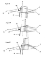
- FIG. 2A-2F a process schematic diagram of a three-dimensional (3-D) weaving arrangement having at least two warp or X-direction yarn systems, at least three filling insertions, each having a Y-direction yarn pairing, per insertion cycle or series, and at least one vertical or Z-direction yarn system using at least two harness frames is shown according to the present invention.
- the process includes providing at least two X-direction warp yarn systems drawn through at least 2 harnesses having approximately zero crimp and at least three Y-direction filling insertions including a pair of filling yarns in each insertion having approximately zero crimp, wherein the warp and filling yarns are non-interlacing with each other.
- Figure 1 is a perspective view of a fabric produced according to the method of the preferred embodiment produced according to the present invention, namely a 3-D orthogonal woven structure, generally referenced 10, wherein the arrangement shows two warp layers forming the X-direction yarn system 12, six harnesses 20 (shown in Figure 2) four for controlling and guiding X-direction yarns 12 and two for controlling and guiding Z-direction yarn systems 14, more specifically, four harness sets for the X-direction yarns (W1, W2), two harness sets for the Z-direction yarn systems (Z1, Z2), and three filling insertion layers 16 forming the Y-direction yarn system.
- the X-direction and Y-direction yarns are non-interlacing and are layered vertically at substantially right angles to each other.
- the modified weaving machine and method according to the present invention require not more than three warp layers and four filling insertion layers; preferably, the best embodiment for the modified weaving machine and method according to the present invention require two warp layers and three filling layers. Increasing the number of layers of warp (X-direction) and filling insertion (Y-direction) layers slows the process substantially such that the modified machine and method do not produce at substantially high speeds.
- the X-direction yarn system and Y-direction yarn systems are non-interlacing, that is, no interlacing cross-over points occur when the two systems are introduced to form two of the three substantially orthogonal yarn systems in the fabric body.
- the Y-direction yarn system and the Z-direction yarn system can be balanced or non-balanced.
- the Z-direction yarn system provides the structural separation and control of position between the X- and Y-direction yarn systems during weaving and in the finished woven structure.
- the process by which the three-dimensional woven fabric is formed at high speed according to the present invention will now be generally described with reference to the schematic shown in Figures 2A-2F.
- the warp yarns 12 are drawn in under tension from a warp and tension system (not shown) between the heddles of harnesses W1 to W2, and through a beat up reed 18 and to the fabric formation zone 22.
- the filling insertion 16 or sets of filling yarns F1, F2, F3, F4, F5, F6 are inserted between the warp layers using fill insertion means, preferably a rapier system of a modified rapier machine (not shown) using fill insertion rapiers modified to carry paired filling yarns simultaneously in one pick.
- fill insertion means preferably a rapier system of a modified rapier machine (not shown) using fill insertion rapiers modified to carry paired filling yarns simultaneously in one pick.
- neither the X-direction nor the Z-direction harnesses cross for every filling insertion, rather the Z-direction yarns cross for every completed filling insertion cycle comprising three filling insertions F1, F2, F3 and/or F4, F5, F6 in the sections of the fabric to form the main body of the fabric 32.
- a completed filling insertion cycle includes two warp or X-direction yarn layers that run parallel to each other in spaced apart configuration as shown in Figs. 2A-2F and three filling insertion or Y-direction layers having two yarns per filling insertion or pick, wherein the three filling insertions are inserted in a vertically parallel, spaced apart configuration shown in Figs. 2A-2F within a unique shed for each pick F1, F2, F3, F4, F5, F6, as shown, and a single motion cycle of the Z-direction yarn harnesses for each cycle F1, F2, F3 and/or F4, F5, F6.
- the warp advance and fabric take-up are coordinated to activate only after a filling insertion cycle is completed; a filling insertion cycle, including three filling insertions F1, F2, F3 and/or F4, F5, F6 provides a half fabric repeat cycle or one weaving cycle.
- harnesses Z1, Z2 which are carrying Z-direction yarns, cross for every fill insertion cycle to the bottom and top parts, respectively.
- This method provides a traditional 3-D weaving pattern, wherein there is not separation between top and bottom parts, i.e., the entire fabric has an integral, unitary woven construction, as shown in Fig. 1.
- Figs. 2A-2F when the Z-direction yarn system components are in an "open" position wherein select, predetermined harnesses Z1, Z2 and W1, W2 are raised or lowered in pairs respectively to form an angular opening or shed opening between the X-direction yarn systems and the Z-direction yarns, thereby forming a unique shed opening for each filling insertion, then a filling insertion or filling yarn pair is inserted therebetween.
- one filling insertion having two filling yarns is inserted between each layer of X-direction or warp yarns to provide at least three filling yarns in a substantially vertical, stacked and spaced-apart arrangement wherein each filling yarn is separated from another by a layer of X-direction or warp yarns.
- FIG. 2A-2F illustrates an 3-D weaving process schematic according to the present invention
- Figs. 2A-2F two Z-direction yarn harnesses are used in the configuration according to the present invention.
- a complete fill insertion cycle consists of three steps and is described as follows: for pick #1, as shown in Fig. 2A, the Z-direction yarn in harness Z1 and the X-direction yarns in harnesses W1 and W2 are positioned up and the Z-direction yarn in harness Z2 is positioned down to form an open shed for the introduction or insertion of the first Y-direction filling insertion yarns F1.
- the Y-direction filling insertion yarns F1 are inserted across the width of the machine by a rapier and each end of the Y-direction yarns is cut to form a finite component.
- Beat-up by the reed 18 then occurs.
- the Z-direction yarn in harness Z1 and the X-direction yarns in harnesses W2 are positioned up, the Z-direction yarn in harness Z2 and the X-direction yarns in harnesses W1 are positioned down to form an open shed for the introduction or insertion of the second Y-direction filling insertion yarns F2.
- the Y-direction filling insertion yarns F2 are inserted across the width of the machine by a rapier and each end of the Y-direction yarns is cut to form a finite component. Beat-up by the reed 18 then occurs.
- the Z-direction yarn in harness Z1 is positioned up and the Z-direction yarn in harness Z2, the X-direction yarns in harnesses W1 and W2 are positioned down to form an open shed for the introduction or insertion of the third Y-direction filling insertion yarns F3.
- the Y-direction filling insertion yarns F3 are inserted across the width of the machine by a rapier and each end of the Y-direction yarns is cut to form a finite component. Beat-up by the reed 18 then occurs.
- take-up then occurs, wherein take-up consists of advancing the X-direction warp yarns by adjusting the warp yarn system drums and a take-up roll in coordinated rotational movement until a filling insertion cycle is completed.
- the positions of the Z-direction harnesses Z1 and Z2 are reversed, and the cycle occurs as follows: for pick #4, as shown in Fig. 2D, the Z-direction yarn in harness Z2 is positioned up and the Z-direction yarn in harness Z1, the X-direction yarns in harnesses W1 and W2 are positioned down to form an open shed for the introduction or insertion of the fourth Y-direction filling insertion yarns F4.
- the Y-direction filling insertion yarns F4 are inserted across the width of the machine by a rapier and each end of the Y-direction yarns is cut to form a finite component. Beat-up by the reed 18 then occurs. Subsequently for pick #5, as shown in Fig. 2E, the Z-direction yarn in harness Z2 and the X-direction yarns in harnesses W1 are positioned up and the Z-direction yarn in harness Z1 and the X-direction yarns in harnesses W2 are positioned down to form an open shed for the introduction or insertion of the fifth Y-direction filling insertion yarns F5.
- the Y-direction filling insertion yarns F5 are inserted across the width of the machine by a rapier and each end of the Y-direction yarns is cut to form a finite component. Beat-up by the reed 18 then occurs. Subsequently for pick #6, as shown in Fig. 2F, the Z-direction yarn in harness Z2 and the X-direction yarns in harnesses W1 and W2 are positioned up and the Z-direction yarn in harness Z1 is positioned down to form an open shed for the introduction or insertion of the sixth Y-direction filling insertion yarns F6.
- the Y-direction filling insertion yarns F6 are inserted across the width of the machine by a rapier and each end of the Y-direction yarns is cut to form a finite component. Beat-up by the reed 18 then occurs. Take-up then occurs.
- the rapier system of the machine required modification to reasonably handle each filling insertion having two filling yarns, particularly since the yarns were high performance fibers selected from the group consisting of Kevlar, fiberglass, and carbon. This provides for high speed production of an orthogonal 3D woven structure according to the present invention.
- a tension compensation system for X-, Y-, and Z-direction yarns is constructed and arranged to maintain tension levels during weaving process.
- the Y-direction yarn is maintained under at least a minimum tension supplied between the yarn supply packages and the rapier.
- the X-direction yarn systems are maintained under a tension system incorporating the warp beam(s) and take-up roll. The X-direction or warp yarns are advanced only after a complete Y-direction yarn insertion cycle is completed.
- Each Y-direction yarn insertion cycle includes at least three Y-direction yarn insertions aligned in a substantially vertical, spaced apart columnar arrangement separated by X-direction or warp yarn layers. Additionally, as the Z-direction yarns move and are subject to the tension compensation system, the length of the Z-direction yarns also changes, thus making the tension control necessary. Typically, tension ranges for the tension compensation system are between about 20 gram to 400 gram, depending upon the type and tow size of Z-direction yarns used in the structure, fabric thickness, the number of warp layers, and other process parameters.
- the present invention provides uniform and controlled distribution and arrangement of each of the yarns in each yarn system throughout the woven fabric body.
- each of the filling insertions 16 is inserted simultaneously in a continuous looped configuration; whereas the method according to the present invention provides a staggered, separate and serial introduction of each Y-direction yarn pair in each filling insertion cycle, thereby providing for rapid introduction of filling and high speed three-dimensional weaving.
- the three-dimensional woven fabrics have two or three X-direction yarn warp layers.
- the warp ends are between 1.5 to 12 ends per cm per layer.
- the fill insertion per unit length is between 1.5 to 12 insertions per cm.
- the three-dimensional woven fabrics have three or four Y-direction yarn filling layers, respectively to the number of X-direction warp layers, separated by the warp layers.
- the combination of three layers of Y-direction yarn filling layers separated by two X-direction yarn warp layers creates a fabric referred to as "2.5" as calculated from the average of the X- and Y-direction yarn layers.
- the combination of four layers of Y-direction yarn filling layers separated by three X-direction yarn warp layers creates a fabric referred to as "3.5" as calculated from the average of the X- and Y-direction yarn layers.
- the three-dimensional (3-D) fabric according to the present invention is formed of at least one high-performance fiber array within a three-dimensional weave construction, which has at least two warp layers but not more than three warp layers.
- the 3-D fabric is engineered and constructed to form a predetermined structure, namely either a 2.5 or 3.5 rectangular cross-sectional 3-D woven fabric.
- the dimensions of the overall structure and of the cross-section can be varied, based upon the desired size of the fabric and the dimensions of the rapier weaving machine on which the fabric is being manufactured.
- Speeds possible with the method and machine according to the present invention are between about 150 to about 350 individual Y-direction yarn insertions per minute, preferably between about 250 to about 300 individual Y-direction yarn insertions per minute.
- the weaving speed would be between about 50 to about 117 insertion cycles per minute, preferably between about 80 to about 100 insertion cycles per minute.
- the weaving speed would be between about 30 to about 70 insertion cycles per minute, preferably between about 50 to about 60 insertion cycles per minute.
- the method and machine according to the present invention is capable of producing a limited range of rectangular cross-sectioned 3-D woven fabrics, as illustrated in Fig. 1, generally referenced 10, which shows three substantially perpendicular yarn systems, respectively positioned in an X direction, a Y direction, and a Z direction, as shown.
- the 3-D woven fabric includes at least one high performance fiber array in one of the X, Y, or Z directions.
- the warp direction, or X direction comprises high performance fibers selected from the group consisting of carbon, Kevlar, and fiberglass.
- the Y and Z directions also include similar high performance fibers for increased impact resistance, strength, shear strength, compression characteristics, enhanced resistance to delamination, and overall uniformity and structural integrity.
- the fabric is formed of high-performance fiber selected from the group consisting of Kevlar, fiberglass, carbon, and the like.
- high-performance fibers having a tensile strength of greater than about 5 grams per denier may be used; preferably, the high performance fibers have a tensile strength of greater than 7 grams per denier.
- Fabric dimensions according to the present invention may vary, preferably the width of the finished fabric is between about 20 to about 70 inches wide, more preferably about 50 to about 64 inches wide in the Y-direction.
- width of the finished fabric is between about 20 to about 70 inches wide, more preferably about 50 to about 64 inches wide in the Y-direction.
- traditional true 3-D woven fabrics could only be produced in dimensions of up to 20 inches wide, due to machine and method restrictions for the configuration wherein all filling insertions of Y-direction yarns are made simultaneously for a given cycle.
- the present invention advantageously permits higher speed filling insertions and greater fabric widths by adopting individual filling yarn insertions that in series produce a single filling insertion cycle.
- the present invention is directed to a method for high speed formation of a 3-dimensional woven fabric, specifically in a preferred embodiment a two layer X-direction and three layer Y-direction configuration, for aerospace and industrial applications of the finished fabrics and composites made therefrom, including the steps set forth in the foregoing of providing at least two warp yarn systems having approximately zero crimp and at least three filling yarns having approximately zero crimp, wherein the warp and filling yarns are non-interlacing with each other, and are secured as an integral fabric via at least one vertical or Z yarn system provided via two harness frames; introducing each of the at least three filling yarns to form a complete filling insertion cycle without advancing the X-direction warp yarns; changing the position of the Z-direction yarns by moving the harnesses to cross each other from top to bottom and vice versa; advancing the warp yarn systems at a predetermined rate; and repeating the previous steps, thereby forming a 3-dimensional woven fabric at high speed and large dimensions.
Landscapes
- Engineering & Computer Science (AREA)
- Textile Engineering (AREA)
- Looms (AREA)
- Woven Fabrics (AREA)
- Yarns And Mechanical Finishing Of Yarns Or Ropes (AREA)
- Braiding, Manufacturing Of Bobbin-Net Or Lace, And Manufacturing Of Nets By Knotting (AREA)
Claims (13)
- Verfahren zum Bilden einer dreidimensionalen Webfaserstruktur (10), wobei das Verfahren die folgenden Schritte umfasst:Bereitstellen wenigstens zweier X-Richtungs-Kettgarnsysteme (12), die durch wenigstens 2 Harnische (W1, W2) gezogen werden, mit angenähert null Kräuselung und wenigstens dreier Y-Richtungs-Schusseinfügungen (F1, F2, F3), die in jeder Einfügung ein Paar Schussgarne (16) mit angenähert null Kräuselung enthalten, wobei die Kett- und die Schussgarne nicht miteinander verschlungen werden;Bereitstellen wenigstens eines vertikalen oder Z-Garnsystems (14), das über wenigstens zwei Harnischrahmen (Z1, Z2) bereitgestellt wird, die so bewegt werden, dass sie die Kett- und Schussgarne befestigen, um einen einteiligen Stoff zu bilden;Einführen jeder der wenigstens drei Schusseinfügungen (F1, F2, F3) der Reihe nach, wobei jede in eine einzige Fachöffnung (22) eingeführt und durch eine Ebene von X-Richtungs-Kettgarnen getrennt wird, wobei die Einfügungen eine im Wesentlichen vertikale Ausrichtung aufeinander bilden;Fertigstellen eines Schusseinfügungszyklus, ohne die X-Richtungs-Kettgarne vorzuschieben;Vorschieben eines Riets (18) in einer Ladenanschlagbewegung zu einem Stoff (32), der durch die Garne gebildet wird, wobei auf jede Schusseinfügung der Rietladenanschlag folgt, und Ändern der Stellung der X-Richtungs-Harnische, die die X-Richtungs-Kettgarne steuern, um eine neue Fachöffnung zu bilden;Ändern der Stellung der Z-Richtungs-Garne (14), indem die Z-Richtungs-Harnische (Z1, Z2) von oben nach unten und umgekehrt bewegt werden, so dass sie sich kreuzen;Vorschieben der Kettgarnsysteme (12) mit einer vorgegebenen Rate, die mit einer Stoffaufwickelrate abgestimmt ist;Befestigen der X-Richtungs-Kettgarne und der Y-Richtungs-Schusseinfügungen aneinander zu einem einteiligen Stoff über wenigstens ein vertikales oder Z-Garnsystem (14), das über zwei Harnischrahmen (Z1, Z2) vorgesehen ist; undWiederholen der vorherigen Schritte und dadurch Bilden eines 3-dimensionalen orthogonalen Webstoffs.
- Verfahren nach Anspruch 1, bei dem die Struktur wenigstens drei Garnsysteme, jeweils eines in einer X-, in einer Y- und in einer Z-Richtung, umfasst, wodurch eine im Wesentlichen orthogonale 3D-Webstruktur gebildet wird.
- Verfahren nach Anspruch 1, bei dem die Struktur aus wenigstens einem Hochleistungs-Fasertyp gebildet wird.
- Verfahren nach Anspruch 1, bei dem die Struktur für jeden Schusseinfügungszyklus unter Verwendung wenigstens zweier Z-Richtungs-Harnische gebildet wird, um die Z-Richtungs-Garnstellungen so zu steuern, dass die einzige Fachöffnung gebildet wird.
- Verfahren nach Anspruch 1, bei dem die Struktur für jede Schusseinfügung unter Verwendung wenigstens zweier Z-Richtungs-Harnische gebildet wird, um die Z-Richtungs-Garnstellungen so zu steuern, dass die einzige Fachöffnung gebildet wird.
- Verfahren nach Anspruch 1, bei dem die dreidimensionalen Stoffdimensionen eine Y-Richtungs-Breite zwischen etwa 20 bis etwa 70 Zoll breit enthalten.
- Verfahren nach Anspruch 1, bei dem die dreidimensionalen Stoffdimensionen eine Y-Richtungs-Breite zwischen etwa 50 bis etwa 64 Zoll breit enthalten.
- Verfahren nach Anspruch 1, bei dem die Y-Richtungs-Schichten drei Schichten sind und bei dem die X-Richtungs-Schichten zwei Schichten sind.
- Verfahren nach Anspruch 1, bei dem die Y-Richtungs-Schichten vier Schichten sind und bei dem die X-Richtungs-Schichten drei Schichten sind.
- Verfahren nach Anspruch 1, bei dem die Y-Richtungs-Schusseinfügungen mit einer Geschwindigkeit zwischen etwa 150 bis etwa 350 Y-Richtungs-Einfügungen pro Minute gebildet werden.
- Verfahren nach Anspruch 1, bei dem die Y-Richtungs-Schusseinfügungen mit einer Geschwindigkeit zwischen etwa 250 bis etwa 300 Y-Richtungs-Einfügungen pro Minute gebildet werden.
- Verfahren nach Anspruch 1, das ferner die folgenden Schritte enthält:Bereitstellen der Z-Richtungs-Garne in zwei Harnischen Z1, Z2 und der X-Richtungs-Garne in Harnischen W1 und W2;Positionieren der Z-Richtungs-Garne im Harnisch Z1 und der X-Richtungs-Garne in den Harnischen W1 und W2 in einer AUF-Stellung und der Z-Richtungs-Garne im Harnisch Z2 in einer AB-Stellung und dadurch Bilden eines ersten offenen Fachs für die Einführung einer ersten Y-Richtungs-Schusseinfügung F1;Einfügen der Y-Richtungs-Schusseinfügungsgarne F1 über ein Greiferstabsystem quer über die Breite der Webmaschine und Abschneiden jedes Endes der Y-Richtungs-Schusseinfügung, um eine endliche Schusseinfügung F1 zu bilden;Aktivieren eines Rietladenanschlags gegen den Stoff, der durch die Garne gebildet wird;Positionieren des Z-Richtungs-Garns im Harnisch Z1 und der X-Richtungs-Garne in den Harnischen W2 in einer AUF-Stellung und Positionieren des Z-Richtungs-Garns im Harnisch Z2 und der X-Richtungs-Garne in den Harnischen W1 in einer AB-Stellung, um ein zweites offenen Fach für die Einführung einer zweiten Y-Richtungs-Schusseinfügung F2 zu bilden;Einfügen der zweiten Y-Richtungs-Schusseinfügung F2 über ein Greiferstabsystem quer über die Breite der Webmaschine und Abschneiden jedes Endes der Y-Richtungs-Schusseinfügung, um eine endliche Schusseinfügung F2 zu bilden;Aktivieren eines Rietladenanschlags gegen den Stoff, der durch die Garne gebildet wird;Positionieren des Z-Richtungs-Garns im Harnisch Z1 in einer AUF-Stellung und Positionieren des Z-Richtungs-Garns im Harnisch Z2 und der X-Richtungs-Garne in den Harnischen W1 und W2 in einer AB-Stellung, um ein offenen Fach für die Einführung oder Einfügung der dritten Y-Richtungs-Schusseinfügungsgarne F3 zu bilden;Einfügen einer dritten Y-Richtungs-Schusseinfügung F3 über ein Greiferstabsystem quer über die Breite der Webmaschine und Abschneiden jedes Endes der Y-Richtungs-Einfügungs-Schusseinfügung, um eine endliche Schusseinfügung F3 zu bilden;Aktivieren eines Rietladenanschlags gegen den Stoff, der durch die Garne gebildet wird;Aktivieren eines Kettvorschubs und abgestimmten Aufwickelns des Stoffs nach der Fertigstellung des Schusseinfügungszyklus, der die fertig gestellte Schusseinfügung der ersten, der zweiten und der dritten Schusseinfügung in einer voneinander beabstandeten vertikal ausgerichteten Stellung in dem Stoff enthält;Vertauschen der Stellungen der Z-Richtungs-Harnische Z1 und Z2;Positionieren des Z-Richtungs-Garns im Harnisch Z2 in der AUF-Stellung und Positionieren des Z-Richtungs-Garns im Harnisch Z1 und der X-Richtungs-Garne in den Harnischen W1 und W2 in der AB-Stellung, um ein offenes Fach für die Einführung der vierten Y-Richtungs-Schusseinfügung F4 zu bilden;Einfügen einer vierten Y-Richtungs-Schusseinfügung F4 über ein Greiferstabsystem quer über die Breite der Webmaschine und Abschneiden jedes Endes der Y-Richtungs-Schusseinfügung, um eine endliche Schusseinfügung F4 zu bilden;Aktivieren eines Rietladenanschlags gegen den Stoff, der durch die Garne gebildet wird;Positionieren des Z-Richtungs-Garns im Harnisch Z2 und der X-Richtungs-Garne in den Harnischen W1 in der AUF-Stellung und Positionieren des Z-Richtungs-Garns im Harnisch Z1 und der X-Richtungs-Garne in den Harnischen W2 in einer AB-Stellung, um ein offenes Fach für die Einführung fünfter Y-Richtungs-Schusseinfügungsgarne F5 zu bilden;Einfügen der fünften Y-Richtungs-Schusseinfügung F5 über ein Greiferstabsystem quer über die Breite der Webmaschine und Abschneiden jedes Endes der Y-Richtungs-Schusseinfügung, um eine endliche Schusseinfügung F5 zu bilden;Aktivieren eines Rietladenanschlags gegen den Stoff, der durch die Garne gebildet wird;Positionieren des Z-Richtungs-Garns im Harnisch Z2 und der X-Richtungs-Garne in den Harnischen W1 und W2 in der AUF-Stellung und des Z-Richtungs-Garns im Harnisch Z1 in einer AB-Stellung, um ein offenen Fach für die Einführung oder Einfügung der sechsten Y-Richtungs-Schusseinfügung F6 zu bilden;Einfügen der sechsten Y-Richtungs-Schusseinfügung F6 über ein Greiferstabsystem quer über die Breite der Webmaschine und Abschneiden jedes Endes der Y-Richtungs-Schusseinfügungen, um eine endliche Schusseinfügung F6 zu bilden;Aktivieren eines Rietladenanschlags gegen den Stoff, der durch die Garne gebildet wird;Aktivieren eines Kettvorschubs und abgestimmten Aufwickelns des Stoffs nach der Fertigstellung des Schusseinfügungszyklus, der die fertig gestellte Schusseinfügung der vierten, der fünften und der sechsten Schusseinfügung in einer voneinander beabstandeten vertikal ausgerichteten Stellung in dem Stoff enthält;Vertauschen der Stellungen der Z-Richtungs-Harnische Z1 und Z2;Wiederholen des Stoffwiederholungszyklus, der alle hier aufgeführten Schritte enthält.
- Maschine zum Herstellen einer dreidimensionalen Hochgeschwindigkeits-Webstoffstruktur (10), wobei die Maschine einen modifizierten Greiferstabwebstuhl umfasst, der so konfiguriert ist, dass er Folgendes bereitstellen kann:wenigstens zwei Kettgarnsysteme (12) mit angenähert null Kräuselung;wenigstens drei Schusseinfügungen (F1, F2, F3) pro Einfügungszyklus, wobei jede Schusseinfügung ein Schussgarnpaar (16) mit angenähert null Kräuselung enthält und wobei die Kett- und Schusseinfügungen in abwechselnden, orthogonalen Schichten positioniert sind und die Kett- und Schusseinfügungen nicht miteinander verschlungen sind;wenigstens ein vertikales oder Z-Garnsystem (14), das über wenigstens zwei Harnisch-Rahmen (Z1, Z2) vorgesehen ist, die so bewegt werden, dass sie die Kett- und Schussgarne so befestigen, dass ein einteiliger Stoff gebildet wird; wodurch jedes der wenigstens drei Schussgarnpaare in einer Schusseinfügung in eine einzige Fachöffnung (22) eingeführt werden kann, um einen vollständigen Schusseinfügungszyklus zu bilden, ohne die X-Richtungs-Kettgarne vorzuschieben, indem die Kettgarnsystemtrommeln und eine Aufwickelrolle in abgestimmter Drehbewegung eingestellt werden, bis ein Schusseinfügungszyklus abgeschlossen ist; undein Zugsystem zum Vorschieben der Kettgarnsysteme (12) mit einer vorgegebenen Rate, die mit einem Aufwickeln für den Stoff (32) abgestimmt ist, wobei das Aufwickeln und der Kettvorschub bei der Fertigstellung des Schusseinfügungszyklus, der die Hälfte eines Stoffmuster-Wiederholungszyklus ist, aktiviert werden können, wodurch eine Maschine für die schnelle Bildung eines 3-dimensionalen Webstoffs mit hoher Geschwindigkeit und großen Dimensionen bereitgestellt wird.
Applications Claiming Priority (3)
| Application Number | Priority Date | Filing Date | Title |
|---|---|---|---|
| US816835 | 1986-01-07 | ||
| US09/816,835 US6315007B1 (en) | 2001-03-23 | 2001-03-23 | High speed three-dimensional weaving method and machine |
| PCT/US2002/011305 WO2002077340A1 (en) | 2001-03-23 | 2002-03-22 | High speed three-dimensional weaving method & machine |
Publications (3)
| Publication Number | Publication Date |
|---|---|
| EP1386028A1 EP1386028A1 (de) | 2004-02-04 |
| EP1386028A4 EP1386028A4 (de) | 2004-04-14 |
| EP1386028B1 true EP1386028B1 (de) | 2006-10-04 |
Family
ID=25221735
Family Applications (1)
| Application Number | Title | Priority Date | Filing Date |
|---|---|---|---|
| EP02715284A Expired - Lifetime EP1386028B1 (de) | 2001-03-23 | 2002-03-22 | Verfahren und vorrichtung zum räumlichen schnellweben |
Country Status (6)
| Country | Link |
|---|---|
| US (1) | US6315007B1 (de) |
| EP (1) | EP1386028B1 (de) |
| AT (1) | ATE341653T1 (de) |
| CA (1) | CA2441418C (de) |
| DE (1) | DE60215146D1 (de) |
| WO (1) | WO2002077340A1 (de) |
Cited By (1)
| Publication number | Priority date | Publication date | Assignee | Title |
|---|---|---|---|---|
| FR2917099A1 (fr) | 2007-06-06 | 2008-12-12 | Ensait | Procede de fabricaiton d'un materiau composite, notamment pour la protection balistique, et materiau composite obtenu. |
Families Citing this family (29)
| Publication number | Priority date | Publication date | Assignee | Title |
|---|---|---|---|---|
| US20040243148A1 (en) * | 2003-04-08 | 2004-12-02 | Wasielewski Ray C. | Use of micro- and miniature position sensing devices for use in TKA and THA |
| US6971476B2 (en) * | 2003-09-05 | 2005-12-06 | D B Industries, Inc. | Safety harness |
| CN1317437C (zh) * | 2004-05-10 | 2007-05-23 | 中材科技股份有限公司 | 异形截面机织三维织物的织造工艺 |
| CA2598391C (en) | 2005-02-18 | 2012-05-22 | Ray C. Wasielewski | Smart joint implant sensors |
| US7655581B2 (en) * | 2005-11-17 | 2010-02-02 | Albany Engineered Composites, Inc. | Hybrid three-dimensional woven/laminated struts for composite structural applications |
| CN1888177B (zh) * | 2006-07-31 | 2010-06-02 | 赵祖良 | 用在多层织机上可实现经纬平交加z向纱织法的机构 |
| US9440055B2 (en) | 2006-10-12 | 2016-09-13 | C.R. Bard, Inc. | Inflatable structure with braided layer |
| FR2907803B1 (fr) * | 2006-10-27 | 2009-01-23 | Airbus France Sas | Systeme de tissage d'un angle continu |
| US7628179B2 (en) * | 2007-07-27 | 2009-12-08 | 3 TEX, Inc. | 3-D woven fabric and methods for thick preforms |
| US8440276B2 (en) * | 2008-02-11 | 2013-05-14 | Albany Engineered Composites, Inc. | Multidirectionally reinforced shape woven preforms for composite structures |
| US8029566B2 (en) * | 2008-06-02 | 2011-10-04 | Zimmer, Inc. | Implant sensors |
| US8959664B2 (en) * | 2009-02-09 | 2015-02-24 | D B Industries, Llc | Harness webbing protection system |
| US7968477B1 (en) | 2009-02-10 | 2011-06-28 | E. I. Du Pont De Nemours And Company | Fabric assembly suitable for resisting ballistic objects and method of manufacture |
| US7836917B1 (en) * | 2009-11-18 | 2010-11-23 | Paradox LLC | Weaving connectors for three dimensional textile products |
| US7841369B1 (en) * | 2009-11-18 | 2010-11-30 | vParadox LLC | Weaving process for production of a full fashioned woven stretch garment with load carriage capability |
| CN102660828B (zh) * | 2009-12-17 | 2015-02-04 | 财团法人纺织产业综合研究所 | 立体梭织织物 |
| US8446077B2 (en) | 2010-12-16 | 2013-05-21 | Honda Motor Co., Ltd. | 3-D woven active fiber composite |
| US20130065042A1 (en) | 2011-03-11 | 2013-03-14 | The Board Of Trustees Of The University Of Illinois | Micro-Vascular Materials And Composites For Forming The Materials |
| WO2012125164A1 (en) * | 2011-03-16 | 2012-09-20 | Stoneferry Technology, Inc | An integrated hollow fabric structure |
| EP2828427B1 (de) | 2012-03-23 | 2017-12-20 | Nandan Khokar | Ein 3d-textilstoff und eine verfahren und vorrichtung zur herstellung eines solchen 3d fabric |
| FR2991228B1 (fr) | 2012-05-29 | 2015-03-06 | Airbus Operations Sas | Procede et dispositif de realisation d'un panneau composite auto-raidi |
| WO2014145675A1 (en) | 2013-03-15 | 2014-09-18 | Hollander Jonathan Marc | Methods for three-dimensional weaving of composite preforms and products with varying cross-sectional topology |
| US9719196B2 (en) * | 2015-04-07 | 2017-08-01 | Mahmoud M Salama | Interlocking weave for high performance fabrics |
| US10982913B2 (en) | 2015-05-22 | 2021-04-20 | The Johns Hopkins University | Three dimensional woven lattices as multi-functional heat exchanger |
| CA3014768C (en) | 2016-03-04 | 2021-04-06 | Bauer Hockey Ltd. | 3d weaving material and method of 3d weaving for sporting implements |
| US11471736B2 (en) | 2016-03-04 | 2022-10-18 | Bauer Hockey, Llc | 3D braiding materials and 3D braiding methods for sporting implements |
| US12227883B2 (en) | 2016-05-16 | 2025-02-18 | WEAV3D, Inc. | Systems and methods for continuous fabrication of woven composite materials |
| JP7106457B2 (ja) * | 2016-05-16 | 2022-07-26 | ジョージア テック リサーチ コーポレイション | 織布複合材料の連続的な製造のためのシステムおよび方法 |
| US11376811B2 (en) * | 2018-07-03 | 2022-07-05 | Goodrich Corporation | Impact and knife cut resistant pre-impregnated woven fabric for aircraft heated floor panels |
Family Cites Families (14)
| Publication number | Priority date | Publication date | Assignee | Title |
|---|---|---|---|---|
| US4019954A (en) * | 1974-11-07 | 1977-04-26 | Commissariat A L'energie Atomique | Safety device for a nuclear reactor and especially a fast reactor |
| US4019540A (en) * | 1976-03-12 | 1977-04-26 | Mcdonnell Douglas Corporation | Loom for producing three dimensional weaves |
| WO1990014454A1 (fr) * | 1989-05-26 | 1990-11-29 | Kabushiki Kaisha Toyoda Jidoshokki Seisakusho | Textile tridimensionnel et son procede de production |
| US5085252A (en) * | 1990-08-29 | 1992-02-04 | North Carolina State University | Method of forming variable cross-sectional shaped three-dimensional fabrics |
| US5211967A (en) * | 1991-03-15 | 1993-05-18 | Kabushiki Kaisha Toyoda Jidoshokki Seisakusho | Three-dimensional fabric and method of producing the same |
| US5399418A (en) * | 1991-12-21 | 1995-03-21 | Erno Raumfahrttechnik Gmbh | Multi-ply textile fabric especially for protection suits and the like |
| US5449025A (en) * | 1993-09-16 | 1995-09-12 | Shenkar College Of Textile Technology & Fashion | Method of shed opening of planar warp for high density three dimensional weaving |
| US5465760A (en) * | 1993-10-25 | 1995-11-14 | North Carolina State University | Multi-layer three-dimensional fabric and method for producing |
| JP3070428B2 (ja) * | 1995-02-08 | 2000-07-31 | 株式会社豊田自動織機製作所 | 三次元繊維組織の製造装置 |
| US6155306A (en) * | 1996-09-25 | 2000-12-05 | Shozo Katsukura | Bulletproof woven fabric, and method and apparatus for weaving same |
| JP3930913B2 (ja) * | 1997-03-03 | 2007-06-13 | ビテアム アクチボラゲット | 網状構造様の3次元織物 |
| DE69817078T2 (de) * | 1997-05-22 | 2004-05-27 | Mitsubishi Heavy Industries, Ltd. | Schrägfäden Liefervorrichtung für Webmaschine zur Herstellung von dreidimensionalen Geweben |
| US6105622A (en) * | 1998-03-02 | 2000-08-22 | Shenkar College Of Textile, Technology And Fashion | Method of weft insertion into a planar warp for high density three dimensional weaving |
| US6129122A (en) * | 1999-06-16 | 2000-10-10 | 3Tex, Inc. | Multiaxial three-dimensional (3-D) circular woven fabric |
-
2001
- 2001-03-23 US US09/816,835 patent/US6315007B1/en not_active Expired - Fee Related
-
2002
- 2002-03-22 WO PCT/US2002/011305 patent/WO2002077340A1/en not_active Ceased
- 2002-03-22 AT AT02715284T patent/ATE341653T1/de not_active IP Right Cessation
- 2002-03-22 EP EP02715284A patent/EP1386028B1/de not_active Expired - Lifetime
- 2002-03-22 CA CA2441418A patent/CA2441418C/en not_active Expired - Fee Related
- 2002-03-22 DE DE60215146T patent/DE60215146D1/de not_active Expired - Lifetime
Cited By (2)
| Publication number | Priority date | Publication date | Assignee | Title |
|---|---|---|---|---|
| FR2917099A1 (fr) | 2007-06-06 | 2008-12-12 | Ensait | Procede de fabricaiton d'un materiau composite, notamment pour la protection balistique, et materiau composite obtenu. |
| WO2008152337A1 (fr) | 2007-06-06 | 2008-12-18 | Ensait | Procédé de fabrication d'un matériau composite, notamment pour la protection balistique, et matériau composite obtenu |
Also Published As
| Publication number | Publication date |
|---|---|
| EP1386028A4 (de) | 2004-04-14 |
| WO2002077340A1 (en) | 2002-10-03 |
| CA2441418A1 (en) | 2002-10-03 |
| ATE341653T1 (de) | 2006-10-15 |
| CA2441418C (en) | 2011-01-11 |
| US6315007B1 (en) | 2001-11-13 |
| DE60215146D1 (de) | 2006-11-16 |
| EP1386028A1 (de) | 2004-02-04 |
Similar Documents
| Publication | Publication Date | Title |
|---|---|---|
| EP1386028B1 (de) | Verfahren und vorrichtung zum räumlichen schnellweben | |
| US7628179B2 (en) | 3-D woven fabric and methods for thick preforms | |
| EP1015677B1 (de) | Netzwerkartiges, dreidimensional gewebtes textilmaterial | |
| Unal | 3D woven fabrics | |
| JP3860222B2 (ja) | 3次元織物 | |
| EP0426878B1 (de) | Dreidimensionales gebilde und herstellungsverfahren dazu | |
| EP0725849B1 (de) | Dreidimensionales gewebe und verfahren zu dessen herstellung | |
| US6283168B1 (en) | Shaped three-dimensional engineered fiber preforms with insertion holes and rigid composite structures incorporating same, and method therefor | |
| Mohamed | Three-dimensional textiles | |
| Chiu et al. | Weaving method of 3D woven preforms for advanced composite materials | |
| CN101529003B (zh) | 三维表面编织 | |
| US6431222B1 (en) | Network-like woven 3D fabric material | |
| US6733211B1 (en) | 3-D sandwich preforms and a method to provide the same | |
| Bilisik | Multiaxis three dimensional (3D) woven fabric | |
| KR102197616B1 (ko) | 두께 방향 섬유가 연속적으로 보강된 3d 프로파일 빔 프리폼 및 이의 제조 방법 | |
| CN114606623B (zh) | 一种三维编织接结经纱螺旋交织结构预制件的制备方法 | |
| WO2013063703A1 (en) | Method of manufacturing weaved preform with oriented weft yarns | |
| CN112725985B (zh) | 一种变密度的三维织物及其织造方法 | |
| Sennewald et al. | Woven semi-finished products and weaving techniques | |
| CN1079123C (zh) | 织造的3d织物材料 | |
| JPH02191742A (ja) | 三次元織物及びその製造方法 | |
| US20190360132A1 (en) | Bi-axial bias weaving machine and material thereof | |
| WO2015044956A1 (en) | Rotating disk shedding system for producing a woven 3d multilayer orthogonal interlaced fabric and its corresponding method | |
| CA2279408C (en) | Network-like woven 3d fabric material | |
| Jetavat et al. | 3D weaving of near net preforms |
Legal Events
| Date | Code | Title | Description |
|---|---|---|---|
| PUAI | Public reference made under article 153(3) epc to a published international application that has entered the european phase |
Free format text: ORIGINAL CODE: 0009012 |
|
| 17P | Request for examination filed |
Effective date: 20031023 |
|
| AK | Designated contracting states |
Kind code of ref document: A1 Designated state(s): AT BE CH CY DE DK ES FI FR GB GR IE IT LI LU MC NL PT SE TR |
|
| AX | Request for extension of the european patent |
Extension state: AL LT LV MK RO SI |
|
| A4 | Supplementary search report drawn up and despatched |
Effective date: 20040227 |
|
| RIC1 | Information provided on ipc code assigned before grant |
Ipc: 7D 03D 41/00 A Ipc: 7D 03D 13/00 B Ipc: 7D 03D 25/00 B |
|
| GRAP | Despatch of communication of intention to grant a patent |
Free format text: ORIGINAL CODE: EPIDOSNIGR1 |
|
| GRAS | Grant fee paid |
Free format text: ORIGINAL CODE: EPIDOSNIGR3 |
|
| GRAA | (expected) grant |
Free format text: ORIGINAL CODE: 0009210 |
|
| AK | Designated contracting states |
Kind code of ref document: B1 Designated state(s): AT BE CH CY DE DK ES FI FR GB GR IE IT LI LU MC NL PT SE TR |
|
| PG25 | Lapsed in a contracting state [announced via postgrant information from national office to epo] |
Ref country code: IT Free format text: LAPSE BECAUSE OF FAILURE TO SUBMIT A TRANSLATION OF THE DESCRIPTION OR TO PAY THE FEE WITHIN THE PRESCRIBED TIME-LIMIT;WARNING: LAPSES OF ITALIAN PATENTS WITH EFFECTIVE DATE BEFORE 2007 MAY HAVE OCCURRED AT ANY TIME BEFORE 2007. THE CORRECT EFFECTIVE DATE MAY BE DIFFERENT FROM THE ONE RECORDED. Effective date: 20061004 Ref country code: NL Free format text: LAPSE BECAUSE OF FAILURE TO SUBMIT A TRANSLATION OF THE DESCRIPTION OR TO PAY THE FEE WITHIN THE PRESCRIBED TIME-LIMIT Effective date: 20061004 Ref country code: LI Free format text: LAPSE BECAUSE OF FAILURE TO SUBMIT A TRANSLATION OF THE DESCRIPTION OR TO PAY THE FEE WITHIN THE PRESCRIBED TIME-LIMIT Effective date: 20061004 Ref country code: FI Free format text: LAPSE BECAUSE OF FAILURE TO SUBMIT A TRANSLATION OF THE DESCRIPTION OR TO PAY THE FEE WITHIN THE PRESCRIBED TIME-LIMIT Effective date: 20061004 Ref country code: BE Free format text: LAPSE BECAUSE OF FAILURE TO SUBMIT A TRANSLATION OF THE DESCRIPTION OR TO PAY THE FEE WITHIN THE PRESCRIBED TIME-LIMIT Effective date: 20061004 Ref country code: CH Free format text: LAPSE BECAUSE OF FAILURE TO SUBMIT A TRANSLATION OF THE DESCRIPTION OR TO PAY THE FEE WITHIN THE PRESCRIBED TIME-LIMIT Effective date: 20061004 Ref country code: AT Free format text: LAPSE BECAUSE OF FAILURE TO SUBMIT A TRANSLATION OF THE DESCRIPTION OR TO PAY THE FEE WITHIN THE PRESCRIBED TIME-LIMIT Effective date: 20061004 |
|
| REG | Reference to a national code |
Ref country code: GB Ref legal event code: FG4D |
|
| REG | Reference to a national code |
Ref country code: CH Ref legal event code: EP |
|
| REG | Reference to a national code |
Ref country code: IE Ref legal event code: FG4D |
|
| REF | Corresponds to: |
Ref document number: 60215146 Country of ref document: DE Date of ref document: 20061116 Kind code of ref document: P |
|
| PG25 | Lapsed in a contracting state [announced via postgrant information from national office to epo] |
Ref country code: DK Free format text: LAPSE BECAUSE OF FAILURE TO SUBMIT A TRANSLATION OF THE DESCRIPTION OR TO PAY THE FEE WITHIN THE PRESCRIBED TIME-LIMIT Effective date: 20070104 Ref country code: SE Free format text: LAPSE BECAUSE OF FAILURE TO SUBMIT A TRANSLATION OF THE DESCRIPTION OR TO PAY THE FEE WITHIN THE PRESCRIBED TIME-LIMIT Effective date: 20070104 |
|
| PG25 | Lapsed in a contracting state [announced via postgrant information from national office to epo] |
Ref country code: DE Free format text: LAPSE BECAUSE OF FAILURE TO SUBMIT A TRANSLATION OF THE DESCRIPTION OR TO PAY THE FEE WITHIN THE PRESCRIBED TIME-LIMIT Effective date: 20070105 |
|
| PG25 | Lapsed in a contracting state [announced via postgrant information from national office to epo] |
Ref country code: ES Free format text: LAPSE BECAUSE OF FAILURE TO SUBMIT A TRANSLATION OF THE DESCRIPTION OR TO PAY THE FEE WITHIN THE PRESCRIBED TIME-LIMIT Effective date: 20070115 |
|
| PG25 | Lapsed in a contracting state [announced via postgrant information from national office to epo] |
Ref country code: PT Free format text: LAPSE BECAUSE OF FAILURE TO SUBMIT A TRANSLATION OF THE DESCRIPTION OR TO PAY THE FEE WITHIN THE PRESCRIBED TIME-LIMIT Effective date: 20070316 |
|
| NLV1 | Nl: lapsed or annulled due to failure to fulfill the requirements of art. 29p and 29m of the patents act | ||
| REG | Reference to a national code |
Ref country code: CH Ref legal event code: PL |
|
| EN | Fr: translation not filed | ||
| PLBE | No opposition filed within time limit |
Free format text: ORIGINAL CODE: 0009261 |
|
| STAA | Information on the status of an ep patent application or granted ep patent |
Free format text: STATUS: NO OPPOSITION FILED WITHIN TIME LIMIT |
|
| 26N | No opposition filed |
Effective date: 20070705 |
|
| GBPC | Gb: european patent ceased through non-payment of renewal fee |
Effective date: 20070322 |
|
| PG25 | Lapsed in a contracting state [announced via postgrant information from national office to epo] |
Ref country code: MC Free format text: LAPSE BECAUSE OF NON-PAYMENT OF DUE FEES Effective date: 20070331 Ref country code: IE Free format text: LAPSE BECAUSE OF NON-PAYMENT OF DUE FEES Effective date: 20070322 |
|
| PG25 | Lapsed in a contracting state [announced via postgrant information from national office to epo] |
Ref country code: GB Free format text: LAPSE BECAUSE OF NON-PAYMENT OF DUE FEES Effective date: 20070322 Ref country code: GR Free format text: LAPSE BECAUSE OF FAILURE TO SUBMIT A TRANSLATION OF THE DESCRIPTION OR TO PAY THE FEE WITHIN THE PRESCRIBED TIME-LIMIT Effective date: 20070105 Ref country code: FR Free format text: LAPSE BECAUSE OF FAILURE TO SUBMIT A TRANSLATION OF THE DESCRIPTION OR TO PAY THE FEE WITHIN THE PRESCRIBED TIME-LIMIT Effective date: 20070525 |
|
| PG25 | Lapsed in a contracting state [announced via postgrant information from national office to epo] |
Ref country code: FR Free format text: LAPSE BECAUSE OF FAILURE TO SUBMIT A TRANSLATION OF THE DESCRIPTION OR TO PAY THE FEE WITHIN THE PRESCRIBED TIME-LIMIT Effective date: 20061004 |
|
| PG25 | Lapsed in a contracting state [announced via postgrant information from national office to epo] |
Ref country code: LU Free format text: LAPSE BECAUSE OF NON-PAYMENT OF DUE FEES Effective date: 20070322 Ref country code: CY Free format text: LAPSE BECAUSE OF FAILURE TO SUBMIT A TRANSLATION OF THE DESCRIPTION OR TO PAY THE FEE WITHIN THE PRESCRIBED TIME-LIMIT Effective date: 20061004 |
|
| PG25 | Lapsed in a contracting state [announced via postgrant information from national office to epo] |
Ref country code: TR Free format text: LAPSE BECAUSE OF FAILURE TO SUBMIT A TRANSLATION OF THE DESCRIPTION OR TO PAY THE FEE WITHIN THE PRESCRIBED TIME-LIMIT Effective date: 20061004 |