EP1386287B1 - Procede de traitement d'image - Google Patents
Procede de traitement d'image Download PDFInfo
- Publication number
- EP1386287B1 EP1386287B1 EP02740241A EP02740241A EP1386287B1 EP 1386287 B1 EP1386287 B1 EP 1386287B1 EP 02740241 A EP02740241 A EP 02740241A EP 02740241 A EP02740241 A EP 02740241A EP 1386287 B1 EP1386287 B1 EP 1386287B1
- Authority
- EP
- European Patent Office
- Prior art keywords
- image
- pixel
- deformation vector
- scaling factor
- processing method
- Prior art date
- Legal status (The legal status is an assumption and is not a legal conclusion. Google has not performed a legal analysis and makes no representation as to the accuracy of the status listed.)
- Expired - Lifetime
Links
Images


Classifications
-
- G—PHYSICS
- G06—COMPUTING OR CALCULATING; COUNTING
- G06T—IMAGE DATA PROCESSING OR GENERATION, IN GENERAL
- G06T3/00—Geometric image transformations in the plane of the image
- G06T3/18—Image warping, e.g. rearranging pixels individually
Definitions
- the invention relates to an image processing method for the optical display of information and / or signals, wherein a source image is transformed into a contrast deformed target image.
- Such methods e.g. in GB-A-2 312 123 are known by the term “warping” algorithms and are used to deform images. It is usually based on a “mesh” as a “warping” mask. Since this requires the provision of vector crowds, these are complicated techniques that naturally have a large storage space requirement and are thus computationally intensive. As a result, the conventional methods according to the state of the art can be used practically only in larger computer systems, so-called “workstations” or the like.
- the invention is the object of the invention to provide an image processing method of the type mentioned above, which has a lower storage space requirement compared to the prior art and thus in microprocessor-based small devices with relatively small data storage modules, as is the case for example in mobile phones the like , is usable.
- the object is achieved in procedural terms, characterized in that in a initialization phase within the source image, a deformation direction defining deformation vector is defined and that for the respective image pixels of the source image are determined in each case a corresponding coordinate position in the target image in accordance with a transformation rule functionally dependent on this vector and a scaling factor that takes into account the position of the respective image pixels in relation to this vector.
- a preferred embodiment of the image processing method according to the invention is that the scaling factor is assigned a substantially elliptical function course such that the deformation vector extends approximately between the focal points of the elliptical function curve.
- the inventive method is particularly suitable for source images, the natural forms, such as faces, body or the like, exhibit.
- the respective assigned value of the scaling factor is determined according to 1 - ((S- ⁇ L) / ( ⁇ L)), where ⁇ is an adjustable constant, and if the respective determined value is greater than zero, this positive value is assigned to the respective image pixel, while otherwise for this image pixel the value of the scaling factor is set to zero.
- the respective image pixel of the target image from the coordinate sum of the corresponding image pixels of the source image with the coordinate formed product of each determined scaling factor with the deformation vector is determined with the respective value of the scaling factor.
- vacancies occurring in the target image due to the transformation are filled with newly generated image pixels by corresponding color density values from the respective color density values of adjacently arranged image pixels be interpolated for the newly generated image pixels.
- the above object is achieved in a device for carrying out the image processing method in that within the source image, a deformation direction determining deformation vector is definable and that for the respective image pixels of the source image in accordance with one of the deformation vector and the position of the respective image pixels a corresponding coordinate position in the target image can be determined in each case in relation to the scaling factor that takes into account the function of this deformation-vector-dependent transformation rule.
- the scaling factor has a substantially elliptical function profile, wherein the deformation vector extends approximately between the focal points of the elliptical function profile.
- the method according to the invention serves for the deforming image processing of an origin or source image composed of information signals, which is transformed into a contrastly deformed target image.
- FIG. 1 shows an example of a source image labeled 10.
- FIG. 2 shows a target image 10 'which is deformed in relation to the source image 10 and has been transformed by a method according to the prior art by providing the source image 10 with a mesh or grid of polygons, not shown separately here, and combining the grid is deformed with the associated image pixels. Due to the large number of vectors required for this, these conventional methods require a large storage space and are therefore very computationally intensive. In addition, the target image 10 'formed as a result has polygonal structures due to the polygon deformation.
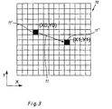
- the method according to the invention starts by defining a deformation or distortion direction by a single deformation vector 11 shown in FIG. 3 during an initialization phase in a source image 10 identified by a pixel matrix is determined, and this deformation vector 11 by a starting point 11 'with the starting point coordinates (x 0 , y 0 ) and an end point 11''with the end point coordinates (x 1 , y 1 ) is set and both the starting point 11' and the end point 11 "lie within the pixel matrix of the source image 10.
- This initialization phase is illustrated on the illustrated in Fig. 1 as grayscale photograph formed source image 10 with a projection of a deformation vector 11.
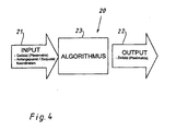
- FIG. 4 shows a basic flow diagram 20 of the method according to the invention, wherein the pixel matrix of the source image 10 and the coordinates of the starting point 11 'and the end point 11 "of the deformation vector 11 are input as input variables 21, while the output image 22 is the pixel matrix of the target image Transformation equation 23 is determined.
- the right-hand side of the transformation equation has as input variables 21 the respective pixels (x Q , y Q ) of the matrix of the source image 10 as well as the difference between the coordinates of the initial and End point (x 0 , y 0 ) or (x 1 , y 1 ) defined deformation vector 11 (x 1 - x 0 , y 1 - y 0 ) and a scaling factor F (x, y, K), while the left Side of the transformation equation as output variables 22 reproduces the respectively assigned pixels (x z , y z ) of the matrix of the target image; the scaling factor is in each case taken as the main diagonal element of a (2x2) matrix whose extradiagonal elements each have the zero, the product of the (2x2) matrix and the deformation vector 11 added to the coordinates of the respective source image pixel (x Q , y Q ) in each case corresponding target image pixels (x z , y z ) results.
- the scaling factor is in each case taken as the main
- the respective pixels of the source image 10 are shifted in the direction of the deformation vector 11 determined by the start point 11 'and the end point 11 "in accordance with their respective distances to the start and end points 11', 11".
- the degree of displacement or distortion depends on the scaling factor F (x, y, K) listed in the transformation equation, which essentially consists of the sum of the distances of the respective pixels to the start and end points 11 ', 11' 'in relation to Length of the deformation vector 11 is determined so that pixels in the immediate vicinity of the vector 11, ie to the start and end points, are subject to a greater shift than those pixels arranged at greater distances thereto, while pixels very far away from the deformation vector 11 remain virtually unshifted.
- FIG. 6 illustrates, in a contour line diagram 40, the functional profile of the scaling factor 31. From this diagram 40 it can be seen from a plurality of elliptically running height or equipotential lines 42, 42 ', 42 "that the scaling factor function 31 has an elliptical cross section.
- the foci 43, 43 'of such an ellipse coincide respectively with the beginning and end points 11' and 11 "of the deformation vector 11 together. Pixels lying on such an ellipse with starting point 11 'and end point 11 "of the deformation vector 11 as foci 43, 43' are shifted evenly.
- gaps resulting from the transformation are filled out. These gaps are regions in the target image 10 "in which no pixels or only very few pixels of the source image 10 have been imaged, so that these regions in the target image 10" have no correspondence in the source image 10. These regions of the target image 10 "are filled with newly generated pixels in this process step by determining transformed pixels arranged adjacent to these empty regions and determining, from their respectively assigned color density values for the newly generated pixels, the respectively corresponding color density values by interpolation be stored.
- Fig. 8 shows the target image 10 "in which this interpolation was performed; Due to the above-described properties of the scale factor function, the target image 10 "has round structures in the deformed regions, so that the process is advantageously suitable for representing natural shapes.
Landscapes
- Physics & Mathematics (AREA)
- General Physics & Mathematics (AREA)
- Engineering & Computer Science (AREA)
- Theoretical Computer Science (AREA)
- Image Processing (AREA)
Abstract
Claims (10)
- Procédé de traitement d'images pour l'affichage optique d'informations et/ou de signaux, une image source étant transformée en une image cible distordue ou déformée par rapport à celle-ci, caractérisé en ce qu'est défini, à l'intérieur de l'image source (10), un vecteur de déformation (11) définissant un sens de déformation et en ce qu'est déterminé, pour les pixels d'image respectifs de l'image source (10), respectivement une position de coordonnées correspondante dans l'image cible (10"), selon une règle de transformation (23) en dépendance fonctionnelle du vecteur de déformation (11) et d'un facteur d'échelle (31) qui tient compte de la position des pixels d'image respectifs en relation avec ce vecteur de déformation (11).
- Procédé de traitement d'images selon la revendication 1, caractérisé en ce qu'un tracé de fonction sensiblement elliptique est associé de telle manière au facteur d'échelle (31) que le vecteur de déformation (11) s'étend approximativement entre les foyers (43, 43') du tracé de fonction elliptique.
- Procédé de traitement d'images selon la revendication 1 ou 2, caractérisé en ce qu'est déterminée, pour chaque pixel d'image de l'image source (10), la valeur respectivement associée du facteur d'échelle (31), le facteur d'échelle (31) dépendant, pour l'essentiel, d'une part de la somme S = A0 + A1 formée à partir de la distance A0 entre le pixel d'image (x, y) respectif et le point de départ (11') du vecteur de déformation (11) désigné par les coordonnées (x0, y0) et de la distance A1 entre le pixel d'image respectif et le point final (11") du vecteur de déformation (11) désigné par les coordonnées (x1, y1) et, d'autre part, de la longueur L du vecteur de déformation (11).
- Procédé de traitement d'images selon la revendication 3, caractérisé en ce qu'est déterminée, pour chaque pixel d'image de l'image source (10), la valeur respectivement associée du facteur d'échelle (31) selon 1-((S-αL)/(αL)), α étant une constante ajustable, et, si la valeur respectivement déterminée est supérieure à zéro, cette valeur positive est affectée au pixel d'image respectif tandis que, dans le cas contraire, pour ce pixel d'image, la valeur du facteur d'échelle (31) est mise à zéro.
- Procédé de traitement d'images selon l'une des revendications 2 à 4, caractérisé en ce que les pixels d'image respectifs de l'image cible (10") sont déterminés à partir de la formation de la somme, pour chacune des coordonnées, des pixels d'image de l'image source (10) respectivement correspondants avec le produit, formé pour chacune des coordonnées, du facteur d'échelle respectivement déterminé (31) avec le vecteur de déformation (11).
- Procédé de traitement d'images selon l'une des revendications 2 à 5, caractérisé en ce qu'est définie, en tant que distance A0 entre le pixel d'image (x, y) respectif et le point de départ (11') du vecteur de déformation (11) désigné par les coordonnées (x0, y0) et en tant que distance A1 entre le pixel d'image respectif et son point final (11") désigné par les coordonnées (x1, y1), la relation A0 = ((x-x0)2 + (y-y0)2)½ resp. A1 = ((x-x1)2 + (y-y1)2)½.
- Procédé de traitement d'images selon l'une des revendications 1 à 6, caractérisé en ce que la longueur du vecteur de déformation (11) est calculée selon la relation L = ((x1-x0)2 + (y1-y0)2)½.
- Procédé selon l'une des revendications 1 à 7, caractérisé en ce que, dans l'image cible (10"), des positions vides qui se présentent en raison de la transformation sont comblées par des pixels d'image, nouvellement générés, par interpolation, à partir des valeurs respectives de la densité chromatique de pixels d'image voisins, de valeurs correspondantes de la densité chromatique pour les pixels d'image nouvellement générés.
- Dispositif permettant d'exécuter le procédé de traitement d'images, en particulier selon l'une des revendications 1 à 8, caractérisé en ce qu'est définissable, à l'intérieur de l'image source (10), un vecteur de déformation (11) définissant un sens de déformation et en ce qu'est déterminable, pour les pixels d'image respectifs de l'image source (10), respectivement une position de coordonnées correspondante dans l'image cible (10"), selon une règle de transformation (23) en dépendance fonctionnelle du vecteur de déformation (11) et d'un facteur d'échelle (31) qui tient compte de la position des pixels d'image respectifs en relation avec ce vecteur de déformation (11).
- Dispositif selon la revendication 9, caractérisé en ce que le facteur d'échelle (31) présente un tracé de fonction sensiblement elliptique, le vecteur de déformation (11) s'étendant approximativement entre les foyers (43, 43') du tracé de fonction elliptique.
Applications Claiming Priority (3)
| Application Number | Priority Date | Filing Date | Title |
|---|---|---|---|
| DE10120286 | 2001-04-25 | ||
| DE10120286 | 2001-04-25 | ||
| PCT/DE2002/001276 WO2002089059A2 (fr) | 2001-04-25 | 2002-04-08 | Procede de traitement d'image |
Publications (2)
| Publication Number | Publication Date |
|---|---|
| EP1386287A2 EP1386287A2 (fr) | 2004-02-04 |
| EP1386287B1 true EP1386287B1 (fr) | 2007-03-07 |
Family
ID=7682686
Family Applications (1)
| Application Number | Title | Priority Date | Filing Date |
|---|---|---|---|
| EP02740241A Expired - Lifetime EP1386287B1 (fr) | 2001-04-25 | 2002-04-08 | Procede de traitement d'image |
Country Status (4)
| Country | Link |
|---|---|
| US (1) | US20040156556A1 (fr) |
| EP (1) | EP1386287B1 (fr) |
| DE (1) | DE50209661D1 (fr) |
| WO (1) | WO2002089059A2 (fr) |
Families Citing this family (12)
| Publication number | Priority date | Publication date | Assignee | Title |
|---|---|---|---|---|
| US6765589B1 (en) | 2000-11-16 | 2004-07-20 | Adobe Systems Incorporated | Brush for warping and water reflection effects |
| US7312805B1 (en) | 2003-09-29 | 2007-12-25 | Adobe Systems Incorporated | User defined warping tool |
| GB2438668B (en) * | 2006-06-02 | 2008-07-30 | Siemens Molecular Imaging Ltd | Deformation of mask-based images |
| US7843467B2 (en) * | 2006-12-18 | 2010-11-30 | Microsoft Corporation | Shape deformation |
| GB2448168B (en) * | 2007-04-04 | 2009-08-26 | Siemens Medical Solutions | Method for interactive manual deformable registration |
| US8718133B2 (en) * | 2008-03-26 | 2014-05-06 | Samsung Electronics Co., Ltd. | Method and system for image scaling detection |
| US8165425B2 (en) * | 2008-07-24 | 2012-04-24 | Siemens Medical Solutions Usa, Inc. | Interactive manual deformable registration of images |
| US20140267425A1 (en) * | 2013-03-15 | 2014-09-18 | Crayola Llc | Personalized Digital Animation Kit |
| US9946448B2 (en) | 2013-03-15 | 2018-04-17 | Crayola Llc | Coloring kit for capturing and animating two-dimensional colored creation |
| US10475226B2 (en) | 2013-03-15 | 2019-11-12 | Crayola Llc | Coloring kit for capturing and animating two-dimensional colored creation |
| US10403029B2 (en) * | 2017-05-03 | 2019-09-03 | Microsoft Technology Licensing, Llc | Methods and systems for multistage post-rendering image transformation |
| CN112823375B (zh) * | 2018-11-09 | 2025-07-22 | 三星电子株式会社 | 使用前向扭曲、间隙鉴别器和基于坐标的修复的图像再合成 |
Family Cites Families (11)
| Publication number | Priority date | Publication date | Assignee | Title |
|---|---|---|---|---|
| EP0602730B1 (fr) * | 1992-12-18 | 2002-06-19 | Koninklijke Philips Electronics N.V. | Recalage d'images tridimensionnelles ayant des déformations élastiques relatives, à l'aide d'une correspondance de surfaces |
| US5636338A (en) * | 1993-01-29 | 1997-06-03 | Silicon Graphics, Inc. | Method for designing curved shapes for use by a computer |
| DE4316847A1 (de) * | 1993-05-19 | 1994-11-24 | Philips Patentverwaltung | Verfahren zum Entzerren von Röntgenaufnahmen und Anordnung zur Durchführung des Verfahrens |
| AU7603894A (en) * | 1993-08-27 | 1995-03-21 | Massachusetts Institute Of Technology | Example-based image analysis and synthesis using pixelwise correspondence |
| US5613013A (en) * | 1994-05-13 | 1997-03-18 | Reticula Corporation | Glass patterns in image alignment and analysis |
| US6288814B1 (en) * | 1994-05-19 | 2001-09-11 | Ortel Corporation | In-line predistorter for linearization of electronic and optical signals |
| DE4435183C2 (de) * | 1994-09-30 | 2000-04-20 | Siemens Ag | Verfahren zum Betrieb eines Magnetresonanzgeräts |
| US5731819A (en) * | 1995-07-18 | 1998-03-24 | Softimage | Deformation of a graphic object to emphasize effects of motion |
| GB2312123B (en) * | 1996-04-12 | 1999-01-13 | Discreet Logic Inc | Relocating picture points in response to manual operation of an interface device |
| US6807290B2 (en) * | 2000-03-09 | 2004-10-19 | Microsoft Corporation | Rapid computer modeling of faces for animation |
| US6963667B2 (en) * | 2001-01-12 | 2005-11-08 | National Instruments Corporation | System and method for signal matching and characterization |
-
2002
- 2002-04-08 US US10/476,067 patent/US20040156556A1/en not_active Abandoned
- 2002-04-08 DE DE50209661T patent/DE50209661D1/de not_active Expired - Fee Related
- 2002-04-08 EP EP02740241A patent/EP1386287B1/fr not_active Expired - Lifetime
- 2002-04-08 WO PCT/DE2002/001276 patent/WO2002089059A2/fr not_active Ceased
Also Published As
| Publication number | Publication date |
|---|---|
| US20040156556A1 (en) | 2004-08-12 |
| WO2002089059A2 (fr) | 2002-11-07 |
| WO2002089059A3 (fr) | 2003-05-30 |
| EP1386287A2 (fr) | 2004-02-04 |
| DE50209661D1 (de) | 2007-04-19 |
Similar Documents
| Publication | Publication Date | Title |
|---|---|---|
| DE60020887T2 (de) | Optischer fluss und bildaufbau | |
| DE69430336T2 (de) | Vergrösserung von digitalen Bildern mittels Kantenabbildung | |
| DE69623642T2 (de) | Vektorkorrelationssystem zum automatischen auffinden von mustern in einem bild | |
| EP1386287B1 (fr) | Procede de traitement d'image | |
| DE60000678T2 (de) | Optischer Scanner und zugehörige Software | |
| DE69029594T2 (de) | Ermittlung von Linienabschnitten und von vorbestimmten Mustern in einem optisch abgetasteten Dokument | |
| DE60009810T2 (de) | Antialiasing mit Abtastzeilen | |
| EP3427224B1 (fr) | Procédé, affichage tête haute, et système de restitution pour transformer en perspective et restituer un contenu d'image, et véhicule associé | |
| DE102004004641A1 (de) | Dreidimensionale Reprojektions- und Rückprojektionsverfahren und Algorithmen zum Durchführen derselben | |
| DE69330900T2 (de) | Verfahren zum Ausfüllen der Bildpunkte innerhalb eines Polygons | |
| DE69029429T2 (de) | Binäres Bildreduzierungsverfahren | |
| DE69529732T2 (de) | Korrektur der Perspektive von Texturen in graphischen Bildern durch adaptive Approximation | |
| DE69813931T2 (de) | Filterverfahren zur Fokussierung von Bildern | |
| EP2893510B1 (fr) | Procédé et processeur d'images pour eliminer un objet visuel d'un image | |
| DE102005046772A1 (de) | Iteratives Verfahren zur Interpolation von Bildinformationswerten | |
| DE69814011T2 (de) | Computergrafikverfahren und vorrichtung | |
| DE3837068B4 (de) | Bildverarbeitungsverfahren zur Gewinnung eines Schattenbildes | |
| EP1141883B1 (fr) | Procede de comparaison d'ensembles de points | |
| EP2187354B1 (fr) | Procédé de représentation de lignes continues | |
| DE102008048257B4 (de) | Verfahren zur Detektion eines Blockrasters | |
| EP1537538B1 (fr) | Procede de determination de facteurs de ponderation pour le calcul d'une valeur de couleur de texels pour une empreinte | |
| EP1537537A1 (fr) | Procede d'analyse et de modification d'une empreinte | |
| EP1397002B1 (fr) | Procédé d'interpolation des éléments d'image en fonction du gradient | |
| DE69325739T2 (de) | Grafisches System mit Anwendung von quadratischen Polynomelementen | |
| DE19703004A1 (de) | Verfahren zum Abbilden eines Quellenpixelbilds auf einen Zielpixelraum |
Legal Events
| Date | Code | Title | Description |
|---|---|---|---|
| PUAI | Public reference made under article 153(3) epc to a published international application that has entered the european phase |
Free format text: ORIGINAL CODE: 0009012 |
|
| 17P | Request for examination filed |
Effective date: 20031007 |
|
| AK | Designated contracting states |
Kind code of ref document: A2 Designated state(s): AT BE CH CY DE DK ES FI FR GB GR IE IT LI LU MC NL PT SE TR |
|
| AX | Request for extension of the european patent |
Extension state: AL LT LV MK RO SI |
|
| GRAP | Despatch of communication of intention to grant a patent |
Free format text: ORIGINAL CODE: EPIDOSNIGR1 |
|
| GRAS | Grant fee paid |
Free format text: ORIGINAL CODE: EPIDOSNIGR3 |
|
| GRAA | (expected) grant |
Free format text: ORIGINAL CODE: 0009210 |
|
| AK | Designated contracting states |
Kind code of ref document: B1 Designated state(s): DE FI GB |
|
| REG | Reference to a national code |
Ref country code: GB Ref legal event code: FG4D Free format text: NOT ENGLISH |
|
| PGFP | Annual fee paid to national office [announced via postgrant information from national office to epo] |
Ref country code: FI Payment date: 20070313 Year of fee payment: 6 |
|
| GBT | Gb: translation of ep patent filed (gb section 77(6)(a)/1977) |
Effective date: 20070307 |
|
| REF | Corresponds to: |
Ref document number: 50209661 Country of ref document: DE Date of ref document: 20070419 Kind code of ref document: P |
|
| PGFP | Annual fee paid to national office [announced via postgrant information from national office to epo] |
Ref country code: GB Payment date: 20070416 Year of fee payment: 6 |
|
| PLBE | No opposition filed within time limit |
Free format text: ORIGINAL CODE: 0009261 |
|
| STAA | Information on the status of an ep patent application or granted ep patent |
Free format text: STATUS: NO OPPOSITION FILED WITHIN TIME LIMIT |
|
| PG25 | Lapsed in a contracting state [announced via postgrant information from national office to epo] |
Ref country code: DE Free format text: LAPSE BECAUSE OF NON-PAYMENT OF DUE FEES Effective date: 20071101 |
|
| 26N | No opposition filed |
Effective date: 20071210 |
|
| GBPC | Gb: european patent ceased through non-payment of renewal fee |
Effective date: 20080408 |
|
| PG25 | Lapsed in a contracting state [announced via postgrant information from national office to epo] |
Ref country code: FI Free format text: LAPSE BECAUSE OF NON-PAYMENT OF DUE FEES Effective date: 20080408 |
|
| PG25 | Lapsed in a contracting state [announced via postgrant information from national office to epo] |
Ref country code: GB Free format text: LAPSE BECAUSE OF NON-PAYMENT OF DUE FEES Effective date: 20080408 |