EP1386643A1 - Snowboard, ski et fixation metallique de carre superieure - Google Patents
Snowboard, ski et fixation metallique de carre superieure Download PDFInfo
- Publication number
- EP1386643A1 EP1386643A1 EP02720460A EP02720460A EP1386643A1 EP 1386643 A1 EP1386643 A1 EP 1386643A1 EP 02720460 A EP02720460 A EP 02720460A EP 02720460 A EP02720460 A EP 02720460A EP 1386643 A1 EP1386643 A1 EP 1386643A1
- Authority
- EP
- European Patent Office
- Prior art keywords
- snowboard
- upper edge
- edge
- sole
- edges
- Prior art date
- Legal status (The legal status is an assumption and is not a legal conclusion. Google has not performed a legal analysis and makes no representation as to the accuracy of the status listed.)
- Granted
Links
Images


Classifications
-
- A—HUMAN NECESSITIES
- A63—SPORTS; GAMES; AMUSEMENTS
- A63C—SKATES; SKIS; ROLLER SKATES; DESIGN OR LAYOUT OF COURTS, RINKS OR THE LIKE
- A63C5/00—Skis or snowboards
- A63C5/03—Mono skis; Snowboards
-
- A—HUMAN NECESSITIES
- A63—SPORTS; GAMES; AMUSEMENTS
- A63C—SKATES; SKIS; ROLLER SKATES; DESIGN OR LAYOUT OF COURTS, RINKS OR THE LIKE
- A63C5/00—Skis or snowboards
- A63C5/03—Mono skis; Snowboards
- A63C5/033—Devices for enabling the use of a normal ski as mono-ski, e.g. platforms fixed on the ski for supporting the ski boots side-by-side
-
- A—HUMAN NECESSITIES
- A63—SPORTS; GAMES; AMUSEMENTS
- A63C—SKATES; SKIS; ROLLER SKATES; DESIGN OR LAYOUT OF COURTS, RINKS OR THE LIKE
- A63C5/00—Skis or snowboards
- A63C5/04—Structure of the surface thereof
- A63C5/048—Structure of the surface thereof of the edges
- A63C5/0485—Complementary or supplementary ski edges
-
- A—HUMAN NECESSITIES
- A63—SPORTS; GAMES; AMUSEMENTS
- A63C—SKATES; SKIS; ROLLER SKATES; DESIGN OR LAYOUT OF COURTS, RINKS OR THE LIKE
- A63C9/00—Ski bindings
- A63C9/003—Non-swivel sole plate fixed on the ski
-
- A—HUMAN NECESSITIES
- A63—SPORTS; GAMES; AMUSEMENTS
- A63C—SKATES; SKIS; ROLLER SKATES; DESIGN OR LAYOUT OF COURTS, RINKS OR THE LIKE
- A63C2203/00—Special features of skates, skis, roller-skates, snowboards and courts
- A63C2203/46—Skateboards or boards for snow having superimposed decks
Definitions
- the present invention relates to a snowboard and a ski each provided with upper edges above sole edges, and moreover relates to an upper edge fixture for fixing the upper edges on the snowboard and the ski.
- An object of the present invention is to provide a snowboard and a ski whose edges are not released easily even when being strongly engaged and which are easy to operate.
- a snowboard provided with sole edges along comer portions on both the left and right sides of a sliding surface comprises left and right upper edges respectively provided above the left and right sole edges so as to protrude more to the left and right sides of the snowboard than the left and right sole edges.
- a ski provided with sole edges along comer portions on both the left and right sides of a sliding surface comprises left and right-upper edges respectively provided above the left and right sole edges so as to protrude more to the left and right sides of the ski than the left and right sole edges.
- the left and right upper edges be tilted so that the ground contact angles of the left and right upper edges become smaller than the ground contact angles of the left and right sole edges. If so, the upper edge comes in contact with the snow surface at an angle smaller than the ground contact angle of the sole edge, whereby the tendency for the upper edge to be released reduces, and the snow surface can be easily caught.
- an upper edge fixture characterized by comprising upper edges provided on both the left and right sides of a fixture body which is overlappingly attached to an upper surface of a snowboard or a ski is provided.
- the upper edges can be easily attached to the snowboard or the ski.
- the upper edge fixture is equal to or shorter than the snowboard or the ski in length.
- FIG. 1 is a perspective view of a snowboard 1 according to an embodiment of the present invention.
- FIG. 2 is a sectional view taken along the line X-X in FIG. 1.
- Screw holes 9 for attaching a binding 40 described later are provided at plural positions of an upper surface 8 of the snowboard 1. By using these plural screw holes 9, the binding 40 can be attached to the upper surface 8 of the snowboard 1 in a desired position.
- a lower surface 10 of the snowboard 1 is a flat sliding surface and made of resin resistant to adhesion of snow.
- Sole edges 11 and 11 are provided along comer portions on both the left and right sides of the lower surface 10 (sliding surface).
- the sole edges 11 and 11 are formed of a hard material such as metal.
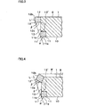
- a comer portion 11' of the sole edge 11 is formed to have almost a right angle (approximately 85° to approximately 90° ), a bottom surface 11a of the sole edge 11 is placed on the same plane with the lower surface of the snowboard 1, and in the shown example, similarly to a side surface 13 of the snowboard 1,. a side surface 11b of the sole edge 11 is formed on a plane which stands almost perpendicular to the bottom surface 11a of the sole edge 11.
- left and right upper edges 12 and 12 are provided, each being fixed to an upper portion of the side surface 13 of the snowboard 1.
- These left and right upper edges 12 and 12 are provided so as to protrude more to the left and right sides of the snowboard 1 than the sole edges 11--and 11 provided at the comer portions on both sides of the lower surface of the snowboard 1.
- a comer portion 12' of the upper edge 12 is also formed to have almost a right angle (approximately 85° to approximately 90° ), a bottom surface 12a of the upper edge 12 is placed parallel to the bottom surface 11a of the sole edge 11 and the lower surface 10 of the snowboard 1, and a side surface 12b of the upper edge 12 is formed parallel to the side surface 11b of the sole edge 11 and the side surface 13 of the snowboard 1 and on a plane which stands almost perpendicular to the bottom surface 12a of the upper edge 12.
- the upper edge 12 comes in contact with the snow surface at the ground contact angle ⁇ which is smaller than the ground contact angle ⁇ of the sole edge 11 when the snow surface is caught by both the comer portion 11' of the sole edge 11 and the comer portion 12' of the upper edge 12, whereby the tendency for the upper edge 12 to be released reduces, and the snow surface can be easily caught. As a result, it is more difficult to release the edge, and the operation of the snowboard 1 becomes more stable.
- the angle ⁇ by which the upper edge 12 is tilted upward be set so that the ground contact angle ⁇ of the upper edge 12 is approximately 45° when the snow surface is caught by both the comer portion 11' of the sole edge 11 and the comer portion 12' of the upper edge 12.
- FIGS. 3 and 4 Although the example in which the side surface 13 of the snowboard 1 is formed on the same plane with the side surface 11b of the sole edge 11 is shown in FIGS. 3 and 4, it is also possible to form the side surface 13 of the snowboard 1 at a concave surface which is recessed deeper to the inside than the side surface 11b of the sole edge 11 as written in FIGS. 3 and 4 by a dashed line 13'. In so doing, the tendency for snow to adhere to the side surface 13 of the snowboard 1 reduces, and strong edging can be continuously performed.
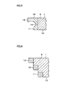
- the upper edge 12 is provided separately from the sole edge 11 is shown in any of FIGS 2 to 4, it is also suitable to attach an edge member 15 to the side surface 13 of the snowboard 1, form the upper edge 12 in an upper portion of the edge member 15, and form the sole edge 11 in a lower portion thereof as shown in FIG. 5.
- the upper edge 12 and the sole edge 11 may be provided integrally.
- one upper edge 12 is provided above the sole edge 11 in any of FIGS 2 to 5
- two upper edges 15 and 16 may be provided above the sole edge 11, for example, as shown in FIG. 6, and three upper edges 15, 16, and 17 may be provided above the sole edge 11, for example, as shown in FIG. 7.
- four or more upper edges may be provided above the sole edge 11.
- the upper edge provided above the sole edge 11 may be shorter than or equal to the sole edge 11 in length. Further, it is also possible to change the angle of the upper edge depending on its position. Furthermore, although the case where the binding 40 is attached to the upper surface 8 of the snowboard 1 by using the plural screw holes 9 provided in the upper surface 8 of the snowboard 1 is explained in FIG. 1, the present invention can be also applied to a case where the binding 40 is attached to the upper surface 8 of the snowboard 1 by using a rail provided on the upper surface 8 of the snowboard 1.
- FIG. 8 is a perspective view of a ski 2 according to an embodiment of the present invention.
- FIG. 9 is a sectional view taken along the line Y-Y in FIG. 8.
- a lower surface 20 is formed at a sliding surface, and sole edges 21 and 21 are provided along comer portions on the left and right sides of the lower surface 20.
- left and right upper edges 22 and 22 are respectively fixed to side surfaces of the ski 2 in such a manner to protrude more to the left and right sides of the ski 2 than the sole edges 21 and 21.
- the ski 2 thus structured according to the embodiment of the present invention, it is -possible to catch the snow surface by both the sole edge 21 and the upper edge 22 when edging is performed. Moreover, even when the ski 2 is excessively tilted and thereby the sole edge 21 is released, the snow surface can be caught by the upper edge 22 and the edge is not easily released even if the ski 2 is greatly tilted, whereby turning and braking can be performed easily without falling, which results in the stabilization of the operation of the ski 2.
- the ground contact angle of the sole edge 21 and the ground contact angle of the upper edge 22 may be the same, or the ground contact angle of the upper edge 22 may be smaller than the ground contact angle of the sole edge 21 by tilting the upper edge 22 upward.
- a side surface of the ski 2 may be formed at a concave surface which is recessed deeper to the inside than a side surface of the soled edge 21.
- the upper edge 22 may or may not protrude higher than an upper surface 19 of the ski 2.
- the upper edge 22 and the sole edge 21 may be provided integrally.
- two or more upper edges 21 may be provided above the sole edge 21.
- the upper edge provided above the sole edge 21 may be shorter or equal to the sole edge 21 in length.
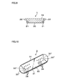
- FIG. 10 is a perspective view of an upper edge fixture 3 according to an embodiment of the present invention.
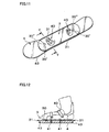
- FIG. 11 is a perspective view of a snowboard 4 on which the upper edge fixture 3 is mounted.
- the snowboard 4 shown in FIG. 11 is a heretofore publicly known snowboard (snowboard including only a sole edge 43 without including the upper edge which is characteristic of the present invention), which is different from the snowboard 1 explained previously in FIGS. 1, 2, and so on.
- the upper edge fixture 3 has a structure in which upper edges 31 and 31 are attached to both the left and right sides of a fixture body 30 which is slightly wider than the snowboard 4.
- a fixture body 30 which is slightly wider than the snowboard 4.
- holes 39 for passing screws therethrough when the binding 40 is attached to an upper surface of the snowboard 4 are provided at respective positions.
- the upper edge fixture 3 thus structured is overlappingly and closely attached to the upper surface of the snowboard 4.
- screw holes (not shown) for attaching the binding 40 are provided at plural positions of the upper surface of the snowboard 4.
- this upper edge fixture 3 If the thickness of this upper edge fixture 3 is increased, boots can be fitted at a high position from the upper surface of the snowboard 4, and consequently so-called lift up becomes possible. Moreover, it is also suitable to reduce the thickness of the upper edge fixture 3 or provide cut-outs, holes, or the like at appropriate intervals so as to give elasticity to the upper edge fixture 3. Further, by shifting the fixing position of the upper edge fixture 3 forward and backward on the upper surface of the snowboard 4, the upper edge 31 can be arranged in the front or in the rear.
- the front and rear portions of the upper edge fixture 3 may be recessed inward.
- the upper edge fixture 3 may be formed to have a rectangular shape as a whole with its front and rear portions formed in a linear shape.
- two or more upper edges may be provided.
- the upper edge may be shorter than or equal to the sole edge 43 in length. Additionally, the angle of the upper edge may be changed depending on its position.
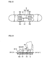
- FIG. 13 is a plan view of the snowboard 4 on which an upper edge fixture 5 according to another embodiment of the present invention is mounted.
- the snowboard 4 shown in FIG. 13 is the heretofore publicly known snowboard (snowboard including only a sole edge without including an upper edge).
- the upper edge fixture 5 of this embodiment includes two separate left and right fixture bodies 50 and 50, and upper edges 51 and 51 are respectively attached to outer surfaces of these fixture bodies 50 and 50.
- long holes 52 for passing screws therethrough when the binding 40 is attached to the upper surface of the snowboard 4 are provided at respective positions.
- the upper edges 51 and 51 can be provided to protrude above the sole edges of the lower surface of the snowboard 4.
- the long holes 52 are formed in the fixture bodies 50 and 50 as in the case of the upper edge fixture 5 explained in FIG. 13, it is possible to adjust the amount of protrusion of the upper edges 51 and 51 by changing the fixing positions of the fixture bodies 50 and 50 on the upper surface of the snowboard 4.
- the upper edge fixture 3 (5) when the upper edge fixture 3 (5) is attached to the upper surface of the snowboard 4, it is also suitable to lift up the upper edge fixture 3 (5) by placing a spacer 60 between the upper edge fixture 3 (5) and snowboard 4 as shown in FIG. 14.
- the use of such a spacer 60 facilitates the adjustment of the height of the upper edge.
- the binding 40 is attached to the upper surface of the snowboard 4 by the screws 41 in FIGS. 10 to 14, the present invention is also applicable to a case where the binding 40 is attached to the rail provided on the upper surface of the snowboard 1.
Landscapes
- Footwear And Its Accessory, Manufacturing Method And Apparatuses (AREA)
- Carpets (AREA)
- Materials Applied To Surfaces To Minimize Adherence Of Mist Or Water (AREA)
- Buildings Adapted To Withstand Abnormal External Influences (AREA)
Applications Claiming Priority (3)
| Application Number | Priority Date | Filing Date | Title |
|---|---|---|---|
| JP2001119650 | 2001-04-18 | ||
| JP2001119650A JP2002306665A (ja) | 2001-04-18 | 2001-04-18 | スノーボード,スキー板及びアッパーエッジ取付具 |
| PCT/JP2002/003812 WO2002085472A1 (fr) | 2001-04-18 | 2002-04-17 | Snowboard, ski et fixation metallique de carre superieure |
Publications (3)
| Publication Number | Publication Date |
|---|---|
| EP1386643A1 true EP1386643A1 (fr) | 2004-02-04 |
| EP1386643A4 EP1386643A4 (fr) | 2008-05-28 |
| EP1386643B1 EP1386643B1 (fr) | 2010-10-27 |
Family
ID=18969834
Family Applications (1)
| Application Number | Title | Priority Date | Filing Date |
|---|---|---|---|
| EP02720460A Expired - Lifetime EP1386643B1 (fr) | 2001-04-18 | 2002-04-17 | Snowboard avec carre supérieure |
Country Status (6)
| Country | Link |
|---|---|
| US (1) | US20040169349A1 (fr) |
| EP (1) | EP1386643B1 (fr) |
| JP (1) | JP2002306665A (fr) |
| AT (1) | ATE485878T1 (fr) |
| DE (1) | DE60238115D1 (fr) |
| WO (1) | WO2002085472A1 (fr) |
Cited By (4)
| Publication number | Priority date | Publication date | Assignee | Title |
|---|---|---|---|---|
| EP1637193A1 (fr) * | 2004-09-15 | 2006-03-22 | Gianfranco Elementi | Planche à plusieurs lames superposées |
| DE102006059332B4 (de) * | 2006-12-15 | 2010-01-07 | Gerda Wiesner | Gleitvorrichtung, insbesondere Ski oder Snowboard, und Verfahren zur Herstellung einer solchen Gleitvorrichtung |
| EP2517760A4 (fr) * | 2009-12-24 | 2014-02-26 | Ulf Morgan Friberg | Arêtes pour skis, snowboards et patins à glace |
| EP3045212A1 (fr) | 2015-01-19 | 2016-07-20 | Mojmir Flisek | Profil en coupe transversale de chant et carre |
Families Citing this family (5)
| Publication number | Priority date | Publication date | Assignee | Title |
|---|---|---|---|---|
| US20060091645A1 (en) * | 2004-10-15 | 2006-05-04 | Mervin Manufacturing, Inc. | Responsive transport board |
| US8075014B2 (en) * | 2007-10-04 | 2011-12-13 | Peter F. Phibbs | Snowboard or ski or the like having a channeled edge or multiple element edge |
| US20100013191A1 (en) * | 2008-07-15 | 2010-01-21 | Mckeever Nathaniel W | Performance enhanced snowboard |
| JP2011235047A (ja) * | 2010-04-30 | 2011-11-24 | Takechiyo Tachibana | ダブルエッヂスキ−板 |
| US20240245978A1 (en) * | 2023-01-20 | 2024-07-25 | Thomas F. Wheatley | One-Piece Edge Configuration for a Snowboard or a Ski |
Family Cites Families (13)
| Publication number | Priority date | Publication date | Assignee | Title |
|---|---|---|---|---|
| DE802500C (de) * | 1949-06-01 | 1951-02-12 | Carl Hailer | Schi mit Oberflaechenschutz |
| CH569493A5 (fr) * | 1972-06-08 | 1975-11-28 | Bildner Heinz | |
| DE7412359U (de) * | 1974-04-08 | 1975-10-23 | Jacobs M | Ski |
| DE2437944A1 (de) * | 1974-08-07 | 1976-02-19 | Max Jacobs | Zusatzkante fuer schis |
| JPS62174573A (ja) * | 1986-01-27 | 1987-07-31 | Toshiba Corp | 電子衝撃型イオン・スラスタ |
| JPS62174573U (fr) * | 1986-04-25 | 1987-11-06 | ||
| JPS6434081U (fr) * | 1987-08-24 | 1989-03-02 | ||
| US5083810A (en) * | 1991-01-22 | 1992-01-28 | Minidis James D | Dougle edge snow ski |
| US5303949A (en) * | 1993-04-26 | 1994-04-19 | Harper Luke J | Multi-edged downhill snow skis |
| DE9306333U1 (de) * | 1993-04-27 | 1993-09-02 | Hess, Eugen, 75305 Neuenbürg | Ski |
| US5580078A (en) * | 1993-11-12 | 1996-12-03 | Vance; Mark D. | Double-edged snowboard |
| EP1140295B1 (fr) * | 1999-01-07 | 2002-09-18 | Walter Stucki | Carres de securite pour skis et surfs de neige, skis et surfs de neige pourvus de tels carres de securite et procede de fabrication de tels skis et surfs de neige |
| US6866273B2 (en) * | 2000-12-08 | 2005-03-15 | The Burton Corporation | Sliding device |
-
2001
- 2001-04-18 JP JP2001119650A patent/JP2002306665A/ja active Pending
-
2002
- 2002-04-17 US US10/475,032 patent/US20040169349A1/en not_active Abandoned
- 2002-04-17 AT AT02720460T patent/ATE485878T1/de active
- 2002-04-17 DE DE60238115T patent/DE60238115D1/de not_active Expired - Lifetime
- 2002-04-17 EP EP02720460A patent/EP1386643B1/fr not_active Expired - Lifetime
- 2002-04-17 WO PCT/JP2002/003812 patent/WO2002085472A1/fr not_active Ceased
Cited By (4)
| Publication number | Priority date | Publication date | Assignee | Title |
|---|---|---|---|---|
| EP1637193A1 (fr) * | 2004-09-15 | 2006-03-22 | Gianfranco Elementi | Planche à plusieurs lames superposées |
| DE102006059332B4 (de) * | 2006-12-15 | 2010-01-07 | Gerda Wiesner | Gleitvorrichtung, insbesondere Ski oder Snowboard, und Verfahren zur Herstellung einer solchen Gleitvorrichtung |
| EP2517760A4 (fr) * | 2009-12-24 | 2014-02-26 | Ulf Morgan Friberg | Arêtes pour skis, snowboards et patins à glace |
| EP3045212A1 (fr) | 2015-01-19 | 2016-07-20 | Mojmir Flisek | Profil en coupe transversale de chant et carre |
Also Published As
| Publication number | Publication date |
|---|---|
| JP2002306665A (ja) | 2002-10-22 |
| ATE485878T1 (de) | 2010-11-15 |
| EP1386643A4 (fr) | 2008-05-28 |
| DE60238115D1 (de) | 2010-12-09 |
| US20040169349A1 (en) | 2004-09-02 |
| EP1386643B1 (fr) | 2010-10-27 |
| WO2002085472A1 (fr) | 2002-10-31 |
Similar Documents
| Publication | Publication Date | Title |
|---|---|---|
| US8262123B2 (en) | Snow riding implement | |
| US6722060B2 (en) | Snowboard boot | |
| CA2115825A1 (fr) | Systeme de fixation pour planches de glisse, particulierement les planches a neige; et bottes a utiliser avec ce systeme | |
| US20030094788A1 (en) | Magnetic snow equipment attachment system | |
| US6062586A (en) | Boot binding system for a snowboard | |
| EP1386643A1 (fr) | Snowboard, ski et fixation metallique de carre superieure | |
| US20050167933A1 (en) | Device for retaining a foot or boot on a sports apparatus | |
| US6253467B1 (en) | Mounting for a snowboard boot strap | |
| US20020153703A1 (en) | Snowboard binding system | |
| CN107148298A (zh) | 雪鞋 | |
| US20020153701A1 (en) | Snowboard binding system | |
| US20020153702A1 (en) | Snowboard binding system | |
| US20070138766A1 (en) | Device for receiving a foot or boot on a sports apparatus | |
| EP2616149B1 (fr) | Assemblage permettant de relier une botte à un ski et adaptateur devant être utilisé dans ledit assemblage | |
| US7287776B2 (en) | Snowboard binding | |
| US20020153704A1 (en) | Snowboard binding system | |
| US6530590B2 (en) | Snowboard binding system | |
| US8075003B2 (en) | Boot for use with a gliding board | |
| US10960290B2 (en) | Mounting system for snowboards and splitboards | |
| US20020153705A1 (en) | Snowboard binding system | |
| CA1239017A (fr) | Garniture de glissement pour le curling | |
| WO2003047707A3 (fr) | Ski | |
| EP1112760A1 (fr) | Protège-lame de patins | |
| JPH11342236A (ja) | スノーボード用バインディング装置 | |
| KR200320237Y1 (ko) | 인라인 스케이트용 빙판 스케이트 날 |
Legal Events
| Date | Code | Title | Description |
|---|---|---|---|
| PUAI | Public reference made under article 153(3) epc to a published international application that has entered the european phase |
Free format text: ORIGINAL CODE: 0009012 |
|
| 17P | Request for examination filed |
Effective date: 20031013 |
|
| AK | Designated contracting states |
Kind code of ref document: A1 Designated state(s): AT BE CH CY DE DK ES FI FR GB GR IE IT LI LU MC NL PT SE TR |
|
| A4 | Supplementary search report drawn up and despatched |
Effective date: 20080502 |
|
| 17Q | First examination report despatched |
Effective date: 20081021 |
|
| GRAP | Despatch of communication of intention to grant a patent |
Free format text: ORIGINAL CODE: EPIDOSNIGR1 |
|
| RTI1 | Title (correction) |
Free format text: SNOWBOARD WITH UPPER EDGE |
|
| GRAS | Grant fee paid |
Free format text: ORIGINAL CODE: EPIDOSNIGR3 |
|
| GRAA | (expected) grant |
Free format text: ORIGINAL CODE: 0009210 |
|
| AK | Designated contracting states |
Kind code of ref document: B1 Designated state(s): AT BE CH CY DE DK ES FI FR GB GR IE IT LI LU MC NL PT SE TR |
|
| REG | Reference to a national code |
Ref country code: GB Ref legal event code: FG4D |
|
| REG | Reference to a national code |
Ref country code: CH Ref legal event code: EP |
|
| REG | Reference to a national code |
Ref country code: IE Ref legal event code: FG4D |
|
| REF | Corresponds to: |
Ref document number: 60238115 Country of ref document: DE Date of ref document: 20101209 Kind code of ref document: P |
|
| REG | Reference to a national code |
Ref country code: NL Ref legal event code: VDEP Effective date: 20101027 |
|
| PG25 | Lapsed in a contracting state [announced via postgrant information from national office to epo] |
Ref country code: NL Free format text: LAPSE BECAUSE OF FAILURE TO SUBMIT A TRANSLATION OF THE DESCRIPTION OR TO PAY THE FEE WITHIN THE PRESCRIBED TIME-LIMIT Effective date: 20101027 Ref country code: SE Free format text: LAPSE BECAUSE OF FAILURE TO SUBMIT A TRANSLATION OF THE DESCRIPTION OR TO PAY THE FEE WITHIN THE PRESCRIBED TIME-LIMIT Effective date: 20101027 Ref country code: PT Free format text: LAPSE BECAUSE OF FAILURE TO SUBMIT A TRANSLATION OF THE DESCRIPTION OR TO PAY THE FEE WITHIN THE PRESCRIBED TIME-LIMIT Effective date: 20110228 Ref country code: FI Free format text: LAPSE BECAUSE OF FAILURE TO SUBMIT A TRANSLATION OF THE DESCRIPTION OR TO PAY THE FEE WITHIN THE PRESCRIBED TIME-LIMIT Effective date: 20101027 |
|
| PG25 | Lapsed in a contracting state [announced via postgrant information from national office to epo] |
Ref country code: GR Free format text: LAPSE BECAUSE OF FAILURE TO SUBMIT A TRANSLATION OF THE DESCRIPTION OR TO PAY THE FEE WITHIN THE PRESCRIBED TIME-LIMIT Effective date: 20110128 Ref country code: BE Free format text: LAPSE BECAUSE OF FAILURE TO SUBMIT A TRANSLATION OF THE DESCRIPTION OR TO PAY THE FEE WITHIN THE PRESCRIBED TIME-LIMIT Effective date: 20101027 |
|
| PG25 | Lapsed in a contracting state [announced via postgrant information from national office to epo] |
Ref country code: ES Free format text: LAPSE BECAUSE OF FAILURE TO SUBMIT A TRANSLATION OF THE DESCRIPTION OR TO PAY THE FEE WITHIN THE PRESCRIBED TIME-LIMIT Effective date: 20110207 |
|
| PG25 | Lapsed in a contracting state [announced via postgrant information from national office to epo] |
Ref country code: DK Free format text: LAPSE BECAUSE OF FAILURE TO SUBMIT A TRANSLATION OF THE DESCRIPTION OR TO PAY THE FEE WITHIN THE PRESCRIBED TIME-LIMIT Effective date: 20101027 |
|
| PLBE | No opposition filed within time limit |
Free format text: ORIGINAL CODE: 0009261 |
|
| STAA | Information on the status of an ep patent application or granted ep patent |
Free format text: STATUS: NO OPPOSITION FILED WITHIN TIME LIMIT |
|
| 26N | No opposition filed |
Effective date: 20110728 |
|
| REG | Reference to a national code |
Ref country code: DE Ref legal event code: R097 Ref document number: 60238115 Country of ref document: DE Effective date: 20110728 |
|
| PG25 | Lapsed in a contracting state [announced via postgrant information from national office to epo] |
Ref country code: MC Free format text: LAPSE BECAUSE OF NON-PAYMENT OF DUE FEES Effective date: 20110430 |
|
| REG | Reference to a national code |
Ref country code: CH Ref legal event code: PL |
|
| GBPC | Gb: european patent ceased through non-payment of renewal fee |
Effective date: 20110417 |
|
| PG25 | Lapsed in a contracting state [announced via postgrant information from national office to epo] |
Ref country code: CH Free format text: LAPSE BECAUSE OF NON-PAYMENT OF DUE FEES Effective date: 20110430 Ref country code: LI Free format text: LAPSE BECAUSE OF NON-PAYMENT OF DUE FEES Effective date: 20110430 |
|
| REG | Reference to a national code |
Ref country code: IE Ref legal event code: MM4A |
|
| PG25 | Lapsed in a contracting state [announced via postgrant information from national office to epo] |
Ref country code: GB Free format text: LAPSE BECAUSE OF NON-PAYMENT OF DUE FEES Effective date: 20110417 |
|
| PG25 | Lapsed in a contracting state [announced via postgrant information from national office to epo] |
Ref country code: IE Free format text: LAPSE BECAUSE OF NON-PAYMENT OF DUE FEES Effective date: 20110417 |
|
| PGFP | Annual fee paid to national office [announced via postgrant information from national office to epo] |
Ref country code: FR Payment date: 20120511 Year of fee payment: 11 |
|
| PGFP | Annual fee paid to national office [announced via postgrant information from national office to epo] |
Ref country code: IT Payment date: 20120428 Year of fee payment: 11 |
|
| PGFP | Annual fee paid to national office [announced via postgrant information from national office to epo] |
Ref country code: DE Payment date: 20120629 Year of fee payment: 11 |
|
| PGFP | Annual fee paid to national office [announced via postgrant information from national office to epo] |
Ref country code: AT Payment date: 20120420 Year of fee payment: 11 |
|
| PG25 | Lapsed in a contracting state [announced via postgrant information from national office to epo] |
Ref country code: LU Free format text: LAPSE BECAUSE OF NON-PAYMENT OF DUE FEES Effective date: 20110417 Ref country code: CY Free format text: LAPSE BECAUSE OF FAILURE TO SUBMIT A TRANSLATION OF THE DESCRIPTION OR TO PAY THE FEE WITHIN THE PRESCRIBED TIME-LIMIT Effective date: 20101027 |
|
| PG25 | Lapsed in a contracting state [announced via postgrant information from national office to epo] |
Ref country code: TR Free format text: LAPSE BECAUSE OF FAILURE TO SUBMIT A TRANSLATION OF THE DESCRIPTION OR TO PAY THE FEE WITHIN THE PRESCRIBED TIME-LIMIT Effective date: 20101027 |
|
| REG | Reference to a national code |
Ref country code: AT Ref legal event code: MM01 Ref document number: 485878 Country of ref document: AT Kind code of ref document: T Effective date: 20130430 |
|
| PG25 | Lapsed in a contracting state [announced via postgrant information from national office to epo] |
Ref country code: AT Free format text: LAPSE BECAUSE OF NON-PAYMENT OF DUE FEES Effective date: 20130430 Ref country code: DE Free format text: LAPSE BECAUSE OF NON-PAYMENT OF DUE FEES Effective date: 20131101 |
|
| REG | Reference to a national code |
Ref country code: FR Ref legal event code: ST Effective date: 20131231 |
|
| REG | Reference to a national code |
Ref country code: DE Ref legal event code: R119 Ref document number: 60238115 Country of ref document: DE Effective date: 20131101 |
|
| PG25 | Lapsed in a contracting state [announced via postgrant information from national office to epo] |
Ref country code: IT Free format text: LAPSE BECAUSE OF NON-PAYMENT OF DUE FEES Effective date: 20130417 Ref country code: FR Free format text: LAPSE BECAUSE OF NON-PAYMENT OF DUE FEES Effective date: 20130430 |