EP1386650A2 - Dispositif pour séparer une phase plus légère d'une eau usée. - Google Patents
Dispositif pour séparer une phase plus légère d'une eau usée. Download PDFInfo
- Publication number
- EP1386650A2 EP1386650A2 EP03017082A EP03017082A EP1386650A2 EP 1386650 A2 EP1386650 A2 EP 1386650A2 EP 03017082 A EP03017082 A EP 03017082A EP 03017082 A EP03017082 A EP 03017082A EP 1386650 A2 EP1386650 A2 EP 1386650A2
- Authority
- EP
- European Patent Office
- Prior art keywords
- separator
- fine
- stage
- separated
- lighter phase
- Prior art date
- Legal status (The legal status is an assumption and is not a legal conclusion. Google has not performed a legal analysis and makes no representation as to the accuracy of the status listed.)
- Granted
Links
- 239000002351 wastewater Substances 0.000 title claims description 76
- 238000003860 storage Methods 0.000 claims abstract description 68
- 238000000926 separation method Methods 0.000 claims abstract description 35
- 239000010802 sludge Substances 0.000 claims abstract description 19
- 238000004581 coalescence Methods 0.000 claims description 28
- 238000009423 ventilation Methods 0.000 claims description 5
- 239000000725 suspension Substances 0.000 claims 5
- 238000011010 flushing procedure Methods 0.000 claims 1
- 239000010865 sewage Substances 0.000 abstract description 4
- 239000006185 dispersion Substances 0.000 abstract description 3
- 239000007788 liquid Substances 0.000 description 28
- 238000007667 floating Methods 0.000 description 13
- 239000003921 oil Substances 0.000 description 9
- 230000000694 effects Effects 0.000 description 8
- 238000012423 maintenance Methods 0.000 description 8
- XLYOFNOQVPJJNP-UHFFFAOYSA-N water Substances O XLYOFNOQVPJJNP-UHFFFAOYSA-N 0.000 description 7
- 238000004140 cleaning Methods 0.000 description 5
- 239000013049 sediment Substances 0.000 description 5
- 238000009825 accumulation Methods 0.000 description 4
- 230000008901 benefit Effects 0.000 description 4
- 238000005345 coagulation Methods 0.000 description 4
- 230000015271 coagulation Effects 0.000 description 4
- 239000000463 material Substances 0.000 description 4
- 238000007789 sealing Methods 0.000 description 4
- 239000007787 solid Substances 0.000 description 4
- 230000004888 barrier function Effects 0.000 description 3
- 238000013461 design Methods 0.000 description 3
- 230000015654 memory Effects 0.000 description 3
- 239000000203 mixture Substances 0.000 description 3
- 230000001174 ascending effect Effects 0.000 description 2
- 230000001914 calming effect Effects 0.000 description 2
- 230000001419 dependent effect Effects 0.000 description 2
- 238000011161 development Methods 0.000 description 2
- 230000018109 developmental process Effects 0.000 description 2
- 238000005516 engineering process Methods 0.000 description 2
- 239000012530 fluid Substances 0.000 description 2
- 230000003993 interaction Effects 0.000 description 2
- 239000002480 mineral oil Substances 0.000 description 2
- 235000010446 mineral oil Nutrition 0.000 description 2
- 238000005457 optimization Methods 0.000 description 2
- 239000004576 sand Substances 0.000 description 2
- 238000004065 wastewater treatment Methods 0.000 description 2
- 238000011001 backwashing Methods 0.000 description 1
- 239000000356 contaminant Substances 0.000 description 1
- 230000008021 deposition Effects 0.000 description 1
- -1 dirt Substances 0.000 description 1
- 238000007599 discharging Methods 0.000 description 1
- 238000009826 distribution Methods 0.000 description 1
- 238000005243 fluidization Methods 0.000 description 1
- 238000007654 immersion Methods 0.000 description 1
- 230000001771 impaired effect Effects 0.000 description 1
- 239000010842 industrial wastewater Substances 0.000 description 1
- 238000003754 machining Methods 0.000 description 1
- 230000007257 malfunction Effects 0.000 description 1
- 238000004519 manufacturing process Methods 0.000 description 1
- 230000009347 mechanical transmission Effects 0.000 description 1
- 230000000704 physical effect Effects 0.000 description 1
- 238000003825 pressing Methods 0.000 description 1
- 230000000630 rising effect Effects 0.000 description 1
- 238000005070 sampling Methods 0.000 description 1
- 230000009182 swimming Effects 0.000 description 1
- 238000012360 testing method Methods 0.000 description 1
- 230000007704 transition Effects 0.000 description 1
- 238000011144 upstream manufacturing Methods 0.000 description 1
Images

Classifications
-
- E—FIXED CONSTRUCTIONS
- E03—WATER SUPPLY; SEWERAGE
- E03F—SEWERS; CESSPOOLS
- E03F5/00—Sewerage structures
- E03F5/14—Devices for separating liquid or solid substances from sewage, e.g. sand or sludge traps, rakes or grates
- E03F5/16—Devices for separating oil, water or grease from sewage in drains leading to the main sewer
-
- B—PERFORMING OPERATIONS; TRANSPORTING
- B01—PHYSICAL OR CHEMICAL PROCESSES OR APPARATUS IN GENERAL
- B01D—SEPARATION
- B01D17/00—Separation of liquids, not provided for elsewhere, e.g. by thermal diffusion
- B01D17/02—Separation of non-miscible liquids
- B01D17/0208—Separation of non-miscible liquids by sedimentation
-
- B—PERFORMING OPERATIONS; TRANSPORTING
- B01—PHYSICAL OR CHEMICAL PROCESSES OR APPARATUS IN GENERAL
- B01D—SEPARATION
- B01D17/00—Separation of liquids, not provided for elsewhere, e.g. by thermal diffusion
- B01D17/02—Separation of non-miscible liquids
- B01D17/0208—Separation of non-miscible liquids by sedimentation
- B01D17/0211—Separation of non-miscible liquids by sedimentation with baffles
-
- B—PERFORMING OPERATIONS; TRANSPORTING
- B01—PHYSICAL OR CHEMICAL PROCESSES OR APPARATUS IN GENERAL
- B01D—SEPARATION
- B01D17/00—Separation of liquids, not provided for elsewhere, e.g. by thermal diffusion
- B01D17/02—Separation of non-miscible liquids
- B01D17/0208—Separation of non-miscible liquids by sedimentation
- B01D17/0214—Separation of non-miscible liquids by sedimentation with removal of one of the phases
-
- B—PERFORMING OPERATIONS; TRANSPORTING
- B01—PHYSICAL OR CHEMICAL PROCESSES OR APPARATUS IN GENERAL
- B01D—SEPARATION
- B01D17/00—Separation of liquids, not provided for elsewhere, e.g. by thermal diffusion
- B01D17/02—Separation of non-miscible liquids
- B01D17/04—Breaking emulsions
- B01D17/045—Breaking emulsions with coalescers
-
- C—CHEMISTRY; METALLURGY
- C02—TREATMENT OF WATER, WASTE WATER, SEWAGE, OR SLUDGE
- C02F—TREATMENT OF WATER, WASTE WATER, SEWAGE, OR SLUDGE
- C02F1/00—Treatment of water, waste water, or sewage
- C02F1/40—Devices for separating or removing fatty or oily substances or similar floating material
Definitions
- the present invention relates to a separator system for separating a lighter one Phase and / or heavier components from a wastewater, in which over a Inlet the wastewater reaches a coarse separator stage, in which due to existing Density differences a large part of the easier phase of the wastewater and / or separate the heavier components of the wastewater, and one that is depleted Waste water then reaches a fine separator stage, where the rest of the mechanically dispersed lighter phase is separated from the waste water.
- Such a separator system is basically from wastewater disposal technology known where wastewater, often in large quantities during production and Machining processes are incurred, have to be prepared on site to make them to be able to discharge into the sewage system or into water in an environmentally friendly manner in this connection so-called light liquid separator systems represent an important group of Wastewater treatment plants, reliable due to the oily industrial wastewater be processed.
- water-insoluble organic Soiling such as oil and petrol, as well as a large number of solid contaminants removed from the waste water.
- the effect of a separator system is based on the fact that an easier phase like mineral oil, largely not physically dissolved in water, but as Dispersion is present.
- the two components are separated according to a certain one Time gravitationally, taking the lighter phase than drops to the wastewater surface rise and form a separate layer on the surface.
- a commonly used separator system consists of a sludge trap, an oil separator and possibly a coalescence separator. in the The sediments contained in the wastewater (dirt, sand, etc.). When the wastewater enters the sludge trap, the flow becomes for this slows down, causing solids that are heavier than wastewater to sink and collect on the bottom of the mud trap. Then this is done Separation of the lighter phase in the actual separator. This can also be a Coalescence separator must be connected downstream.
- the separator systems which correspond to DIN 1999 are state of the art. known in which the separated light liquid on the surface concentrated of the dispersion to be treated, usually no separate Light liquid storage is provided. As a result of backwater or at the end of the float the separated light liquid then rises in the shaft. Of Therefore, the separator systems known from the prior art must have a compared to the nearest drain installed shaft, or at Backwater can be provided with a downstream wastewater lifting plant. at Flooding of the separator system occurs here, the problem that no more the elevation of the shaft helps and the separated light fluid through the Gaps the cover of the separator system emerges.
- the transition is made to to integrate a separate oil storage chamber in the separator system, in which the separated light liquid by means of a skimmer or the like is derived.
- Such a separator system which complies with DIN 1999, may only be used installed with automatic termination, so that an unwanted escape of the separated lighter phase in the environment can be prevented.
- the automatic Graduation usually consists of a swimmer and an associated one Closing device of the separator drain.
- the DIN standard requires that the Separator with a separated amount of the lighter phase corresponding to 4/5 the amount of storage and the sludge trap when filling half the sludge trap content is emptied.
- the present invention is based on the problem described the task is based on a separator system of the type mentioned to further develop that, with simplified maintenance, the maximum storage volume at all times can be guaranteed for the separated lighter phase of the wastewater.
- the solution according to the invention has a number of essential advantages those known from wastewater disposal technology and explained above Separator systems.
- the collection container as one below open storage bell is constantly the maximum storage volume for the separated Lighter phase guaranteed, since subsequent water separation from the lighter phase does not reduce its storage volume.
- the waste water to be cleaned flows along their separately considered lighter phase and / or heavier components into the coarse separator stage and flows through the separator room. Act here sufficient dwell time the buoyancy and downforce and due to the existing Differences in density result in the separation process. In doing so, directly separable ones rise Components of the lighter phase immediately after the flow has calmed down Liquid surface and separate there. This happens in an advantageous manner Way in the front area of the downwardly open collection container. The heavier ones Components are deposited in the sludge trap. Forms in the storage bell there is a film of the lighter phase on the surface of the liquid, and that Depleted wastewater is continuously fed to the fine separator stage.
- the fine separator stage in which the rest the mechanically dispersed light phase coalesces, separated from the waste water and is added to the collection container, completely encapsulated and from the coarse separator stage is carried out separately. This occurs within the fine separator stage Separation of the lighter ones still remaining in the already depleted wastewater Phase of the wastewater by a coalescence treatment and the thereby separated lighter phase accumulates in the dome of the fine separator stage. This Components then enter, for example via a suitable return line the collecting tank while the cleaned wastewater flows off.
- the inlet over which the Waste water reaches the coarse separator stage opens below the storage bell.
- immediate, back-up-safe storage of the carried, freely separable lighter phase can be effected in the collecting container.
- On the Inlet which is realized, for example, via a lower dip tube, arrives the waste water under the storage bell in the sludge trap, so that the carried freely separable lighter phase rises and stored securely can be.
- Float lock provided.
- the float lock allows that over the fine separator inlet into the fine separator chamber permanently the depleted one Waste water is withdrawn from the surface of this.
- a possible realization could look like the float lock as an automatic Locking device with a tared tandem float with center Closure plate is executed. The tandem swimmer is outside of the fine separator inlet while a locking plate extends directly in the upper one Part of the fine separator inlet is guided.
- a float controlled Closure an automatically acting closure device is provided, whereby in a particularly advantageous manner the application is more complex and therefore vulnerable mechanical transmission units between the coarse separator stage and the fine separator stage can be avoided.
- the Float lock is integrated in the fine separator instead of it in the fine separator inlet to arrange.
- the flow in a preferred manner a depression is created in the system at the fine separator inlet. Based on this sink an angle is formed here, that of those floating on the free surface of the system Fine oil shares in the fine separator.
- a separator flap is provided, which in an outlet of the Fine separator stage comes into play.
- This end flap is advantageous Controlled by means of a float device, thus to a a particularly easy to implement particularly effective discharge of the separated prevent lighter phase.
- Solutions for controlling the end flap are conceivable.
- the separator system according to the invention one provided in the lower area of the fine separator stage, by a grid of has a separation chamber separate separator chamber.
- This division of Fine separator stage in a separation room located in the dome of the stage and in a separator chamber underneath provides a particularly easy to implement and it is a very effective design for the supplied depleted wastewater to be subjected to a coalescence treatment. This can be done with extremely little High wastewater treatment performance can be achieved.
- the separation of the Separation space from the separator chamber through a grid is also advantageous, since a coalescence bed can be formed in the separator chamber which separates the lighter phase from the depleted wastewater in the fine separator chamber.
- the coalescence bed has a filling from balls with a defined diameter and density. This has the advantage that the fine separator stage on waste water of different types or compositions can be optimally adjusted. This is done e.g. about an appropriate choice the ball filling for the coalescence bed in the separator chamber.
- the coalescence bed can be optimally adapted to the respective operating conditions. Of course you are here but other solutions are also conceivable.
- An advantageous implementation provides for the optimization of the volume flows of the wastewater entering the separator chamber is a vertical distributor plate or sheets is arranged. Through this particularly easy to implement and maintenance-free device can advantageously be as effective as possible Waste water coalescence treatment can be achieved. But of course other embodiments are also conceivable here.
- a Ball lock in a connection between the fine separator stage and the storage bell Rising pipe is provided to separate a return flow in the storage bell present lighter phase of the wastewater in the fine separator stage to prevent.
- This ball lock serves as an additional safety barrier, that works in the riser.
- an increase in pressure for example due to the accumulation of liquid in the separator system, is achieved by using the ball lock prepared without great mechanical effort that the already separated lighter phase emerges from the collective storage.
- the ball lock represents a particularly easy to implement safety barrier.
- the continuous and from the fill level of the collecting container independently feeding the lighter phase separated in the separation space to the a separated, lighter phase stored in the collecting container is a vertically movable one Outlet skimmer is provided at the storage bell end of the riser.
- the outlet of the riser pipe under the storage bell becomes vertical above it Movable floating outlet skimmer allows the ascending lighter phase always above the liquid surface under the storage bell exit.
- a short-circuit flow is thereby advantageously prevented this outlet skimmer is particularly easy to implement and can be used maintenance-free is.
- there is also another arrangement for feeding the lighter phase from the fine separator stage into the collection container is conceivable.
- the storage bell is one of the Has storage bell side from closing ventilation to a gas cushion in the to grant the upper area of the storage bell over the separated lighter phase.
- This gas cushion serves as an additional safety barrier at a Pressure increase in the separator system. Should namely because of a channel Backflow of the backwashing wastewater to pass through the fine separator Inlet and the one-sided float end in the coarse separator stage emerge, the liquid level in the entire container rises without this Storage capacity under the storage bell is impaired. Combined with the deep-drawn ventilation of the Storage bell always remains a gas cushion under this.
- the downward sealing ball lock prevents that the separated lighter phase also appears when the pressure rises further this way the fine separator stage can be pressed.
- the ball is in the floating position when open Passage. If the gas cushion reaches this locking device, the ball will sink and prevents gas passage. Due to the interaction ball lock-floating Outlet skimmer gas cushion is therefore particularly advantageous a double-acting locking device without great mechanical effort specified.
- the present invention is that in the storage bell Level sensor for level control is arranged.
- the advantages of such The arrangement lies particularly in the safe and trouble-free checking of the Fill the separated lighter phase in the storage bell to the point in time the need to empty the storage bell precisely.
- suction line is provided.
- This permanently installed suction line also serves in particular the usability and maintenance of the separator system to simplify.
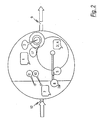
- FIG. 1 shows a cross-sectional side view of a preferred embodiment of the separator system according to the invention and Figure 2 is a corresponding plan view.
- the separator system consists of a coarse separator stage 100 and one downstream fine separator stage 101 together, which is completely encapsulated and is carried out separately from the coarse separator stage 100.
- a waste water arrives, which has a lighter phase and / or heavier components contains, in the coarse separator stage 100.
- a waste water is for example Mineral oil polluted waste water, in which sediments, such as dirt, sand or Mud are included.
- the lighter phase or the oil of the wastewater is largely in the wastewater not physically solved, but lies as a mixture of more or less large drops in front. Since oil (or the lighter phase) and the other phase of the wastewater one have different density, the two components after a certain Time separated gravitationally again, i.e. the easier phase increases in the form of droplets up to the surface and form a layer on it. The effect is based on this the coarse separator stage 100.
- the flow rate of the waste water is at the separator system according to the invention designed so that the residence time of this in the coarse separator stage 100 for the described separation of the oil (or lighter Phase) of the waste water is sufficient so that the content of the lighter phase in the depleted wastewater below the limit values specified in DIN 1999 lies.
- the coarse separator stage 100 consists of a storage bell 7, which acts as a collecting container serves the separated lighter phase, and a sludge trap room 1.
- Sludge trap 1 the sediments contained in the wastewater settle.
- the sludge trap 1 of the invention The separator system is coated accordingly from the inside, that it is completely oil-tight to prevent oil from escaping.
- the directly separable components of the lighter phase increase immediately after calming of the flow to the liquid surface and separate from there. This happens in the front area of the storage bell, which is open at the bottom 7th
- the space (1) below the storage bell (7), into which the inlet (12) opens, serves as a combined separation room for coarsely dispersed and thus directly separable Light liquid components and sediments. This causes the coarsely dispersed light liquid drops already deposited in this part. You climb inside the storage bell (7) and collect on the surface of the liquid. Serves at the same time the lower part of the room (1) as a sediment collecting room.
- the fine separator inlet 17 is additionally provided with an automatic closure device 2 in order to discharge to prevent the lighter phase separated in the coarse separator stage 100.
- the depleted wastewater then reaches the fine separator stage for coalescence treatment 101.
- This essentially has a separator chamber 3 and an im Dome of this arranged separation space 4.
- the separation space 4 is from the separator chamber 3 separated by a grid 13.
- the separator chamber 3 comprises a coalescence bed, which consists for example of a filling of spheres defined diameter and density. The dimensioning of these balls takes place depending on the wastewater to be treated. It is particularly advantageous that the inflow of the waste water into the separator chamber 3 via a swirl grid 14 takes place in order to swirl the wastewater and a corresponding fluidized bed to create. This can achieve that in the separator chamber 3 arranged coalescence bed is almost maintenance-free and self-cleaning.
- the separator chamber 3 For optimization the coalescence treatment by directing the volume flows of the depleted Waste water in the separator chamber 3 is a vertical distributor plate 19 in the separator chamber 3 is provided. Furthermore, the separator chamber 3 has a funnel-shaped design to herewith the swirling effect, which is generated via the vortex grid 14 by the funnel-shaped Favor enlargement of the flow cross-section.
- the fine separator stage 101 is characterized in that the optimal flow design in the Separator chamber 3 achieved coagulation effects and portions of the lighter phase in directly separable fractions are converted. In a zone of flow calming within the fine separator stage there is a direct separation separable components and their accumulation in its dome or in the separation room 4th
- the lighter phase separated in the fine separator stage 101 passes over a riser 5 in the storage bell 7 and is there with the already in the Coarse separator stage 101 separated lighter phase held back safe.
- the fine separator stage 101 is preceded by a coarse separator stage 100 there are no complicated separation and discharge devices available In the case of large loads of dirt, the lighter phase is derived into a separate one Memory can be disabled or ineffective. This allows none mechanical wear parts present in the separator system according to the invention are, which can be used almost maintenance-free in an advantageous manner.
- the lighter phase separated in the separation space 4 reaches the riser 5 into the storage bell 7.
- the outlet of the riser 5 under the storage bell manufactured using a vertically movable, floating outlet skimmer 6, so the ascending lighter phase is always above the liquid surface exits under the storage bell 7. This prevents a short-circuit flow.
- a safety shut-off in the form of a ball lock 18 also acts in the riser 5.
- a possible increase in pressure for example due to fluid build-up in the separator system, can be caused by backflow from the sewer network, i.e. from expiration 9 or from inflow 12, due to overloading or taking effect of the automatic float-controlled closure device 2 take place.
- Occurs Backflow from the sewer the backflowing waste water passes the fine separator stage 101 and passes through the fine separator inlet 17 and the one-way Float lock 2 in the coarse separator stage 100.
- the liquid level in the coarse separator stage 100 rises without the storage capacity below the Storage bell 7 is affected.
- the bottom ventilation 8 of the storage bell 7 always has a gas cushion 15 exist under this.
- the lighter phase collected under the storage bell 7, which can be backed up, can be by means of a suction line 11 can be removed separately almost without waste water.
- a Level control can also be carried out with a corresponding dipstick 10.
- the separator system shown in FIGS. 1 and 2 further comprises one at the bottom Part of the coarse separator chamber located self-holding outlet flap 16, which can be used to empty and rinse the coarse separator chamber 101. In the operating state, this flap 16 is closed and is additionally by itself forming sludge deposits at the bottom of the sludge trap 1 sealed.
- the essential points in the embodiment of the Separator systems according to the invention are that through the storage bell open at the bottom 7 basically contains a separated lighter phase, with a subsequent one Water separation from the lighter phase is not the storage volume of the Storage bell 7 reduced.
- the inlet 12 arranged below the storage bell 7 causes realized, for example, by means of a deep-drawn immersion tube, which is immediately secure against accumulation Storage of freely separable lighter phases carried in the wastewater.
- the lighter occurs only when the capacity of the storage bell 7 is exceeded Phase to the free liquid surface and does not secure another backed-up accident storage volume.
- the bottom edge of the storage bell is about 20 cm above the drain connection to the fine separator chamber One hundred and first
- the barrier-free riser 5 from the separation room 4 to the storage bell 7 ensures maintenance-free and trouble-free operation. A short circuit flow in the In the event of a malfunction, the floating outlet skimmer 6 remains Gas cushion 15 excluded under the storage bell 7 and the ball lock 11.
- an integrated sampling is also conceivable used in the separator system. It may also be a Rinsing connection on the upper part of the fine separator stage 101 makes sense. For surveillance the layer thickness of the separated lighter phase under the storage bell 7 and an alarm system could also be used to monitor the total separator be used.
- a coalescence bed in the separator chamber 3 would come a fluidized bed made of a plastic material in a spherical shape (4 to 5 cm in diameter) with a specific weight just above that of water in question, whereby the effect of the flow rate dependent coagulation with the independent coalescence.
- a fluidized bed made of a plastic material in a spherical shape (4 to 5 cm in diameter) with a specific weight just above that of water in question, whereby the effect of the flow rate dependent coagulation with the independent coalescence.
- a specific weight just above that of water in question
Landscapes
- Chemical Kinetics & Catalysis (AREA)
- Physics & Mathematics (AREA)
- Thermal Sciences (AREA)
- Chemical & Material Sciences (AREA)
- Life Sciences & Earth Sciences (AREA)
- Engineering & Computer Science (AREA)
- Hydrology & Water Resources (AREA)
- Public Health (AREA)
- Water Supply & Treatment (AREA)
- Health & Medical Sciences (AREA)
- Physical Water Treatments (AREA)
- Removal Of Floating Material (AREA)
- Separation Using Semi-Permeable Membranes (AREA)
Applications Claiming Priority (4)
| Application Number | Priority Date | Filing Date | Title |
|---|---|---|---|
| DE10234989 | 2002-07-31 | ||
| DE10234989 | 2002-07-31 | ||
| DE10244743 | 2002-09-25 | ||
| DE10244743A DE10244743B4 (de) | 2002-09-25 | 2002-09-25 | Abscheidersystem zum Abtrennen einer leichteren Phase aus einem Abwasser |
Publications (3)
| Publication Number | Publication Date |
|---|---|
| EP1386650A2 true EP1386650A2 (fr) | 2004-02-04 |
| EP1386650A3 EP1386650A3 (fr) | 2004-04-28 |
| EP1386650B1 EP1386650B1 (fr) | 2008-12-24 |
Family
ID=30116657
Family Applications (1)
| Application Number | Title | Priority Date | Filing Date |
|---|---|---|---|
| EP03017082A Expired - Lifetime EP1386650B1 (fr) | 2002-07-31 | 2003-07-28 | Dispositif pour séparer une phase plus légère d'une eau usée. |
Country Status (3)
| Country | Link |
|---|---|
| EP (1) | EP1386650B1 (fr) |
| AT (1) | ATE418372T1 (fr) |
| DE (1) | DE50310961D1 (fr) |
Cited By (1)
| Publication number | Priority date | Publication date | Assignee | Title |
|---|---|---|---|---|
| WO2006087575A3 (fr) * | 2005-02-18 | 2007-01-18 | Conder Products Ltd | Separateur huile/eau ameliore |
Families Citing this family (1)
| Publication number | Priority date | Publication date | Assignee | Title |
|---|---|---|---|---|
| DE102016113707B4 (de) * | 2016-07-26 | 2018-09-27 | MH Wassertechnologie GmbH | Verfahren und Vorrichtung zur Abscheidung von Flüssigkeitsphasen |
Citations (2)
| Publication number | Priority date | Publication date | Assignee | Title |
|---|---|---|---|---|
| EP0118021A2 (fr) | 1983-02-03 | 1984-09-12 | Nikolaus Hammerschmitt | Séparateur de liquides légers |
| EP0201072A2 (fr) | 1985-05-10 | 1986-11-12 | Nikolaus Hammerschmitt | Separateur de liquides légers |
Family Cites Families (4)
| Publication number | Priority date | Publication date | Assignee | Title |
|---|---|---|---|---|
| DE3014204A1 (de) * | 1979-12-19 | 1981-10-15 | Nikolaus 5350 Euskirchen Hammerschmitt | Verfahren und vorrichtung zum trennen oder abziehen eines gemisches aus leicht-, schwerfluessigkeit und ggf. schlamm |
| EP0037855A1 (fr) * | 1980-04-14 | 1981-10-21 | Nikolaus Hammerschmitt | Procédé et dispositif pour la séparation continue des composants d'un mélange de liquides de poids spécifiques différents |
| EP0308949B1 (fr) * | 1987-09-24 | 1993-09-08 | Nikolaus Hammerschmitt | Séparateur de liquides légers |
| AT399494B (de) * | 1993-12-13 | 1995-05-26 | Rat Rieder Abwassertechnik Ges | Schlamm- und ölabscheider |
-
2003
- 2003-07-28 EP EP03017082A patent/EP1386650B1/fr not_active Expired - Lifetime
- 2003-07-28 AT AT03017082T patent/ATE418372T1/de not_active IP Right Cessation
- 2003-07-28 DE DE50310961T patent/DE50310961D1/de not_active Expired - Fee Related
Patent Citations (2)
| Publication number | Priority date | Publication date | Assignee | Title |
|---|---|---|---|---|
| EP0118021A2 (fr) | 1983-02-03 | 1984-09-12 | Nikolaus Hammerschmitt | Séparateur de liquides légers |
| EP0201072A2 (fr) | 1985-05-10 | 1986-11-12 | Nikolaus Hammerschmitt | Separateur de liquides légers |
Cited By (1)
| Publication number | Priority date | Publication date | Assignee | Title |
|---|---|---|---|---|
| WO2006087575A3 (fr) * | 2005-02-18 | 2007-01-18 | Conder Products Ltd | Separateur huile/eau ameliore |
Also Published As
| Publication number | Publication date |
|---|---|
| EP1386650A3 (fr) | 2004-04-28 |
| ATE418372T1 (de) | 2009-01-15 |
| EP1386650B1 (fr) | 2008-12-24 |
| DE50310961D1 (de) | 2009-02-05 |
Similar Documents
| Publication | Publication Date | Title |
|---|---|---|
| EP0637653A2 (fr) | Dispositif de séparation de contaminants, notamment de contaminants bruts dans les installations de séparation pour la protection des plans d'eau | |
| EP0429593B1 (fr) | Separateur de liquides legers | |
| DE1642432B2 (de) | Klaer- und filteranlage | |
| DE202009010367U1 (de) | Vorrichtung zur Trennung von Regenwasser von chemisch, biologisch und/oder toxisch belasteten Abwässern | |
| EP1366245B1 (fr) | Installation d'epuration des eaux usees equipee d'un dispositif de purification | |
| DE60314894T2 (de) | Spülbecken mit ölgehaltrückgewinnungsfunktion | |
| DE202008012099U1 (de) | Verbesserter Schmutzwassereinlauf | |
| DE2544051A1 (de) | Reinigungsvorrichtung | |
| DE3124556C2 (de) | Verfahren zum Betrieb eines Leichtflüssigkeitsabscheiders für Abwasser und Leichtflüssigkeitsabscheider zu seiner Durchführung | |
| EP0201072A2 (fr) | Separateur de liquides légers | |
| DE3303632A1 (de) | Leichtfluessigkeitsabscheider | |
| EP0037855A1 (fr) | Procédé et dispositif pour la séparation continue des composants d'un mélange de liquides de poids spécifiques différents | |
| EP0069885B1 (fr) | Filtre à action séparatrice pour purifier de l'eau contaminée par un liquide léger tel qu'huile ou essence | |
| DE202007014331U1 (de) | Schmutzwassereinlauf | |
| DE202008017663U1 (de) | Straßeneinlauf (Gully) | |
| EP2157252A2 (fr) | Branchement ou siphon amélioré doté d'un dispositif de soutien pour liquides légers | |
| EP0824947B1 (fr) | Séparateur de liquides et dispositif de séparation incorporable dans celui-ci | |
| EP1386650B1 (fr) | Dispositif pour séparer une phase plus légère d'une eau usée. | |
| DE10244743B4 (de) | Abscheidersystem zum Abtrennen einer leichteren Phase aus einem Abwasser | |
| EP0820796A2 (fr) | Séparateur d'huile | |
| DE202009016167U1 (de) | Schmutzwassereinlauf mit Sicherung | |
| DE102019122938B4 (de) | Klärüberlauf und Durchlaufbecken | |
| EP1270055B1 (fr) | Séparateur de boues et d'huile pour eaux usées | |
| AT509469B1 (de) | Schwimmergesteuertes ventil | |
| EP0565483B1 (fr) | Bassin dans une installation d'eaux usées |
Legal Events
| Date | Code | Title | Description |
|---|---|---|---|
| PUAI | Public reference made under article 153(3) epc to a published international application that has entered the european phase |
Free format text: ORIGINAL CODE: 0009012 |
|
| AK | Designated contracting states |
Kind code of ref document: A2 Designated state(s): AT BE BG CH CY CZ DE DK EE ES FI FR GB GR HU IE IT LI LU MC NL PT RO SE SI SK TR |
|
| AX | Request for extension of the european patent |
Extension state: AL LT LV MK |
|
| PUAL | Search report despatched |
Free format text: ORIGINAL CODE: 0009013 |
|
| AK | Designated contracting states |
Kind code of ref document: A3 Designated state(s): AT BE BG CH CY CZ DE DK EE ES FI FR GB GR HU IE IT LI LU MC NL PT RO SE SI SK TR |
|
| AX | Request for extension of the european patent |
Extension state: AL LT LV MK |
|
| RIC1 | Information provided on ipc code assigned before grant |
Ipc: 7B 01D 17/00 B Ipc: 7B 01D 17/028 A Ipc: 7C 02F 1/40 B Ipc: 7B 01D 17/04 B Ipc: 7B 01D 17/032 B Ipc: 7B 01D 17/02 B Ipc: 7B 01D 17/025 B Ipc: 7E 03F 5/16 B |
|
| 17P | Request for examination filed |
Effective date: 20040910 |
|
| AKX | Designation fees paid |
Designated state(s): AT BE BG CH CY CZ DE DK EE ES FI FR GB GR HU IE IT LI LU MC NL PT RO SE SI SK TR |
|
| 17Q | First examination report despatched |
Effective date: 20070928 |
|
| GRAP | Despatch of communication of intention to grant a patent |
Free format text: ORIGINAL CODE: EPIDOSNIGR1 |
|
| GRAS | Grant fee paid |
Free format text: ORIGINAL CODE: EPIDOSNIGR3 |
|
| GRAA | (expected) grant |
Free format text: ORIGINAL CODE: 0009210 |
|
| AK | Designated contracting states |
Kind code of ref document: B1 Designated state(s): AT BE BG CH CY CZ DE DK EE ES FI FR GB GR HU IE IT LI LU MC NL PT RO SE SI SK TR |
|
| REG | Reference to a national code |
Ref country code: GB Ref legal event code: FG4D Free format text: NOT ENGLISH |
|
| REG | Reference to a national code |
Ref country code: CH Ref legal event code: EP |
|
| REG | Reference to a national code |
Ref country code: IE Ref legal event code: FG4D Free format text: LANGUAGE OF EP DOCUMENT: GERMAN |
|
| REF | Corresponds to: |
Ref document number: 50310961 Country of ref document: DE Date of ref document: 20090205 Kind code of ref document: P |
|
| PG25 | Lapsed in a contracting state [announced via postgrant information from national office to epo] |
Ref country code: FI Free format text: LAPSE BECAUSE OF FAILURE TO SUBMIT A TRANSLATION OF THE DESCRIPTION OR TO PAY THE FEE WITHIN THE PRESCRIBED TIME-LIMIT Effective date: 20081224 Ref country code: SI Free format text: LAPSE BECAUSE OF FAILURE TO SUBMIT A TRANSLATION OF THE DESCRIPTION OR TO PAY THE FEE WITHIN THE PRESCRIBED TIME-LIMIT Effective date: 20081224 Ref country code: NL Free format text: LAPSE BECAUSE OF FAILURE TO SUBMIT A TRANSLATION OF THE DESCRIPTION OR TO PAY THE FEE WITHIN THE PRESCRIBED TIME-LIMIT Effective date: 20081224 |
|
| NLV1 | Nl: lapsed or annulled due to failure to fulfill the requirements of art. 29p and 29m of the patents act | ||
| REG | Reference to a national code |
Ref country code: IE Ref legal event code: FD4D |
|
| PG25 | Lapsed in a contracting state [announced via postgrant information from national office to epo] |
Ref country code: ES Free format text: LAPSE BECAUSE OF FAILURE TO SUBMIT A TRANSLATION OF THE DESCRIPTION OR TO PAY THE FEE WITHIN THE PRESCRIBED TIME-LIMIT Effective date: 20090404 Ref country code: EE Free format text: LAPSE BECAUSE OF FAILURE TO SUBMIT A TRANSLATION OF THE DESCRIPTION OR TO PAY THE FEE WITHIN THE PRESCRIBED TIME-LIMIT Effective date: 20081224 Ref country code: RO Free format text: LAPSE BECAUSE OF FAILURE TO SUBMIT A TRANSLATION OF THE DESCRIPTION OR TO PAY THE FEE WITHIN THE PRESCRIBED TIME-LIMIT Effective date: 20081224 Ref country code: IE Free format text: LAPSE BECAUSE OF FAILURE TO SUBMIT A TRANSLATION OF THE DESCRIPTION OR TO PAY THE FEE WITHIN THE PRESCRIBED TIME-LIMIT Effective date: 20081224 Ref country code: BG Free format text: LAPSE BECAUSE OF FAILURE TO SUBMIT A TRANSLATION OF THE DESCRIPTION OR TO PAY THE FEE WITHIN THE PRESCRIBED TIME-LIMIT Effective date: 20090324 |
|
| PG25 | Lapsed in a contracting state [announced via postgrant information from national office to epo] |
Ref country code: SE Free format text: LAPSE BECAUSE OF FAILURE TO SUBMIT A TRANSLATION OF THE DESCRIPTION OR TO PAY THE FEE WITHIN THE PRESCRIBED TIME-LIMIT Effective date: 20090324 Ref country code: PT Free format text: LAPSE BECAUSE OF FAILURE TO SUBMIT A TRANSLATION OF THE DESCRIPTION OR TO PAY THE FEE WITHIN THE PRESCRIBED TIME-LIMIT Effective date: 20090525 Ref country code: CZ Free format text: LAPSE BECAUSE OF FAILURE TO SUBMIT A TRANSLATION OF THE DESCRIPTION OR TO PAY THE FEE WITHIN THE PRESCRIBED TIME-LIMIT Effective date: 20081224 |
|
| PG25 | Lapsed in a contracting state [announced via postgrant information from national office to epo] |
Ref country code: SK Free format text: LAPSE BECAUSE OF FAILURE TO SUBMIT A TRANSLATION OF THE DESCRIPTION OR TO PAY THE FEE WITHIN THE PRESCRIBED TIME-LIMIT Effective date: 20081224 |
|
| PG25 | Lapsed in a contracting state [announced via postgrant information from national office to epo] |
Ref country code: DK Free format text: LAPSE BECAUSE OF FAILURE TO SUBMIT A TRANSLATION OF THE DESCRIPTION OR TO PAY THE FEE WITHIN THE PRESCRIBED TIME-LIMIT Effective date: 20081224 |
|
| PLBE | No opposition filed within time limit |
Free format text: ORIGINAL CODE: 0009261 |
|
| STAA | Information on the status of an ep patent application or granted ep patent |
Free format text: STATUS: NO OPPOSITION FILED WITHIN TIME LIMIT |
|
| 26N | No opposition filed |
Effective date: 20090925 |
|
| BERE | Be: lapsed |
Owner name: ACO SEVERIN AHLMANN G.M.B.H. & CO. KG Effective date: 20090731 |
|
| PG25 | Lapsed in a contracting state [announced via postgrant information from national office to epo] |
Ref country code: MC Free format text: LAPSE BECAUSE OF NON-PAYMENT OF DUE FEES Effective date: 20090731 |
|
| REG | Reference to a national code |
Ref country code: CH Ref legal event code: PL |
|
| GBPC | Gb: european patent ceased through non-payment of renewal fee |
Effective date: 20090728 |
|
| REG | Reference to a national code |
Ref country code: FR Ref legal event code: ST Effective date: 20100331 |
|
| PG25 | Lapsed in a contracting state [announced via postgrant information from national office to epo] |
Ref country code: CH Free format text: LAPSE BECAUSE OF NON-PAYMENT OF DUE FEES Effective date: 20090731 Ref country code: LI Free format text: LAPSE BECAUSE OF NON-PAYMENT OF DUE FEES Effective date: 20090731 Ref country code: FR Free format text: LAPSE BECAUSE OF NON-PAYMENT OF DUE FEES Effective date: 20090731 |
|
| PG25 | Lapsed in a contracting state [announced via postgrant information from national office to epo] |
Ref country code: GB Free format text: LAPSE BECAUSE OF NON-PAYMENT OF DUE FEES Effective date: 20090728 |
|
| PG25 | Lapsed in a contracting state [announced via postgrant information from national office to epo] |
Ref country code: DE Free format text: LAPSE BECAUSE OF NON-PAYMENT OF DUE FEES Effective date: 20100202 Ref country code: BE Free format text: LAPSE BECAUSE OF NON-PAYMENT OF DUE FEES Effective date: 20090731 |
|
| PG25 | Lapsed in a contracting state [announced via postgrant information from national office to epo] |
Ref country code: GR Free format text: LAPSE BECAUSE OF FAILURE TO SUBMIT A TRANSLATION OF THE DESCRIPTION OR TO PAY THE FEE WITHIN THE PRESCRIBED TIME-LIMIT Effective date: 20090325 |
|
| PG25 | Lapsed in a contracting state [announced via postgrant information from national office to epo] |
Ref country code: AT Free format text: LAPSE BECAUSE OF NON-PAYMENT OF DUE FEES Effective date: 20090728 |
|
| PG25 | Lapsed in a contracting state [announced via postgrant information from national office to epo] |
Ref country code: IT Free format text: LAPSE BECAUSE OF FAILURE TO SUBMIT A TRANSLATION OF THE DESCRIPTION OR TO PAY THE FEE WITHIN THE PRESCRIBED TIME-LIMIT Effective date: 20081224 |
|
| PG25 | Lapsed in a contracting state [announced via postgrant information from national office to epo] |
Ref country code: LU Free format text: LAPSE BECAUSE OF NON-PAYMENT OF DUE FEES Effective date: 20090728 |
|
| PG25 | Lapsed in a contracting state [announced via postgrant information from national office to epo] |
Ref country code: HU Free format text: LAPSE BECAUSE OF FAILURE TO SUBMIT A TRANSLATION OF THE DESCRIPTION OR TO PAY THE FEE WITHIN THE PRESCRIBED TIME-LIMIT Effective date: 20090625 |
|
| PG25 | Lapsed in a contracting state [announced via postgrant information from national office to epo] |
Ref country code: TR Free format text: LAPSE BECAUSE OF FAILURE TO SUBMIT A TRANSLATION OF THE DESCRIPTION OR TO PAY THE FEE WITHIN THE PRESCRIBED TIME-LIMIT Effective date: 20081224 |
|
| PG25 | Lapsed in a contracting state [announced via postgrant information from national office to epo] |
Ref country code: CY Free format text: LAPSE BECAUSE OF FAILURE TO SUBMIT A TRANSLATION OF THE DESCRIPTION OR TO PAY THE FEE WITHIN THE PRESCRIBED TIME-LIMIT Effective date: 20081224 |