EP1386764A2 - Ventilateur centrifuge - Google Patents
Ventilateur centrifuge Download PDFInfo
- Publication number
- EP1386764A2 EP1386764A2 EP03254791A EP03254791A EP1386764A2 EP 1386764 A2 EP1386764 A2 EP 1386764A2 EP 03254791 A EP03254791 A EP 03254791A EP 03254791 A EP03254791 A EP 03254791A EP 1386764 A2 EP1386764 A2 EP 1386764A2
- Authority
- EP
- European Patent Office
- Prior art keywords
- scroll
- blower
- air
- enclosure
- suction port
- Prior art date
- Legal status (The legal status is an assumption and is not a legal conclusion. Google has not performed a legal analysis and makes no representation as to the accuracy of the status listed.)
- Withdrawn
Links
Images


Classifications
-
- B—PERFORMING OPERATIONS; TRANSPORTING
- B60—VEHICLES IN GENERAL
- B60H—ARRANGEMENTS OF HEATING, COOLING, VENTILATING OR OTHER AIR-TREATING DEVICES SPECIALLY ADAPTED FOR PASSENGER OR GOODS SPACES OF VEHICLES
- B60H1/00—Heating, cooling or ventilating devices
- B60H1/00457—Ventilation unit, e.g. combined with a radiator
- B60H1/00471—The ventilator being of the radial type, i.e. with radial expulsion of the air
-
- F—MECHANICAL ENGINEERING; LIGHTING; HEATING; WEAPONS; BLASTING
- F04—POSITIVE - DISPLACEMENT MACHINES FOR LIQUIDS; PUMPS FOR LIQUIDS OR ELASTIC FLUIDS
- F04D—NON-POSITIVE-DISPLACEMENT PUMPS
- F04D29/00—Details, component parts, or accessories
- F04D29/08—Sealings
- F04D29/083—Sealings especially adapted for elastic fluid pumps
-
- F—MECHANICAL ENGINEERING; LIGHTING; HEATING; WEAPONS; BLASTING
- F04—POSITIVE - DISPLACEMENT MACHINES FOR LIQUIDS; PUMPS FOR LIQUIDS OR ELASTIC FLUIDS
- F04D—NON-POSITIVE-DISPLACEMENT PUMPS
- F04D29/00—Details, component parts, or accessories
- F04D29/40—Casings; Connections of working fluid
- F04D29/42—Casings; Connections of working fluid for radial or helico-centrifugal pumps
- F04D29/4206—Casings; Connections of working fluid for radial or helico-centrifugal pumps especially adapted for elastic fluid pumps
- F04D29/4213—Casings; Connections of working fluid for radial or helico-centrifugal pumps especially adapted for elastic fluid pumps suction ports
-
- F—MECHANICAL ENGINEERING; LIGHTING; HEATING; WEAPONS; BLASTING
- F04—POSITIVE - DISPLACEMENT MACHINES FOR LIQUIDS; PUMPS FOR LIQUIDS OR ELASTIC FLUIDS
- F04D—NON-POSITIVE-DISPLACEMENT PUMPS
- F04D29/00—Details, component parts, or accessories
- F04D29/66—Combating cavitation, whirls, noise, vibration or the like; Balancing
- F04D29/661—Combating cavitation, whirls, noise, vibration or the like; Balancing especially adapted for elastic fluid pumps
- F04D29/663—Sound attenuation
Definitions
- the present invention relates to a centrifugal blower, for installation on a vehicle air conditioner or similar.
- Fig. 8 is a side sectional view of the conventional centrifugal blower
- Fig. 9 is a cross-sectional view in an arrow direction taken along the line A-A in Fig. 8
- Fig. 10 is a cross-sectional view in an arrow direction taken along the line B-B in Fig. 8.
- the centrifugal blower 1 includes a scroll 2 having a swirl shape, a suction port 3 formed on one side end surface 2a of the scroll 2, and a discharge port 4 formed at an end of winding of the scroll 2.
- the scroll 2 accommodates an impeller 5 having many blades 5a arranged in a circumferential direction around a rotating shaft 9, and an electrical motor 6 rotates the impeller 5. While the electrical motor 6 is driven electrically, air sucked from the suction port 4 flows toward an outside of the discharge port 4 via each spaces of the blades 5a.
- air blowing efficiency and specific noise of the centrifugal blower 1 are affected by pressure loss. That is, while the centrifugal blower 1 is driving in a state of high pressure loss, a part of the air (an arrow Ml of Fig. 8) discharged toward the discharge port 4 flows from the discharge port 4 toward the impeller 5, therefore, the efficiency of the blast of the centrifugal blower 1 goes down. At this time, part of air collides with the blades 5a, particularly a suction port side of the blades 5a because air sucked from the suction port 3 almost flows through the electrical motor side of the blades 5a, generating noise.
- a further part of the air is sucked again from a space between a suction port side end of the blades 5a and an inside surface of a bellmouth 3a of the suction port 3 into the impeller 5, therefore, disorderly airflow occurs by collision between air sucked afresh and air sucked again and low frequency noise is caused by the disorder of the airflow.
- a projection brim 7 is formed from a vicinity of a start of winding of the scroll 2 to a narrow passage portion that the distance between an outside circumference surface of the impeller 5 and an inside circumference surface of an outer circumference end surface 2b of the scroll 2 becomes narrow. Therefore, sucking force in the area that the backward flow air occurs and bypass dependent on the backward flow air goes down.
- the air blowing efficiency may go down because an opening size of the suction port 3 becomes smaller, that is, quantity of wind may reduce.
- disorder of airflow may occur because the opening shape of the suction port 3 is unbalanced with respect to the opening shape of the impeller 5. Therefore, the setting of the quantity of driven air may be complicated.
- the above invention does not solve the problem of noise from the backward flow air colliding with the suction port side of the blades 5a. Also backward flowing air may be sucked by even a small suction force because backward flow air immediately can get close to the space between the suction side end of the blades 5a and the inside surface of the bellmouth 3a of the suction port 3. Therefore, the above invention insufficiently attenuates to prevent backward flow air from bypassing. As a result, in such an invention, the problems outlined above may not be solved.
- a technical advantage of the present invention is that a lowering of an air blowing efficiency and of a specific noise may be reduced when the centrifugal blower is driving in a state of high pressure loss.
- a centrifugal blower in an embodiment of this invention, includes a scroll having a swirl shape and an impeller accommodated in the scroll.
- the impeller has many blades arranged in a circumferential direction around a rotating shaft.
- the scroll has a suction port formed on one side end surface of the scroll and a discharge port formed on an end of the winding of the scroll.
- the centrifugal blower sucks air from the suction port and discharges the air toward an outside of the discharge port via each space of the blades.
- An enclosure controls backward flow air discharged toward a vicinity of the discharge port.
- the enclosure is disposed at a circumferential direction around the suction port in the scroll. Such enclosure encloses an outside circumference of the impeller at regular intervals.
- a centrifugal blower for use in a vehicle air conditioner, according to the present invention is described.
- a centrifugal blower (hereinafter referred to as a blower) having many forward curved blades will be described as an example.
- Parts having like construction as in a conventional blower shown in Figs. 8 to 10 will be described using like reference numerals.
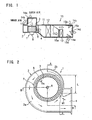
- a vehicle air conditioner 10 has an air conditioning duct 11 for introducing air-conditioning air.
- a blower 1 Toward the downwind side from the upwind side, there are installed a blower 1, an evaporator 12, which is a component of a refrigeration circuit, and a heater core 13 to which hot water is fed from a radiator (not shown) in order.
- each port 14a to 14e is controlled by open-close dampers 15a to 15d. Further, an amount of ventilation to the heater core 13 is controlled by an air mixing damper 15e.
- the blower 1 When air-cooling the interior of the vehicle compartment, the blower 1 is driven inner air or outer air passes through the evaporator 12 in which refrigerant is circulating to generate cold air and this cold air is discharged into the vehicle compartment at least through one of the discharge ports 14c to 14e.
- the blower 1 when air-heating the interior of the vehicle compartment, the blower 1 is likewise driven; inner air or outer air is caused to pass through the heater core 13 in which hot water is circulating to generate warm air; and this warm air is discharged into the vehicle compartment at least through one of the discharge ports 14c to 14e.
- the outline arrow of Fig. 1 indicates a flow of air.
- blower 1 adopts the following structure for improving the air blowing efficiency and the specific noise of the blower 1 in a state of a high pressure loss.
- the blower 1 includes a scroll 2 having a swirl shape and an impeller 5 accommodated in the scroll 2, and an electric motor 6 provided as a rotation drive source of the impeller 5.
- the impeller 5 has many forward curved blades 5a arranged in a circumferential direction around a rotating shaft 9.
- the scroll 2 has a suction port 3 formed on one side end surface 2a of the scroll 2 and a discharge port 4 formed on an end of winding of the scroll 2. While the electrical motor 6 is driven, air is sucked from the suction port 4 into the impeller 5 and the air sucked into the impeller 5 is discharged from discharge port 4 into the air conditioning duct 11 via each space of the blades 5a.
- blower 1 is similar to that of the conventional blower, and a feature of the blower 1 according to the invention resides in providing an enclosure 8 disposed around an outside circumference of the impeller 5 at regular intervals.
- the enclosure 8 integrally is formed on one side end surface 2a of the scroll 2 by resin founding and extending from an inside of the one side end surface 2a toward an electric motor direction.
- the enclosure 8 has a first width W1 and a second width W2 (W1>W2).
- the first width W1 (a projection portion 8a) extends from a vicinity of a start of a winding of the scroll 2 to a narrow passage portion becoming narrow at a distance between the outside circumference surface of the impeller 5 and an inside circumference surface of an outer circumference end surface 2b of the scroll 2. That is, the projection portion 8a is formed in correspond once with the area in the backward flow air easily occurs (a range L, in shown Fig. 2).
- the enclosure 8 prevents the backward flow from colliding with a suction port side of the blades 5a and sucking again from a space between a suction port side end of the blades 5a and an inside surface of a bellmouth 3a of the suction port 3 into the impeller 5. Moreover, the enclosure 8 still more prevents the above colliding and the above re-sucking because the projection portion 8a having the extensive width W1 is formed to correspond with the area that the backward flow air easily occurs.
- Fig. 5 comparing the conventional blower having no enclosure 8 with the blower 1 according to the invention.
- the ordinate axis shows sound pressure
- the abscissa axis shows frequency.
- the dotted parts in Fig. 5 show the amount of noise attenuation of the blower 1 according to the invention.
- low frequency noise in bands from 50 Hz to 160 Hz mainly caused by collision between air sucked afresh from the suction port 3 and air sucked again from the vicinity of the discharge port 4 via each spaces of the blades 5a into the impeller S is attenuated
- a high frequency noise in bands from 630 Hz to 16 kHz mainly caused by collision between the suction port side of the blades 5a and the backward flow air from the vicinity of the discharge port 4 is attenuated.
- Fig. 6 shows another projection portion 8b of the enclosure 8.
- the width of the projection portion 8b is extensively formed only on the start side of the winding of the scroll 2 and the width narrows going away from the start side of the winding of the scroll 2, because the backward flow air is concentrated at the start side of the winding of the scroll 2. Therefore, in this projection portion 8b, the above-mentioned noises may be attenuated.
- Fig. 7 shows another example of the blower 1. Parts having construction as in the above blower 1 will be described using like reference numerals.
- a feature of a blower 1 according to this example resides in providing a projection brim 7 as the conventional blower.
- the projection brim 7 is integrally formed at a part of a peripheral edge of the suction port 3 corresponding to the projection portion 8a. Therefore, there is increased prevention of the backward flow air return into the impeller 5 because of prevention of the sucking force in an area that backward flow air occurs easily.
Landscapes
- Engineering & Computer Science (AREA)
- Mechanical Engineering (AREA)
- General Engineering & Computer Science (AREA)
- Physics & Mathematics (AREA)
- Thermal Sciences (AREA)
- Structures Of Non-Positive Displacement Pumps (AREA)
Applications Claiming Priority (2)
| Application Number | Priority Date | Filing Date | Title |
|---|---|---|---|
| JP2002226299 | 2002-08-02 | ||
| JP2002226299A JP2004068644A (ja) | 2002-08-02 | 2002-08-02 | 遠心送風機 |
Publications (2)
| Publication Number | Publication Date |
|---|---|
| EP1386764A2 true EP1386764A2 (fr) | 2004-02-04 |
| EP1386764A3 EP1386764A3 (fr) | 2004-06-02 |
Family
ID=30112997
Family Applications (1)
| Application Number | Title | Priority Date | Filing Date |
|---|---|---|---|
| EP03254791A Withdrawn EP1386764A3 (fr) | 2002-08-02 | 2003-07-31 | Ventilateur centrifuge |
Country Status (2)
| Country | Link |
|---|---|
| EP (1) | EP1386764A3 (fr) |
| JP (1) | JP2004068644A (fr) |
Cited By (4)
| Publication number | Priority date | Publication date | Assignee | Title |
|---|---|---|---|---|
| US7883312B2 (en) | 2005-03-31 | 2011-02-08 | Mitsubishi Heavy Industries, Ltd. | Centrifugal blower |
| WO2014122016A1 (fr) * | 2013-02-08 | 2014-08-14 | Sulzer Pumpen Ag | Turbomachine et guide d'écoulement pour turbomachine |
| US9206817B2 (en) | 2010-08-31 | 2015-12-08 | Nippon Soken, Inc. | Centrifugal blower |
| FR3046958A1 (fr) * | 2016-01-22 | 2017-07-28 | Valeo Systemes Thermiques | Boitier d'entree d'air et installation de chauffage, ventilation et/ou climatisation pour vehicule automobile correspondante |
Families Citing this family (5)
| Publication number | Priority date | Publication date | Assignee | Title |
|---|---|---|---|---|
| JP4831811B2 (ja) * | 2005-03-31 | 2011-12-07 | 三菱重工業株式会社 | 遠心式送風装置 |
| KR101392784B1 (ko) * | 2008-09-19 | 2014-05-09 | 삼성전자주식회사 | 원심형 송풍기 |
| JP2012072758A (ja) * | 2010-09-01 | 2012-04-12 | Nippon Soken Inc | 遠心送風機 |
| JP7161654B2 (ja) * | 2018-02-28 | 2022-10-27 | サンデン株式会社 | 送風機 |
| WO2019167678A1 (fr) * | 2018-02-28 | 2019-09-06 | サンデンオートモーティブクライメイトシステム株式会社 | Soufflante |
Family Cites Families (4)
| Publication number | Priority date | Publication date | Assignee | Title |
|---|---|---|---|---|
| JPH09242696A (ja) * | 1996-03-11 | 1997-09-16 | Denso Corp | 遠心送風機 |
| AU6465398A (en) * | 1997-04-04 | 1998-10-30 | Bosch Automotive Systems Corporation | Centrifugal fan with flow control vanes |
| US5997246A (en) * | 1998-04-02 | 1999-12-07 | Ford Motor Company | Housing for a centrifugal blower |
| US6299409B1 (en) * | 1998-04-10 | 2001-10-09 | Denso Corporation | Centrifugal type blower unit |
-
2002
- 2002-08-02 JP JP2002226299A patent/JP2004068644A/ja active Pending
-
2003
- 2003-07-31 EP EP03254791A patent/EP1386764A3/fr not_active Withdrawn
Cited By (7)
| Publication number | Priority date | Publication date | Assignee | Title |
|---|---|---|---|---|
| US7883312B2 (en) | 2005-03-31 | 2011-02-08 | Mitsubishi Heavy Industries, Ltd. | Centrifugal blower |
| US9206817B2 (en) | 2010-08-31 | 2015-12-08 | Nippon Soken, Inc. | Centrifugal blower |
| US9447792B2 (en) | 2010-08-31 | 2016-09-20 | Denso Corporation | Centrifugal blower |
| WO2014122016A1 (fr) * | 2013-02-08 | 2014-08-14 | Sulzer Pumpen Ag | Turbomachine et guide d'écoulement pour turbomachine |
| CN105102823A (zh) * | 2013-02-08 | 2015-11-25 | 苏尔寿管理有限公司 | 流体机械和用于流体机械的导流元件 |
| US10634164B2 (en) | 2013-02-08 | 2020-04-28 | Sulzer Management Ag | Flow machine, and flow guiding element for a flow machine |
| FR3046958A1 (fr) * | 2016-01-22 | 2017-07-28 | Valeo Systemes Thermiques | Boitier d'entree d'air et installation de chauffage, ventilation et/ou climatisation pour vehicule automobile correspondante |
Also Published As
| Publication number | Publication date |
|---|---|
| JP2004068644A (ja) | 2004-03-04 |
| EP1386764A3 (fr) | 2004-06-02 |
Similar Documents
| Publication | Publication Date | Title |
|---|---|---|
| US6299409B1 (en) | Centrifugal type blower unit | |
| US6984111B2 (en) | Multiblade blower | |
| US6196013B1 (en) | Fan casing of window type air conditioner | |
| JP5333647B2 (ja) | ハニカムを有する暖房、換気、および空調のためのケース | |
| KR101152018B1 (ko) | 센터 마운팅 타입 차량 공조장치 | |
| JP3328985B2 (ja) | 空気調和装置 | |
| JP4682443B2 (ja) | 車両用空調装置 | |
| JP2004068644A (ja) | 遠心送風機 | |
| JP2000127740A (ja) | 遠心送風機 | |
| JPH1038305A (ja) | 天井埋込形空気調和機 | |
| JP3832009B2 (ja) | 遠心送風機 | |
| JPH0533797A (ja) | 押し込み式軸流フアン | |
| KR20000010434A (ko) | 자동차용 블로어 | |
| KR100339273B1 (ko) | 자동차 공조장치용 송풍장치 | |
| KR20210113958A (ko) | 차량용 공조장치의 송풍유닛 | |
| KR100679137B1 (ko) | 자동차 공조장치용 송풍기 | |
| US7930897B2 (en) | Window type air conditioner | |
| KR0160432B1 (ko) | 실내기의 스태빌라이져 | |
| KR20060094141A (ko) | 차량용 후석 공조장치 | |
| KR100364765B1 (ko) | 공기조화기 | |
| WO2005040686A2 (fr) | Climatiseur de type fenetre | |
| KR20240169931A (ko) | 차량용 공조장치 | |
| KR0121879B1 (ko) | 차량의 공조시스템 | |
| JP4081804B2 (ja) | 遠心式送風機、および車両用空調装置 | |
| KR20070025282A (ko) | 차량용 공조장치의 흡입구조 |
Legal Events
| Date | Code | Title | Description |
|---|---|---|---|
| PUAI | Public reference made under article 153(3) epc to a published international application that has entered the european phase |
Free format text: ORIGINAL CODE: 0009012 |
|
| AK | Designated contracting states |
Kind code of ref document: A2 Designated state(s): AT BE BG CH CY CZ DE DK EE ES FI FR GB GR HU IE IT LI LU MC NL PT RO SE SI SK TR |
|
| AX | Request for extension of the european patent |
Extension state: AL LT LV MK |
|
| PUAL | Search report despatched |
Free format text: ORIGINAL CODE: 0009013 |
|
| AK | Designated contracting states |
Kind code of ref document: A3 Designated state(s): AT BE BG CH CY CZ DE DK EE ES FI FR GB GR HU IE IT LI LU MC NL PT RO SE SI SK TR |
|
| AX | Request for extension of the european patent |
Extension state: AL LT LV MK |
|
| RIC1 | Information provided on ipc code assigned before grant |
Ipc: 7F 04D 29/66 B Ipc: 7F 04D 29/42 B Ipc: 7F 04D 29/16 B Ipc: 7B 60H 1/00 A |
|
| AKX | Designation fees paid | ||
| REG | Reference to a national code |
Ref country code: DE Ref legal event code: 8566 |
|
| STAA | Information on the status of an ep patent application or granted ep patent |
Free format text: STATUS: THE APPLICATION IS DEEMED TO BE WITHDRAWN |
|
| 18D | Application deemed to be withdrawn |
Effective date: 20041203 |