EP1386818A1 - Schiebetritt, insbesondere für Schienenfahrzeuge - Google Patents
Schiebetritt, insbesondere für Schienenfahrzeuge Download PDFInfo
- Publication number
- EP1386818A1 EP1386818A1 EP03015262A EP03015262A EP1386818A1 EP 1386818 A1 EP1386818 A1 EP 1386818A1 EP 03015262 A EP03015262 A EP 03015262A EP 03015262 A EP03015262 A EP 03015262A EP 1386818 A1 EP1386818 A1 EP 1386818A1
- Authority
- EP
- European Patent Office
- Prior art keywords
- sliding step
- step according
- cassette
- tread
- extension
- Prior art date
- Legal status (The legal status is an assumption and is not a legal conclusion. Google has not performed a legal analysis and makes no representation as to the accuracy of the status listed.)
- Granted
Links
Images

Classifications
-
- B—PERFORMING OPERATIONS; TRANSPORTING
- B60—VEHICLES IN GENERAL
- B60R—VEHICLES, VEHICLE FITTINGS, OR VEHICLE PARTS, NOT OTHERWISE PROVIDED FOR
- B60R3/00—Arrangements of steps or ladders facilitating access to or on the vehicle, e.g. running-boards
- B60R3/02—Retractable steps or ladders, e.g. movable under shock
-
- B—PERFORMING OPERATIONS; TRANSPORTING
- B61—RAILWAYS
- B61D—BODY DETAILS OR KINDS OF RAILWAY VEHICLES
- B61D23/00—Construction of steps for railway vehicles
- B61D23/02—Folding steps for railway vehicles, e.g. hand or mechanically actuated
- B61D23/025—Folding steps for railway vehicles, e.g. hand or mechanically actuated electrically or fluid actuated
Definitions
- the invention relates to a sliding step, in particular for rail vehicles, with a kickbox and one in the kickbox at least partially removable and slidably mounted Ausschub with a tread.
- the invention is a sliding step, especially for rail vehicles, be created, even in harsh environmental conditions has increased reliability.
- this is a sliding step, in particular for rail vehicles, with a kickbox and one in the kickbox at least partially removable and slidably mounted Ausschub provided with a tread, in which in the tread cassette sealed on all sides, against ingress of moisture and dirt sealed drying space is provided in which a drive motor and a control unit are arranged.
- the drive motor and the Control unit can be the engine, possibly required control electronics and electrical lines between the control unit and The drive motor can be arranged completely encapsulated.
- the Carrying out a drive shaft or drive rod is sealed executed.
- a very fail-safe Schiebetritt specifically for the very harsh environmental conditions for use in Rail vehicles is suitable.
- Supply and signal cables for the Drive motor and the control unit only need to be in the drying room be guided, with the introduction of these lines expediently also sealed.
- the drying space has at least one by means of a water-impermeable but permeable to water vapor Membrane closed vent on.
- the drying room is part of the kick cassette.
- the drive motor and the control unit can be fixed to the vehicle be arranged so that the connection of supply and Signal lines is facilitated.
- the Ausschub with a frame two side rails on, between which the drying room at least in the fully retracted position is arranged.
- the frame of the Ausschubs is moved in the tread cassette and there the drying room with the drive motor and the control unit between the side rails of the frame can be a very compact, nested structure of the Ausschubs, the drying room and the tread cassette are achieved.
- a shift in the Ausschubs can for example by means of a push chain and / or a Threaded spindle done.
- the Ausschub means of the two side rails guided in the pedal box.
- the Ausschub with a drive rod is coupled to that in the fully retracted End position of the extension at least in sections between the Side rails is arranged.
- a drive rod can For example, a rack, a threaded rod or a Push rod to be used.
- a drive rod is provided which with the Ausschub or the kick cassette by means of an elastic element coupled, and means are provided for deflection of the elastic element beyond a predefined threshold to detect.
- a safety mat By means of a safety mat, the entire tread surface can reliably Trittbelastüng be monitored.
- the function of a safety mat can for example, be adopted by an elastic element, at the deflection of a switch is actuated.
- the pedal cassette a extending substantially over its entire top kappbäre ⁇ Deckplätte.
- the sliding step for example for inspection or repair work, easily accessible in a simple way.
- the folding cover plate expediently works towards the vehicle interior towards.
- the cover plate forms a vehicle floor in the door area.
- the cover plate can for example, with a floor covering provided for the vehicle be pasted and is for example by means of Vorreibern in their closed Held position.
- the door cassette forms with the displaceable therein recorded Ausschub and the drive and control unit a replaceable module in the door area of a rail vehicle can be used in the floor. That way is the easily replaceable for repair, so that the duration of workshop stays can be reduced. About that In addition, the retrofitting of existing vehicles is facilitated.
- the kick cassette has a base plate and at least two opposite side walls, wherein the extension is slidably mounted on the side walls.
- the Trittkassette By the discharge directly in the side walls of the Trittkassette is stored, the Trittkassette can with transverse dimensions are executed, only by the thickness of the side walls as well of the space required for the guidance of the Ausschubs on the Transverse dimensions of Ausschubs lie.
- the tread is heated.
- the drive unit has an electrical DC motor with downstream planetary gear on and the drive unit drives a rack-and-pinion unit.
- Such a drive unit allows a very sensitive control and in particular collision detection of the Ausschubs by monitoring of the motor current.
- a transmission output shaft extends sealed through the wall of the drying room.
- the Drive unit and the Ausschub by means of an elastic element coupled.
- the drive unit with an electric provided activatable brake.
- Such a brake is advantageously flanged onto the motor shaft, arranged in the drying room and works on the working flow principle.
- the brake When the brake is energized, it brakes or blocks this the motor shaft, causing the ejection in each intermediate layer achieved is determinable.
- the one within a predefined Distance below and / or above the extension lying obstacle when over or under driving detect in the region of the front edge of the Ausschubs sensors provided, the one within a predefined Distance below and / or above the extension lying obstacle when over or under driving detect.
- sensors for example, spring-loaded switches or non-contact sensors, for example ultrasonic sensors or Diffuse reflection sensor, used.
- a in Fig. 1 in perspective illustrated sliding step 10 has a Trittkassette 12 and one, slidably mounted in the footstep cassette 12 Out 14 on.
- the Ausschub 14 can in through a Double arrow 16 indicated directions relative to the kick cassette 12th be moved.
- the Ausschub 14 in its substantially completely retracted into the kick cassette 12 Position shown.
- the kick cassette 12 is provided with a hinged cover plate 18, the essentially over the entire upper side of the tread cassette 12 extends.
- the cover plate 18 forms a floor section of a Rail vehicle, in which the sliding step 10 is used.
- the Cover plate 18 is by means not shown on the treadmill trumpet 12 locks. Due to the hinged cover plate 18, as shown in FIG. 1, the sliding step 10 for repair or inspection work very accessible. Close on three sides of the cover plate 18 Profile strips 20, which are firmly connected to the kick cassette 12 and create the transition to a floor of the rail vehicle.
- the profile strips 20 are interchangeably attached to the tread cassette 12, so that it causes noticeable wear caused by treading be exchanged by passengers.
- the cover plate 18 itself, for example, can be covered with a floor covering, which is also interchangeable when worn.
- a drying space 22 is provided which an electronic control unit 24, a drive motor 26 with an electrically activated Brake 27 and a terminal block 28 includes.
- the drying space 22 is provided with a lid, which in the illustration Fig. 1 is removed and not shown. It is also possible, the drying space 22 simultaneously with the closing of the cover plate 18 sealing closed.
- the drying room 22 is on one Base plate 30 of the pedal cassette 12 constructed and opposite to this thus immobile.
- Starting from the drive motor 26 extends a drive shaft 32 to a rack and pinion unit 34.
- Rack and pinion unit 34 becomes the extension 14 relative to the tread cassette 12 postponed.
- FIG. 2 shows the sliding step 10 when removed Cover plate 18.
- the Ausschub 14 is seen in his, in the extension direction front area provided with a step 36, the entire surface with a Safety mat is occupied. If the step 36 is thus extended in Condition burdened by passengers entering, will be any treading load detected by this switching mat and to the control unit 24 in the drying room 22 forwarded. Is by means of the safety mat a tread load the step 36 detected, for example, a Ausschubterrorism stopped immediately.
- the drive motor 26 in the drying room 22 is a permanent-magnet 24 volt DC motor with a downstream two-stage planetary gear and the flanged Hästrombremse 27 executed.
- the electrically activatable working current brake allows the drive motor 26 braked and stopped in any position become.
- the rack push unit 34 is via the output shaft 32nd driven and a rack 38 of the rack push unit 34th is guided by a frame 40 of Ausschubs 14 and points to the, the output shaft 32 opposite side of the frame 40 a Driver 42 on.
- the driver 42 is a not shown in FIG. 2 Spring pack supported against the frame 40. This spring package is deflected during a movement of the rack 38. Either when extending as well as pulling the Ausschubs 14 this spring package thus compressed or stretched.
- One in the area of the spring package arranged contact switch detects a compression or stretching the spring pack which has a predetermined threshold exceeds. If the spring package is more than the predetermined Threshold compressed or stretched, this detected information, provided on the control unit 24, which then for a predetermined distance the direction of movement of Ausschubs 14th reversed by suitable control of the drive motor 26.
- the Ausschub 14 is on two opposite side walls of Trittkassette 12 guided in guide rails 44.
- the guide rails are designed as a lot-bearing combination, so a possible height offset and angle error are recorded.
- In the guide profile rails 44 are each arranged two runners 46, which in turn are firmly connected to the Ausschub 14.
- the treads the guide rails 44 are through by the runners 46th arranged spring-loaded scrapers kept free of dirt.
- Each runner 46 has a total of three rollers. Two of these Casters are fixed, a third roller is designed as an eccentric.
- the Runners are placed in the guide rails with the fixed rollers in main loading direction 44 used. The third, executed as an eccentric Roll is turned against the main load direction, so that a backlash Run the rotor 46 is ensured in the guide rails 44.
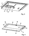
- the kick cassette 12 is taken out at Ausschub 14 and without the cover plate 18 shown.
- the sealed drying space 22 with the control unit 24, the drive motor 26 and distribution terminals 28.
- the drying room 22 is sealed against moisture and contamination and in the drying room 22 to be introduced connecting lines are introduced via tight fittings.
- In a back wall of the Dry space 22 are located for gas vent two through holes 49 with screw connections, in each of which a membrane is inserted is. It is essential that the membrane for closing the through holes 49 impermeable to water but permeable to water vapor is, so that caused by condensation in the drying room 22 Moisture can escape from this.
- vents serve generally for gas venting, but ensured is that neither dirt nor water in the drying room 22 can penetrate.
- the output shaft 32 in the area of their passage through a wall of the drying room 22 sealed.
- the Drying space 22 by means of a not shown in FIG. 3, separate Cover or sealed by the cover plate 18.
- the cover plate 18 itself is designed as a sandwich construction, so that a stable, yet lightweight cover arises.
- the cover plate 18 can be glued to the floor covering of the respective vehicle become.
- the Ausschub 14 is shown, the off having a welded construction, rectangular frame 40 has.
- the frame 40 consists of two side rails 50, on the outside thereof Side surfaces of the rotor 46 are arranged.
- the side rails 50 are via a rear cross-console 52 and at least over a front transverse console connected to each other, with the front Cross console in the illustration of FIG. 4 covered by the tread 36 and not recognizable.
- a robust plastic profile 54 provided to cover the front edge of the Frame 40 is subsequent to the tread 36.
- the rear seen in Ausschubraum Cross-console 52 has a central recess 56 for implementation the rack 38.
- the tread 36 is heated and to this Purpose with a heating cartridge in a pipe jacket and a thermostat provided, with the heating cartridges and the thermostat not shown are. Providing a thermostat ensures that the heater is switched on only when needed. The for the heating required power supply is available from the vehicle posed.
- the functions of the sliding step for example, extension as well coupled security functions are not directly dependent to the operational readiness of the heating, so that a failure of the Heating can not lead to a total failure of the sliding step.
- the sliding step 10 can be characterized as comparatively flat, be built replaceable module.
- the kick cassette 12 is in a simple manner from the base plate 30 and the attached on three sides Sidewalls formed.
- the side walls consist of Extrusions.
Landscapes
- Engineering & Computer Science (AREA)
- Mechanical Engineering (AREA)
- Power-Operated Mechanisms For Wings (AREA)
Abstract
Description
- Fig. 1
- eine perspektivische Ansicht eines erfindungsgemäßen Schiebetritts für ein Schienenfahrzeug mit aufgeklappter Deckplatte,
- Fig. 2
- eine weitere perspektivische Ansicht des Schiebetritts der Fig. 1 bei abgenommener Deckplatte,
- Fig. 3
- eine perspektivische Ansicht der Trittkassette des Schiebetritts der Fig. 1 und
- Fig. 4
- eine perspektivische Ansicht des Ausschubs des Schiebetritts der Fig. 1.
Claims (15)
- Schiebetritt, insbesondere für Schienenfahrzeuge, mit einer Trittkassette (12) und einem in der Trittkassette (12) wenigstens abschnittsweise aufnehmbaren und verschiebbar gelagerten Ausschub (14) mit einer Trittfläche (36), dadurch gekennzeichnet, dass innerhalb der Trittkassette (12) ein allseitig abgeschlossener, gegen eindringende Feuchtigkeit und Verschmutzung abgedichteter Trockenraum (22) vorgesehen ist, in dem ein Antriebsmotor (26) und eine Steuereinheit (24) angeordnet sind.
- Schiebetritt nach Anspruch 1, dadurch gekennzeichnet, dass der Trockenraum (22) wenigstens eine mittels einer wasserundurchlässigen aber wasserdampfdurchlässigen Membran verschlossene Entlüftungsöffnung aufweist.
- Schiebetritt nach einem der vorstehenden Ansprüche, dadurch gekennzeichnet, dass der Trockenraum (22) Bestandteil der Trittkassette (12) ist.
- Schiebetritt nach einem der vorstehenden Ansprüche, dadurch gekennzeichnet, dass der Ausschub (14) einen Rahmen (40) mit zwei Seitenholmen (50) aufweist, zwischen denen der Trockenraum (22) wenigstens in der vollständig eingefahrenen Stellung des Ausschubs (14) angeordnet ist.
- Schiebetritt nach Anspruch 4, dadurch gekennzeichnet, dass der Ausschub (14) mittels der beiden Seitenholme (30) in der Trittkassette (12) geführt ist.
- Schiebetritt nach Anspruch 4 oder 5, dadurch gekennzeichnet, dass der Ausschub (14) mit einer Antriebsstange (38) gekoppelt ist, die in der vollständig eingefahrenen Endstellung des Ausschubs (14) wenigstens abschnittsweise zwischen den Seitenholmen (50) angeordnet ist.
- Schiebetritt nach einem der vorstehenden Ansprüche, dadurch gekennzeichnet, dass eine Antriebsstange (38) vorgesehen ist, die mit dem Ausschub (14) oder der Trittkassette (12) mittels eines elastischen Elements gekoppelt ist, und dass Mittel vorgesehen sind, um eine Auslenkung des elastischen Elements über einen vordefinierten Schwellwert hinaus zu detektieren.
- Schiebetritt nach einem der vorstehenden Ansprüche, dadurch gekennzeichnet, dass der Ausschub (14) im Bereich der Trittfläche (36) mit einer Schaltmatte belegt ist.
- Schiebetritt nach einem der vorstehenden Ansprüche, dadurch gekennzeichnet, dass die Trittkassette (12) eine sich im wesentlichen über ihre gesamte Oberseite erstreckende klappbare Deckplatte (18) aufweist.
- Schiebetritt nach Anspruch 9, dadurch gekennzeichnet, dass die Deckplatte (18) einen Fahrzeugfußboden im Türbereich bildet.
- Schiebetritt nach einem der vorstehenden Ansprüche, dadurch gekennzeichnet, dass die Trittkassette (12) mit dem darin verschiebbar aufgenommenen Ausschub (14) sowie dem Antriebsmotor (26) und der Steuereinheit (24) ein austauschbares Modul bilden, das im Türbereich eines Schienenfahrzeugs in dessen Fußboden einsetzbar ist.
- Schiebetritt nach einem der vorstehenden Ansprüche, dadurch gekennzeichnet, dass die Trittkassette (12) eine Grundplatte (30) und wenigstens zwei gegenüberliegende Seitenwandungen aufweist, wobei der Ausschub (14) verschiebbar an den Seitenwandungen gelagert ist.
- Schiebetritt nach einem der vorstehenden Ansprüche, dadurch gekennzeichnet, dass die Trittfläche (36) beheizbar ist.
- Schiebetritt nach einem der vorstehenden Ansprüche, dadurch gekennzeichnet, dass als Antriebsmotor (26) ein elektrischer Gleichstrommotor mit nachgeschaltetem Planetengetriebe vorgesehen ist, der eine Zahnstangenschubeinheit (34) antreibt.
- Schiebetritt nach einem der vorstehenden Ansprüche, dadurch gekennzeichnet, dass der Antriebsmotor (26) mit einer elektrisch aktivierbaren Bremse versehen ist.
Applications Claiming Priority (2)
| Application Number | Priority Date | Filing Date | Title |
|---|---|---|---|
| DE10235871A DE10235871A1 (de) | 2002-07-31 | 2002-07-31 | Schiebetritt |
| DE10235871 | 2002-07-31 |
Publications (2)
| Publication Number | Publication Date |
|---|---|
| EP1386818A1 true EP1386818A1 (de) | 2004-02-04 |
| EP1386818B1 EP1386818B1 (de) | 2005-04-27 |
Family
ID=30010607
Family Applications (1)
| Application Number | Title | Priority Date | Filing Date |
|---|---|---|---|
| EP03015262A Expired - Lifetime EP1386818B1 (de) | 2002-07-31 | 2003-07-07 | Schiebetritt, insbesondere für Schienenfahrzeuge |
Country Status (3)
| Country | Link |
|---|---|
| EP (1) | EP1386818B1 (de) |
| DE (2) | DE10235871A1 (de) |
| ES (1) | ES2240890T3 (de) |
Cited By (5)
| Publication number | Priority date | Publication date | Assignee | Title |
|---|---|---|---|---|
| WO2010072585A1 (de) | 2008-12-15 | 2010-07-01 | Bombardier Transportation Gmbh | Schiebetrittanordnung für ein schienenfahrzeug |
| WO2012076048A1 (de) * | 2010-12-08 | 2012-06-14 | Gebr. Bode Gmbh & Co. Kg | Ein-/ausstiegsausschub mit bremsmitteln |
| EP2602167A1 (de) | 2011-12-08 | 2013-06-12 | Bombardier Transportation GmbH | Schiebetrittanordnung für ein Schienenfahrzeug |
| CN110077323A (zh) * | 2019-04-13 | 2019-08-02 | 江苏永迈汽车科技有限公司 | 一种抽屉式的汽车智能踏板 |
| EP3812234A1 (de) * | 2019-10-21 | 2021-04-28 | Bombardier Transportation GmbH | Trittvorrichtung für ein personentransportfahrzeug und personentransportfahrzeug |
Families Citing this family (6)
| Publication number | Priority date | Publication date | Assignee | Title |
|---|---|---|---|---|
| DE102005057901B4 (de) * | 2005-12-02 | 2007-10-04 | Siemens Ag | Schienenfahrzeug mit im Einstiegsbereich angeordnetem Schiebetritt |
| CN103847756B (zh) * | 2012-12-07 | 2017-04-19 | 庞巴迪运输有限公司 | 用于轨道车辆的可伸缩式台阶装置 |
| DE102014210783A1 (de) * | 2014-06-05 | 2015-12-17 | Siemens Aktiengesellschaft | Schiebetritt-Gehäuse für ein Schienenfahrzeug |
| CN105035104A (zh) * | 2015-09-18 | 2015-11-11 | 成都明日星辰科技有限公司 | 一种用于轨道交通的机械耐用式智能踏板 |
| CN105620510B (zh) * | 2015-12-08 | 2018-07-24 | 金鹰重型工程机械有限公司 | 一种车载限界检测设备安装机构 |
| DE202018106885U1 (de) | 2018-12-04 | 2020-03-05 | Gebr. Bode Gmbh & Co. Kg | Trittsystem für ein Fahrzeug |
Citations (6)
| Publication number | Priority date | Publication date | Assignee | Title |
|---|---|---|---|---|
| EP0118923A2 (de) * | 1983-03-14 | 1984-09-19 | Heinrich Bald Fahrzeugfabrik GmbH & Co. | Ausfahrbare Trittstufe für Kraftfahrzeuge oder dergleichen |
| FR2670445A1 (fr) * | 1990-09-28 | 1992-06-19 | France Ste Expl Ets Marcel | Marchepied electriquement deployable et escamotable. |
| US5775232A (en) * | 1997-02-14 | 1998-07-07 | Vapor Corporation | Bridge plate for a mass transit vehicle |
| EP1034765A2 (de) * | 1999-03-05 | 2000-09-13 | Gebrüder Bode GmbH & Co.KG | Vorrichtung zur Erleichterung des Ein- und Aussteigens an einem Fahrzeug des öffentlichen Personenverkehrs, insbesondere einem Bahnsteige anfahrenden Fahrzeug |
| US6167816B1 (en) * | 1998-06-05 | 2001-01-02 | Westinghouse Air Brake Company | Single screw bridgeplate |
| US6325397B1 (en) * | 1999-02-23 | 2001-12-04 | Decoma Exterior Trim Inc. | Modular power running board |
Family Cites Families (2)
| Publication number | Priority date | Publication date | Assignee | Title |
|---|---|---|---|---|
| FR2703317B1 (fr) * | 1993-03-29 | 1995-06-09 | Anf Ind | Emmarchement extensible pour seuil de porte de vehicule ferroviaire. |
| DE9321494U1 (de) * | 1993-12-02 | 1999-03-25 | Engelschall, Johann, 82405 Wessobrunn | Motorisch angetriebenes Trittbrett für Kraftfahrzeuge |
-
2002
- 2002-07-31 DE DE10235871A patent/DE10235871A1/de not_active Withdrawn
-
2003
- 2003-07-07 ES ES03015262T patent/ES2240890T3/es not_active Expired - Lifetime
- 2003-07-07 DE DE50300481T patent/DE50300481D1/de not_active Expired - Lifetime
- 2003-07-07 EP EP03015262A patent/EP1386818B1/de not_active Expired - Lifetime
Patent Citations (6)
| Publication number | Priority date | Publication date | Assignee | Title |
|---|---|---|---|---|
| EP0118923A2 (de) * | 1983-03-14 | 1984-09-19 | Heinrich Bald Fahrzeugfabrik GmbH & Co. | Ausfahrbare Trittstufe für Kraftfahrzeuge oder dergleichen |
| FR2670445A1 (fr) * | 1990-09-28 | 1992-06-19 | France Ste Expl Ets Marcel | Marchepied electriquement deployable et escamotable. |
| US5775232A (en) * | 1997-02-14 | 1998-07-07 | Vapor Corporation | Bridge plate for a mass transit vehicle |
| US6167816B1 (en) * | 1998-06-05 | 2001-01-02 | Westinghouse Air Brake Company | Single screw bridgeplate |
| US6325397B1 (en) * | 1999-02-23 | 2001-12-04 | Decoma Exterior Trim Inc. | Modular power running board |
| EP1034765A2 (de) * | 1999-03-05 | 2000-09-13 | Gebrüder Bode GmbH & Co.KG | Vorrichtung zur Erleichterung des Ein- und Aussteigens an einem Fahrzeug des öffentlichen Personenverkehrs, insbesondere einem Bahnsteige anfahrenden Fahrzeug |
Cited By (12)
| Publication number | Priority date | Publication date | Assignee | Title |
|---|---|---|---|---|
| WO2010072585A1 (de) | 2008-12-15 | 2010-07-01 | Bombardier Transportation Gmbh | Schiebetrittanordnung für ein schienenfahrzeug |
| EP2358576B1 (de) | 2008-12-15 | 2015-05-27 | Bombardier Transportation GmbH | Schiebetrittanordnung für ein schienenfahrzeug |
| WO2012076048A1 (de) * | 2010-12-08 | 2012-06-14 | Gebr. Bode Gmbh & Co. Kg | Ein-/ausstiegsausschub mit bremsmitteln |
| US8770607B2 (en) | 2010-12-08 | 2014-07-08 | Gebr. Bode Gmbh & Co. Kg | Embarking and/or disembarking extension having braking means |
| KR101501859B1 (ko) * | 2010-12-08 | 2015-03-12 | 게브뤼더 보데 게엠베하 운트 콤파니 카게 | 제동 장치가 있는 승,하차용 연장부 |
| RU2550095C2 (ru) * | 2010-12-08 | 2015-05-10 | Гебр.Боде Гмбх Унд Ко.Кг | Выдвижное приспособление для входа и выхода с тормозами |
| EP2602167A1 (de) | 2011-12-08 | 2013-06-12 | Bombardier Transportation GmbH | Schiebetrittanordnung für ein Schienenfahrzeug |
| DE102011120481A1 (de) | 2011-12-08 | 2013-06-13 | Bombardier Transportation Gmbh | Schiebetrittanordnung für ein Schienenfahrzeug |
| US9221474B2 (en) | 2011-12-08 | 2015-12-29 | Bombardier Transportation Gmbh | Retractable step arrangement for a rail vehicle |
| EP2602167B1 (de) | 2011-12-08 | 2016-09-14 | Bombardier Transportation GmbH | Schiebetrittanordnung für ein Schienenfahrzeug |
| CN110077323A (zh) * | 2019-04-13 | 2019-08-02 | 江苏永迈汽车科技有限公司 | 一种抽屉式的汽车智能踏板 |
| EP3812234A1 (de) * | 2019-10-21 | 2021-04-28 | Bombardier Transportation GmbH | Trittvorrichtung für ein personentransportfahrzeug und personentransportfahrzeug |
Also Published As
| Publication number | Publication date |
|---|---|
| EP1386818B1 (de) | 2005-04-27 |
| DE10235871A1 (de) | 2004-02-12 |
| DE50300481D1 (de) | 2005-06-02 |
| ES2240890T3 (es) | 2005-10-16 |
Similar Documents
| Publication | Publication Date | Title |
|---|---|---|
| EP1386818B1 (de) | Schiebetritt, insbesondere für Schienenfahrzeuge | |
| EP2358576B1 (de) | Schiebetrittanordnung für ein schienenfahrzeug | |
| EP3237254B1 (de) | Schiebetritt mit hub- und rampenfunktion | |
| DE102012213584B4 (de) | Steuerung einer Zugangsöffnung in einer Karosserie eines Fahrzeugs | |
| DE202015102480U1 (de) | Fahrzeugtürverriegelung mit Antrieb und äusserer Handgriff mit Sensor | |
| EP2014492B1 (de) | Hebelrollo mit Anschlagdämpfer | |
| DE102007047758B4 (de) | Schutzvorrichtung für einen Fahrzeuginnenraum | |
| DE102004008874A1 (de) | Funktionseinheit für einen Fahrzeuginnenraum | |
| DE102012214595A1 (de) | Reservekraft zum Steuern einer Zugangsöffnung in einer Karosserie eines Fahrzeugs | |
| EP2330271B1 (de) | Anordnung zur Sensorüberwachung und Abdichtung einer Schwenkschiebetür | |
| WO2018158000A1 (de) | Schiebetrittanordnung für ein kraftfahrzeug oder für ein schienenfahrzeug | |
| EP1787612B1 (de) | Zustiegs- und/oder Zufahrtshilfe mit einer beweglichen Trittplatte und mindestens einem Sensor zur Erfassung von vertikalen und/oder horizontalen, auf die Trittplatte einwirkenden Störkräften | |
| DE102005060043B3 (de) | Öffnungsfähiges Fahrzeugdach | |
| DE4415649C1 (de) | Lamellendach für ein Kraftfahrzeug | |
| EP2033870A1 (de) | Schiebetritt für Schienenfahrzeuge | |
| EP1834820A1 (de) | Panoramadach | |
| DE102008026260B4 (de) | Optische Überwachungseinheit | |
| EP1739275A2 (de) | Rollo mit elektrischem Einklemmschutz | |
| EP2240048B1 (de) | AUSSTOßVORRICHTUNG UND VERFAHREN ZUR BETÄTIGUNG EINES AUSSTOßHEBELS | |
| DE10332045B4 (de) | Kraftfahrzeug | |
| EP1496184B1 (de) | Fussschutzleiste | |
| DE202020105599U1 (de) | Verkehrsleitwand | |
| DE102021128759B4 (de) | Transport- und Beladevorrichtung für ein Kraftfahrzeug | |
| DE29604088U1 (de) | Schließ- und Verriegelungseinrichtung für ein Klappverdeck | |
| DE10335255A1 (de) | Sicherheitsvorrichtung für einen in seiner Längsstellung bewegbaren Fahrzeugsitz |
Legal Events
| Date | Code | Title | Description |
|---|---|---|---|
| PUAI | Public reference made under article 153(3) epc to a published international application that has entered the european phase |
Free format text: ORIGINAL CODE: 0009012 |
|
| AK | Designated contracting states |
Kind code of ref document: A1 Designated state(s): AT BE BG CH CY CZ DE DK EE ES FI FR GB GR HU IE IT LI LU MC NL PT RO SE SI SK TR |
|
| AX | Request for extension of the european patent |
Extension state: AL LT LV MK |
|
| GRAP | Despatch of communication of intention to grant a patent |
Free format text: ORIGINAL CODE: EPIDOSNIGR1 |
|
| 17P | Request for examination filed |
Effective date: 20040506 |
|
| GRAS | Grant fee paid |
Free format text: ORIGINAL CODE: EPIDOSNIGR3 |
|
| AKX | Designation fees paid |
Designated state(s): CZ DE ES FR IT |
|
| GRAA | (expected) grant |
Free format text: ORIGINAL CODE: 0009210 |
|
| AK | Designated contracting states |
Kind code of ref document: B1 Designated state(s): CZ DE ES FR IT |
|
| REG | Reference to a national code |
Ref country code: IE Ref legal event code: FG4D Free format text: LANGUAGE OF EP DOCUMENT: GERMAN |
|
| REF | Corresponds to: |
Ref document number: 50300481 Country of ref document: DE Date of ref document: 20050602 Kind code of ref document: P |
|
| REG | Reference to a national code |
Ref country code: DE Ref legal event code: R096 Ref document number: 50300481 Country of ref document: DE Effective date: 20050602 |
|
| REG | Reference to a national code |
Ref country code: ES Ref legal event code: FG2A Ref document number: 2240890 Country of ref document: ES Kind code of ref document: T3 |
|
| ET | Fr: translation filed | ||
| PLBE | No opposition filed within time limit |
Free format text: ORIGINAL CODE: 0009261 |
|
| STAA | Information on the status of an ep patent application or granted ep patent |
Free format text: STATUS: NO OPPOSITION FILED WITHIN TIME LIMIT |
|
| 26N | No opposition filed |
Effective date: 20060130 |
|
| REG | Reference to a national code |
Ref country code: DE Ref legal event code: R097 Ref document number: 50300481 Country of ref document: DE Effective date: 20060127 |
|
| REG | Reference to a national code |
Ref country code: FR Ref legal event code: PLFP Year of fee payment: 14 |
|
| REG | Reference to a national code |
Ref country code: DE Ref legal event code: R081 Ref document number: 50300481 Country of ref document: DE Owner name: BODE - DIE TUER GMBH, DE Free format text: FORMER OWNER: PINTSCH BAMAG ANTRIEBS- UND VERKEHRSTECHNIK GMBH, 46537 DINSLAKEN, DE Ref country code: DE Ref legal event code: R082 Ref document number: 50300481 Country of ref document: DE Representative=s name: CBDL PATENTANWAELTE, DE Ref country code: DE Ref legal event code: R081 Ref document number: 50300481 Country of ref document: DE Owner name: SCHALTBAU REFURBISHMENT GMBH, DE Free format text: FORMER OWNER: PINTSCH BAMAG ANTRIEBS- UND VERKEHRSTECHNIK GMBH, 46537 DINSLAKEN, DE Ref country code: DE Ref legal event code: R081 Ref document number: 50300481 Country of ref document: DE Owner name: GEBR. BODE GMBH & CO. KG, DE Free format text: FORMER OWNER: PINTSCH BAMAG ANTRIEBS- UND VERKEHRSTECHNIK GMBH, 46537 DINSLAKEN, DE Ref country code: DE Ref legal event code: R082 Ref document number: 50300481 Country of ref document: DE Representative=s name: PATENTANWAELTE BAUER VORBERG KAYSER PARTNERSCH, DE |
|
| REG | Reference to a national code |
Ref country code: FR Ref legal event code: PLFP Year of fee payment: 15 |
|
| REG | Reference to a national code |
Ref country code: ES Ref legal event code: PC2A Owner name: SCHALTBAU REFURBISHMENT GMBH Effective date: 20171108 |
|
| REG | Reference to a national code |
Ref country code: FR Ref legal event code: TP Owner name: SCHALTBAU REFURBISHMENT GMBH, DE Effective date: 20171227 |
|
| REG | Reference to a national code |
Ref country code: FR Ref legal event code: PLFP Year of fee payment: 16 |
|
| REG | Reference to a national code |
Ref country code: DE Ref legal event code: R081 Ref document number: 50300481 Country of ref document: DE Owner name: BODE - DIE TUER GMBH, DE Free format text: FORMER OWNER: SCHALTBAU REFURBISHMENT GMBH, 46537 DINSLAKEN, DE Ref country code: DE Ref legal event code: R082 Ref document number: 50300481 Country of ref document: DE Representative=s name: PATENTANWAELTE BAUER VORBERG KAYSER PARTNERSCH, DE Ref country code: DE Ref legal event code: R081 Ref document number: 50300481 Country of ref document: DE Owner name: GEBR. BODE GMBH & CO. KG, DE Free format text: FORMER OWNER: SCHALTBAU REFURBISHMENT GMBH, 46537 DINSLAKEN, DE |
|
| REG | Reference to a national code |
Ref country code: ES Ref legal event code: PC2A Owner name: GEBR. BODE GMBH & CO. KG Effective date: 20210614 |
|
| PGFP | Annual fee paid to national office [announced via postgrant information from national office to epo] |
Ref country code: CZ Payment date: 20210624 Year of fee payment: 19 |
|
| PGFP | Annual fee paid to national office [announced via postgrant information from national office to epo] |
Ref country code: IT Payment date: 20210730 Year of fee payment: 19 Ref country code: FR Payment date: 20210721 Year of fee payment: 19 |
|
| PGFP | Annual fee paid to national office [announced via postgrant information from national office to epo] |
Ref country code: ES Payment date: 20210819 Year of fee payment: 19 |
|
| REG | Reference to a national code |
Ref country code: DE Ref legal event code: R081 Ref document number: 50300481 Country of ref document: DE Owner name: BODE - DIE TUER GMBH, DE Free format text: FORMER OWNER: GEBR. BODE GMBH & CO. KG, 34123 KASSEL, DE |
|
| PGFP | Annual fee paid to national office [announced via postgrant information from national office to epo] |
Ref country code: DE Payment date: 20220621 Year of fee payment: 20 |
|
| PG25 | Lapsed in a contracting state [announced via postgrant information from national office to epo] |
Ref country code: CZ Free format text: LAPSE BECAUSE OF NON-PAYMENT OF DUE FEES Effective date: 20220707 |
|
| PG25 | Lapsed in a contracting state [announced via postgrant information from national office to epo] |
Ref country code: FR Free format text: LAPSE BECAUSE OF NON-PAYMENT OF DUE FEES Effective date: 20220731 |
|
| REG | Reference to a national code |
Ref country code: DE Ref legal event code: R071 Ref document number: 50300481 Country of ref document: DE |
|
| PG25 | Lapsed in a contracting state [announced via postgrant information from national office to epo] |
Ref country code: IT Free format text: LAPSE BECAUSE OF NON-PAYMENT OF DUE FEES Effective date: 20220707 |
|
| REG | Reference to a national code |
Ref country code: ES Ref legal event code: FD2A Effective date: 20230825 |
|
| PG25 | Lapsed in a contracting state [announced via postgrant information from national office to epo] |
Ref country code: ES Free format text: LAPSE BECAUSE OF NON-PAYMENT OF DUE FEES Effective date: 20220708 |