EP1386830B1 - Support de banquette intégré dans la structure de véhicule - Google Patents
Support de banquette intégré dans la structure de véhicule Download PDFInfo
- Publication number
- EP1386830B1 EP1386830B1 EP03016483.4A EP03016483A EP1386830B1 EP 1386830 B1 EP1386830 B1 EP 1386830B1 EP 03016483 A EP03016483 A EP 03016483A EP 1386830 B1 EP1386830 B1 EP 1386830B1
- Authority
- EP
- European Patent Office
- Prior art keywords
- wall
- retainer
- car body
- wheel housing
- damper
- Prior art date
- Legal status (The legal status is an assumption and is not a legal conclusion. Google has not performed a legal analysis and makes no representation as to the accuracy of the status listed.)
- Expired - Lifetime
Links
- 238000003466 welding Methods 0.000 claims description 21
- 230000003014 reinforcing effect Effects 0.000 claims description 12
- 230000003993 interaction Effects 0.000 claims description 3
- 230000000284 resting effect Effects 0.000 claims description 2
- 230000002787 reinforcement Effects 0.000 description 11
- 230000010354 integration Effects 0.000 description 3
- 238000010276 construction Methods 0.000 description 1
- 230000001419 dependent effect Effects 0.000 description 1
- 230000009977 dual effect Effects 0.000 description 1
- 238000004519 manufacturing process Methods 0.000 description 1
- 230000002265 prevention Effects 0.000 description 1
- 239000007787 solid Substances 0.000 description 1
- 230000006641 stabilisation Effects 0.000 description 1
- 238000011105 stabilization Methods 0.000 description 1
- 230000000087 stabilizing effect Effects 0.000 description 1
- 238000010998 test method Methods 0.000 description 1
Images
Classifications
-
- B—PERFORMING OPERATIONS; TRANSPORTING
- B60—VEHICLES IN GENERAL
- B60N—SEATS SPECIALLY ADAPTED FOR VEHICLES; VEHICLE PASSENGER ACCOMMODATION NOT OTHERWISE PROVIDED FOR
- B60N2/00—Seats specially adapted for vehicles; Arrangement or mounting of seats in vehicles
- B60N2/02—Seats specially adapted for vehicles; Arrangement or mounting of seats in vehicles the seat or part thereof being movable, e.g. adjustable
- B60N2/22—Seats specially adapted for vehicles; Arrangement or mounting of seats in vehicles the seat or part thereof being movable, e.g. adjustable the back-rest being adjustable
- B60N2/2245—Seats specially adapted for vehicles; Arrangement or mounting of seats in vehicles the seat or part thereof being movable, e.g. adjustable the back-rest being adjustable provided with a lock mechanism on the upper part of the back-rest
-
- B—PERFORMING OPERATIONS; TRANSPORTING
- B60—VEHICLES IN GENERAL
- B60N—SEATS SPECIALLY ADAPTED FOR VEHICLES; VEHICLE PASSENGER ACCOMMODATION NOT OTHERWISE PROVIDED FOR
- B60N2/00—Seats specially adapted for vehicles; Arrangement or mounting of seats in vehicles
- B60N2/24—Seats specially adapted for vehicles; Arrangement or mounting of seats in vehicles for particular purposes or particular vehicles
- B60N2/32—Seats specially adapted for vehicles; Arrangement or mounting of seats in vehicles for particular purposes or particular vehicles convertible for other use
- B60N2/36—Seats specially adapted for vehicles; Arrangement or mounting of seats in vehicles for particular purposes or particular vehicles convertible for other use into a loading platform
- B60N2/366—Seats specially adapted for vehicles; Arrangement or mounting of seats in vehicles for particular purposes or particular vehicles convertible for other use into a loading platform characterised by the locking device
-
- B—PERFORMING OPERATIONS; TRANSPORTING
- B62—LAND VEHICLES FOR TRAVELLING OTHERWISE THAN ON RAILS
- B62D—MOTOR VEHICLES; TRAILERS
- B62D25/00—Superstructure or monocoque structure sub-units; Parts or details thereof not otherwise provided for
- B62D25/08—Front or rear portions
- B62D25/088—Details of structures as upper supports for springs or dampers
Definitions
- the invention further provides in an embodiment that the rear holder has welding flanges, which lie welded in its mounting position on the inner wall of the wheel arch and / or the body side inner wall.
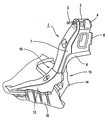
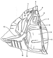
- the wheel arch inner wall 9 is welded in the region of the triple weld 15 both with the flanges 8 of the backrest holder 1 and with the damper holder 14.
- the reinforcement angle 12 in the region of the connecting surface 11 is welded to the rear holder 1 and on its opposite side to the bottom plate 10.
Landscapes
- Engineering & Computer Science (AREA)
- Transportation (AREA)
- Mechanical Engineering (AREA)
- Aviation & Aerospace Engineering (AREA)
- Chemical & Material Sciences (AREA)
- Combustion & Propulsion (AREA)
- Body Structure For Vehicles (AREA)
- Seats For Vehicles (AREA)
Claims (9)
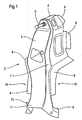
- Dispositif comprenant un support de dossier arrière (1) d'un véhicule à moteur avec un boulon (3) ou un étrier qui se met en prise, quand l'arrière du dossier arrière est redressé verticalement, dans un verrou de l'arrière du dossier et qui peut être fixé sur la paroi intérieure de la carrosserie (5) et la paroi intérieure du logement de roue (9) qui s'y raccorde, ainsi qu'une équerre de renfort (12) qui relie une tôle de plancher de carrosserie (10) à la paroi intérieure du logement de roue (9), le support de dossier arrière (1) étant conformé comme un élément de carrosserie pouvant être intégré du point de vue fonctionnel dans la structure de carrosserie ou de châssis du véhicule à moteur absorbant les forces et raidissant la zone du logement de roue arrière, qui se compose d'un élément de base s'étendant, dans sa position de fixation, de la paroi intérieure de la carrosserie (5) au moins jusqu'à proximité de la tôle de plancher de carrosserie (10) et repose au moins en partie sur le contour de paroi du logement de roue situé du côté intérieur de la carrosserie, et le support de dossier arrière (1) présente en outre des brides et/ou des zones (8, 15) pour interagir avec une fixation (14) pour un amortisseur fixée à proximité du boulon (3) ou de l'étrier sur le logement de roue, des surfaces de butée et/ou de liaison (11) étant en outre formées pour l'interaction avec l'équerre de renfort (12) reliant la tôle de plancher (10) à la paroi intérieure du logement de roue (9) et le support de dossier arrière (1) étant combiné dans sa partie inférieure avec une équerre de renfort (12) reliant la tôle de plancher (10) à la paroi intérieure du logement de roue (9) et pouvant être intégré du point de vue fonctionnel dans la structure de carrosserie absorbant les forces, des brides de soudage formant des surfaces de liaison étant formées sur le côté de l'élément de base faisant face au boulon (3), avec lesquelles le support de dossier arrière (1) est soudé à la paroi intérieure de la carrosserie (5) et le support de dossier arrière (1) étant muni d'autres brides de soudage (6) qui sont disposées en dessous des brides (4) et qui sont également soudées à la paroi intérieure de la carrosserie (5) dans la position de fixation du support de dossier arrière (1).
- Disposition selon la revendication 1, caractérisée en ce que le support de dossier arrière (1) peut, dans sa position de fixation, être amené à une position superposée à la paroi intérieure du logement de roue (9) et à la fixation (14) pour un amortisseur de telle manière qu'il puisse être intégré à demeure dans la structure de carrosserie absorbant la force dans sa partie inférieure au moyen d'une triple soudure du support de dossier arrière (1), de la paroi intérieure du logement de roue (9) et de la fixation (14) pour un amortisseur à la paroi intérieure du logement de roue (9) et à la fixation d'amortisseur (14).
- Disposition selon l'une des revendications précédentes, caractérisée en ce que le support de dossier arrière (1) et/ou l'équerre de renfort (12) et/ou la fixation d'amortisseur (14) sont conformés comme des profilés en caisson ou des profilés en U.
- Disposition selon l'une des revendications précédentes, caractérisée en ce que le support de dossier arrière (1) est soudé la paroi intérieure latérale de la carrosserie (5) et/ou à la paroi intérieure du logement de roue (9) et/ou à l'équerre de renfort (12) et/ou à la fixation (14) pour l'amortisseur et forme ainsi une structure de carrosserie absorbant les forces.
- Véhicule à moteur avec une disposition selon l'une des revendications 1 à 4.
- Véhicule à moteur selon la revendication 5, caractérisé en ce que le support de dossier (1) présente des brides de soudage (4, 6, 8, 13) qui reposent sur la paroi intérieure du logement de roue (9) et/ou la paroi intérieure latérale de la carrosserie (5) et sont soudées à celles-ci.
- Véhicule à moteur selon l'une des revendications 5 ou 6, caractérisé en ce que le support de dossier arrière (1) est soudé à demeure dans sa partie inférieure (15) au moyen d'une triple soudure du support de dossier arrière (1), de la paroi intérieure du logement de roue (9) et de la fixation (14) pour un amortisseur à la paroi intérieure du logement de roue (9) et à la fixation d'amortisseur (14) et intégré dans la structure de carrosserie absorbant les forces.
- Véhicule à moteur selon l'une des revendications 5 à 7, caractérisé en ce que le support de dossier arrière (1) est soudé dans sa partie inférieure (11) à une équerre de renfort (12) reliant la tôle de plancher (10) et la paroi intérieure du logement de roue (9).
- Véhicule à moteur selon l'une des revendications 5 à 8, caractérisé en ce que le support de dossier arrière (1) et/ou l'équerre de renfort (12) et/ou la fixation d'amortisseur (14) sont conformés comme des profilés en caisson ou des profilés en U.
Applications Claiming Priority (2)
| Application Number | Priority Date | Filing Date | Title |
|---|---|---|---|
| DE10235112 | 2002-08-01 | ||
| DE2002135112 DE10235112A1 (de) | 2002-08-01 | 2002-08-01 | Bodyintegrierter Sitzhalter |
Publications (2)
| Publication Number | Publication Date |
|---|---|
| EP1386830A1 EP1386830A1 (fr) | 2004-02-04 |
| EP1386830B1 true EP1386830B1 (fr) | 2016-02-24 |
Family
ID=30010548
Family Applications (1)
| Application Number | Title | Priority Date | Filing Date |
|---|---|---|---|
| EP03016483.4A Expired - Lifetime EP1386830B1 (fr) | 2002-08-01 | 2003-07-22 | Support de banquette intégré dans la structure de véhicule |
Country Status (2)
| Country | Link |
|---|---|
| EP (1) | EP1386830B1 (fr) |
| DE (1) | DE10235112A1 (fr) |
Families Citing this family (2)
| Publication number | Priority date | Publication date | Assignee | Title |
|---|---|---|---|---|
| DE102004014668B4 (de) * | 2004-03-25 | 2008-10-30 | Audi Ag | Verstrebung für einen Laderaumboden |
| FR3078520B1 (fr) | 2018-03-05 | 2020-02-14 | Psa Automobiles Sa | Panneau en tole constituant une doublure de la partie arriere d’un cote de caisse d’un vehicule et un passage de roue arriere |
Citations (2)
| Publication number | Priority date | Publication date | Assignee | Title |
|---|---|---|---|---|
| US5350214A (en) * | 1992-05-08 | 1994-09-27 | Mazda Motor Corporation | Rear body structure for automotive vehicle |
| US5997068A (en) * | 1997-04-01 | 1999-12-07 | Suzuki Motor Corporation | Seat back attaching construction for a vehicular seat |
Family Cites Families (4)
| Publication number | Priority date | Publication date | Assignee | Title |
|---|---|---|---|---|
| DE19620877C1 (de) * | 1996-05-23 | 1997-06-26 | Bayerische Motoren Werke Ag | Sitzanordnung in einem Kraftfahrzeug |
| KR100296270B1 (ko) * | 1999-06-21 | 2001-07-12 | 이계안 | 자동차의 리어휠하우징 보강구조 |
| DE10109784B4 (de) * | 2001-02-28 | 2006-09-28 | Daimlerchrysler Ag | Selbsttragende Karosserie für einen Personenkraftwagen |
| DE10162022A1 (de) * | 2001-12-18 | 2003-07-03 | Opel Adam Ag | Einrichtung zum lösbaren Befestigen der Rückenlehne einer Rückbank |
-
2002
- 2002-08-01 DE DE2002135112 patent/DE10235112A1/de not_active Withdrawn
-
2003
- 2003-07-22 EP EP03016483.4A patent/EP1386830B1/fr not_active Expired - Lifetime
Patent Citations (2)
| Publication number | Priority date | Publication date | Assignee | Title |
|---|---|---|---|---|
| US5350214A (en) * | 1992-05-08 | 1994-09-27 | Mazda Motor Corporation | Rear body structure for automotive vehicle |
| US5997068A (en) * | 1997-04-01 | 1999-12-07 | Suzuki Motor Corporation | Seat back attaching construction for a vehicular seat |
Also Published As
| Publication number | Publication date |
|---|---|
| EP1386830A1 (fr) | 2004-02-04 |
| DE10235112A1 (de) | 2004-02-19 |
Similar Documents
| Publication | Publication Date | Title |
|---|---|---|
| DE10219764B4 (de) | Klappbare Fahrzeugbordwand mit daran befestigten Sitzkomponenten | |
| DE3617961C2 (fr) | ||
| AT404459B (de) | Ladeboden für den laderaum eines fahrzeuges | |
| DE102009012057B4 (de) | Vorrichtung zum Aufnehmen von Seitenkräften und Kraftfahrzeug mit einer derartigen Vorrichtung | |
| EP1123224A1 (fr) | Recouvrement destine a l'espace de chargement d'un vehicule automobile | |
| DE102011010717A1 (de) | Äußere Seitenwandstruktur, äußeres Seitenwandmodul und Seitenwand für ein Kraftfahrzeug | |
| DE102015007453A1 (de) | Kraftfahrzeugkarosserie | |
| DE102012006527A1 (de) | Bodenstruktur einer Kraftfahrzeugkarosserie | |
| DE10261393B4 (de) | Höhenverstellbares Laderaumbodensystem | |
| DE4202103C2 (de) | Personenkraftwagen mit einer als Wickelsitz ausgeführten Rücksitzanordnung | |
| DE102011121906A1 (de) | Bodenstruktur einer Kraftfahrzeugkarosserie | |
| WO2005012068A1 (fr) | Cabine de conducteur pour un vehicule utilitaire | |
| DE10109784B4 (de) | Selbsttragende Karosserie für einen Personenkraftwagen | |
| EP3275739B1 (fr) | Vehicule avec un support comprenant au moins un dispositif de montage de ceinture de sécurité | |
| EP1386830B1 (fr) | Support de banquette intégré dans la structure de véhicule | |
| DE102021108428A1 (de) | Baugruppe und montageverfahren für eine fahrzeugstützstruktur | |
| DE19829832B4 (de) | Karosseriestruktur für ein Kraftfahrzeug | |
| DE102008027552A1 (de) | Kraftfahrzeug mit Querstrebe im hinteren Ladebereich | |
| DE602004002456T2 (de) | Vordere fussanordnung in einem pkw | |
| WO2005056370A1 (fr) | Structure de cadre porteur comprenant un element de carrosserie en acier moule a paroi mince | |
| EP0825094A1 (fr) | Carrosserie avant pour un véhicule à moteur | |
| DE102009039807A1 (de) | Frontstruktur eines Kraftfahrzeugs | |
| DE602004002196T2 (de) | Vordere fussanordnung in einem pkw | |
| EP1258390A1 (fr) | Dossier pour véhicule automobile | |
| DE10026336B4 (de) | Rohbaukarosserie für einen Personenkraftwagen |
Legal Events
| Date | Code | Title | Description |
|---|---|---|---|
| PUAI | Public reference made under article 153(3) epc to a published international application that has entered the european phase |
Free format text: ORIGINAL CODE: 0009012 |
|
| AK | Designated contracting states |
Kind code of ref document: A1 Designated state(s): AT BE BG CH CY CZ DE DK EE ES FI FR GB GR HU IE IT LI LU MC NL PT RO SE SI SK TR |
|
| AX | Request for extension of the european patent |
Extension state: AL LT LV MK |
|
| 17P | Request for examination filed |
Effective date: 20040729 |
|
| AKX | Designation fees paid |
Designated state(s): DE ES FR GB |
|
| RAP1 | Party data changed (applicant data changed or rights of an application transferred) |
Owner name: GM GLOBAL TECHNOLOGY OPERATIONS, INC. |
|
| RAP1 | Party data changed (applicant data changed or rights of an application transferred) |
Owner name: GM GLOBAL TECHNOLOGY OPERATIONS LLC |
|
| GRAP | Despatch of communication of intention to grant a patent |
Free format text: ORIGINAL CODE: EPIDOSNIGR1 |
|
| INTG | Intention to grant announced |
Effective date: 20150929 |
|
| GRAS | Grant fee paid |
Free format text: ORIGINAL CODE: EPIDOSNIGR3 |
|
| GRAA | (expected) grant |
Free format text: ORIGINAL CODE: 0009210 |
|
| AK | Designated contracting states |
Kind code of ref document: B1 Designated state(s): DE ES FR GB |
|
| REG | Reference to a national code |
Ref country code: GB Ref legal event code: FG4D Free format text: NOT ENGLISH |
|
| REG | Reference to a national code |
Ref country code: DE Ref legal event code: R096 Ref document number: 50315410 Country of ref document: DE |
|
| REG | Reference to a national code |
Ref country code: FR Ref legal event code: PLFP Year of fee payment: 14 |
|
| PG25 | Lapsed in a contracting state [announced via postgrant information from national office to epo] |
Ref country code: ES Free format text: LAPSE BECAUSE OF FAILURE TO SUBMIT A TRANSLATION OF THE DESCRIPTION OR TO PAY THE FEE WITHIN THE PRESCRIBED TIME-LIMIT Effective date: 20160224 |
|
| PGFP | Annual fee paid to national office [announced via postgrant information from national office to epo] |
Ref country code: FR Payment date: 20160613 Year of fee payment: 14 |
|
| PGFP | Annual fee paid to national office [announced via postgrant information from national office to epo] |
Ref country code: GB Payment date: 20160720 Year of fee payment: 14 |
|
| REG | Reference to a national code |
Ref country code: DE Ref legal event code: R097 Ref document number: 50315410 Country of ref document: DE |
|
| PLBE | No opposition filed within time limit |
Free format text: ORIGINAL CODE: 0009261 |
|
| STAA | Information on the status of an ep patent application or granted ep patent |
Free format text: STATUS: NO OPPOSITION FILED WITHIN TIME LIMIT |
|
| 26N | No opposition filed |
Effective date: 20161125 |
|
| PGFP | Annual fee paid to national office [announced via postgrant information from national office to epo] |
Ref country code: DE Payment date: 20170719 Year of fee payment: 15 |
|
| GBPC | Gb: european patent ceased through non-payment of renewal fee |
Effective date: 20170722 |
|
| REG | Reference to a national code |
Ref country code: FR Ref legal event code: ST Effective date: 20180330 |
|
| PG25 | Lapsed in a contracting state [announced via postgrant information from national office to epo] |
Ref country code: GB Free format text: LAPSE BECAUSE OF NON-PAYMENT OF DUE FEES Effective date: 20170722 |
|
| PG25 | Lapsed in a contracting state [announced via postgrant information from national office to epo] |
Ref country code: FR Free format text: LAPSE BECAUSE OF NON-PAYMENT OF DUE FEES Effective date: 20170731 |
|
| REG | Reference to a national code |
Ref country code: DE Ref legal event code: R119 Ref document number: 50315410 Country of ref document: DE |
|
| PG25 | Lapsed in a contracting state [announced via postgrant information from national office to epo] |
Ref country code: DE Free format text: LAPSE BECAUSE OF NON-PAYMENT OF DUE FEES Effective date: 20190201 |