EP1387104A2 - Moyens d'équilibrage dans un embrayage à friction - Google Patents
Moyens d'équilibrage dans un embrayage à friction Download PDFInfo
- Publication number
- EP1387104A2 EP1387104A2 EP03016372A EP03016372A EP1387104A2 EP 1387104 A2 EP1387104 A2 EP 1387104A2 EP 03016372 A EP03016372 A EP 03016372A EP 03016372 A EP03016372 A EP 03016372A EP 1387104 A2 EP1387104 A2 EP 1387104A2
- Authority
- EP
- European Patent Office
- Prior art keywords
- mass element
- friction clutch
- plate spring
- spring
- clutch
- Prior art date
- Legal status (The legal status is an assumption and is not a legal conclusion. Google has not performed a legal analysis and makes no representation as to the accuracy of the status listed.)
- Granted
Links
- 238000002485 combustion reaction Methods 0.000 claims abstract description 3
- 230000005540 biological transmission Effects 0.000 claims 1
- 150000001875 compounds Chemical class 0.000 abstract 1
- 230000005484 gravity Effects 0.000 description 11
- 238000000034 method Methods 0.000 description 8
- 210000002105 tongue Anatomy 0.000 description 8
- 238000010168 coupling process Methods 0.000 description 7
- 230000008878 coupling Effects 0.000 description 5
- 238000005859 coupling reaction Methods 0.000 description 5
- 230000003321 amplification Effects 0.000 description 3
- 238000003199 nucleic acid amplification method Methods 0.000 description 3
- 238000009826 distribution Methods 0.000 description 2
- 238000004519 manufacturing process Methods 0.000 description 2
- 238000002844 melting Methods 0.000 description 2
- 230000008018 melting Effects 0.000 description 2
- 239000012528 membrane Substances 0.000 description 2
- 238000004080 punching Methods 0.000 description 2
- 238000003466 welding Methods 0.000 description 2
- 229910045601 alloy Inorganic materials 0.000 description 1
- 239000000956 alloy Substances 0.000 description 1
- 238000013459 approach Methods 0.000 description 1
- 239000011324 bead Substances 0.000 description 1
- 238000005452 bending Methods 0.000 description 1
- 230000009286 beneficial effect Effects 0.000 description 1
- 230000015572 biosynthetic process Effects 0.000 description 1
- 238000005266 casting Methods 0.000 description 1
- 238000006073 displacement reaction Methods 0.000 description 1
- 230000000694 effects Effects 0.000 description 1
- 238000004049 embossing Methods 0.000 description 1
- 238000010438 heat treatment Methods 0.000 description 1
- 229910001385 heavy metal Inorganic materials 0.000 description 1
- 238000009434 installation Methods 0.000 description 1
Images



Classifications
-
- F—MECHANICAL ENGINEERING; LIGHTING; HEATING; WEAPONS; BLASTING
- F16—ENGINEERING ELEMENTS AND UNITS; GENERAL MEASURES FOR PRODUCING AND MAINTAINING EFFECTIVE FUNCTIONING OF MACHINES OR INSTALLATIONS; THERMAL INSULATION IN GENERAL
- F16D—COUPLINGS FOR TRANSMITTING ROTATION; CLUTCHES; BRAKES
- F16D13/00—Friction clutches
- F16D13/58—Details
- F16D13/583—Diaphragm-springs, e.g. Belleville
Definitions
- the invention relates to a friction clutch, in particular for motor vehicles, comprising an attached to the flywheel of an internal combustion engine Coupling housing, a non-rotatable but axially displaceable with the coupling housing Pressure plate, one between the flywheel and the pressure plate rotatably clutch disc arranged on a gear shaft, a plate spring for loading the friction linings of the clutch disc over the pressure plate.
- Diaphragm spring clutches are known (DE 43 42 361 A1) with a Flywheel and an associated clutch housing, one with the Coupling housing via pressure plate connected by leaf springs and a diaphragm spring. Centrifugal weights can be moved here in areas of the diaphragm spring tongues recorded, which at reaching a predetermined centrifugal force come to an attack.
- the disadvantage here is that it is a A large number of components are involved, with a corresponding one in the radially inner region Space requirements must be kept.
- friction clutches are known (US 2,885,047; DE 24 50 267 C2), in which the diaphragm spring tongues for a shift in the center of gravity axially exhibited are. This results in an additional moment, which at Influencing centrifugal force increases the contact pressure in the engaged state, and an influence on the disengagement force during the disengagement process is present.
- Such solutions cannot be carried out in confined spaces because the adjacent components, such as. B. Releaser and clutch disc, limited space are and a noticeable increase in power the weight of the clutch desirably increased.
- the object is achieved in that in the outer edge region the plate spring is arranged at least one mass element.
- the clutch can be used together with the Flywheel while maintaining the rotational moment of inertia with less Weight can be designed as without mass element.
- the center of gravity of the mass element from the abutment the disc spring on the clutch housing axially in the direction of the clutch housing, So in the direction away from the friction linings, acts in those cases the contact area of the plate spring on the pressure plate radially outside of Abutment of the diaphragm spring is located on the clutch housing, one with the speed of the friction clutch increases the tilting moment on the disc spring, which acts to increase the contact pressure.
- a pressed clutch Such an arrangement of the plate spring in the friction clutch.
- connection of the mass element can be radial outside in the edge area or outside the edge area of the plate spring and then at least partially overlapping radially inwards with the plate spring extend.
- Another embodiment provides that the mass element over the entire Circumference is arranged.
- the mass element In addition to a primarily inexpensive Manufacturing and low component diversity is the angular position of the mass element irrelevant with regard to the housing, the diaphragm spring and the other components, which simplifies the assembly of a friction clutch.
- several mass elements are distributed over the circumference arranged. Especially when the axial distance from the support point on the clutch housing of the center of gravity of a mass element becomes a larger moment and at the contact area of the disc spring achieved a higher force gain at speed on the pressure plate.
- the mass element or elements can also be formed in one piece with the plate spring his. Are the mass element on the radially outer edge area of the plate spring formed as a flap-like training that bent in the axial direction are, these tabs in openings or openings in the Grip clutch housing in the axial direction.
- the weight can be further of a mass element increase if the tabs by bent, folded Edge areas are formed in multiple layers. Also the end areas the tabs be unwound in the radial direction. But it is also possible, alternatively for this or in addition the mass elements fixed but detachable with the To connect disc spring or attach additional masses. This can be done by Riveting, screwing or welding attached as a further mass element become.
- the mass elements can also compensate for unbalance be used.
- Additional weights can be used here, similar to balancing of car tires, using retaining clips on the disc spring or a mass element be attached. Especially when axially extending sections The additional weights can form as mass elements on the plate spring a different imbalance distribution by shifting in the axial direction balanced within the friction clutch in the axial direction.
- the clutch housing With an axial extension of the mass element in the direction of the clutch housing it is advantageously provided that the clutch housing corresponding Has recesses or bulges for this. These can be beneficial introduced by means of a punching or embossing process in the clutch housing become.
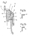
- the friction linings are 6 indicated a clutch disc in contact with a pressure plate 3, which via leaf springs, not shown here, non-rotatably, but axially movable with the clutch housing 2 is riveted.
- the pressure plate 3 is 5 by means of a plate spring towards a flywheel and the friction linings 6 for transferring a Torque applied.
- the plate spring 5 is the first one Abutment 9a, which here has the design of a circumferential wire ring, and a second abutment 9b, which here as well as a rotating one Wire ring is formed on the clutch housing 2 around this bearing pivoted.
- the plate spring is supported here 5 on the second abutment 9b and the circumferentially formed on the pressure plate 3 Support point 10 from.
- this has a ring-like circumferential, with a plurality of one another in the circumferential direction following arranged projections 12 provided mass element 4.
- This Mass element 4 is composed of one on the outer edge of the plate spring 5 pressed ring, which angled extensions 12 evenly over distributed the scope. These extensions 12 penetrate in the axial direction corresponding cutouts 13 introduced into the clutch housing 2, which are in turn designed in such a way that the mass element 4 with its axial extensions 12 with a swiveling movement of the plate spring 5 during an on and In this regard, the disengaging process has sufficient clearance to prevent a collision to avoid.
- the connection between the mass element 4 and the plate spring 5 be carried out by means of a laser welding process. Here it is in Generally sufficient if several individual, interrupted ones are distributed over the circumference Welds of limited length ensure the connection of the components.
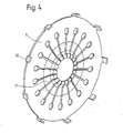
- FIG. 3 shows a top view of the friction clutch 8 shown in FIG. 1 with the radially inner membrane spring tongues 11, which as Serve the lever of the plate spring 5. Furthermore, the outbreaks 13, through which the extensions 12 of the mass element 4 extend, can be seen.
- a diaphragm spring is shown, which for use in an inventive 1 is provided.
- the embodiment of FIG. 1 is then on the radially outside lying end region of the plate spring 5 with the configuration according to the invention the extensions 12 made in one piece.
- the plate spring 5 goes radially inwards the diaphragm spring tongues 11, by means of which the plate spring 5 during a Coupling process is actuated.
- the extensions 12 by means of a punching process and subsequent forming process before hardening the disc spring.
- the number and distribution of the extensions 12 can vary as desired become.
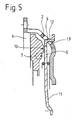
- the friction clutch 8 shown in FIG. 5 differs from that in FIG Fig. 1 embodiment shown by a different geometric configuration of the mass element 4.
- the extension 12 sits in the axial direction through the cutout 13 and then has one predominantly radially extending continuation. This allows the center of gravity of the mass element 4 in the axial direction further from the system of Disc spring 5 is located at support point 10.
- Outbreak 13 is ideal here shaped such that the mass element 4 both during the pivoting movement the plate spring 5 during a coupling process and as a result of Wear of the friction linings 6 causes the diaphragm spring 5 to tilt with an accompanying axial displacement of the pressure plate 3 in the direction of the flywheel the freedom of movement between mass element 4 and the outbreak 13 is guaranteed.
- the area of the mass element 4, which is outside the engagement area with the cutout 13 can be in the circumferential direction a greater extent than that area of the mass element 4 which through the cutout 13 in the assembled state in the circumferential direction is covered. So z. B. in the embodiment shown in Fig. 3 the extension 12 of the mass element 4 a greater distance in the circumferential direction from the wall of the outbreak 13 as this purely during the Assembly would be necessary.
- the diaphragm spring the friction clutch 8 configured such that in the circumferential direction on the radial 5 outer fastening area 14 are formed.
- These fastening regions 14 have an extent similar in the circumferential direction the extensions 12 corresponding to FIG. 4, and are in the in Fig. 6 and 7th shown examples mainly aligned radially.
- this inclined to the plane of the plate spring 5 to design.
- To these attachment areas 14 are separate individual mass elements by means of fastening means 15 4 attached. These mass elements 4 can have a corresponding configuration 1 and 5, by the separate manufacture of the plate spring 5 and the mass elements 4 result in cost advantages for small quantities.
- the mass element 4 is on the Attachment area 14 riveted, but it is also possible to screw them or to stick.
- the mass element 4 shown in FIG. 7 has an as Rivet-shaped fastening means 15 in one piece with the mass element 4.
- the mass element 4 can also be attached to the fastening area 14 a casting process attached and manufactured itself. Suitable for this alloys with a correspondingly low melting point and a high specific weight (lead or other heavy metals), whereby whose melting point is a subsequent heat treatment of the plate spring 5 not limited.
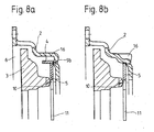
- the friction clutch shown in FIGS. 8a and 8b differs from that previously shown embodiments in that here a drawn friction clutch is shown.
- a drawn friction clutch is shown.
- the fastening of the plate spring 5 on the housing which is explained in FIG. 1 2 about a first abutment 9a and a second abutment 9b is not here required because both in the disengaged and in the engaged state the plate spring 5 is at the support point corresponding to the second abutment 9b supported on the clutch housing 2.
- the plate spring 5 is actuated analogously via membrane spring tongues attached to it 11.
- the diaphragm spring tongues 11 are not in the direction of the friction linings 6 but moved axially away from them. Because friction clutches pulled are used in particular when particularly strong disc springs 5 used, the clutch housing 2 must be designed to be particularly rigid his. 8a, the plate spring 5 is in one Area cut by the radially outer edge area, similar to the embodiment 4, a mass element pointing primarily in the axial direction followed.
- the Coupling housing 2 also has to cooperate with the several, in Arranged circumferential mass elements 4 bulges 16 which, for. B. can be impressed as enlarged beads. These bulges 16 are corresponding to the mass elements 4 in the circumferential direction in the clutch housing 2 trained.
Landscapes
- Engineering & Computer Science (AREA)
- General Engineering & Computer Science (AREA)
- Mechanical Engineering (AREA)
- Mechanical Operated Clutches (AREA)
Applications Claiming Priority (2)
| Application Number | Priority Date | Filing Date | Title |
|---|---|---|---|
| DE10235709 | 2002-08-03 | ||
| DE10235709A DE10235709A1 (de) | 2002-08-03 | 2002-08-03 | Reibungskupplung |
Publications (3)
| Publication Number | Publication Date |
|---|---|
| EP1387104A2 true EP1387104A2 (fr) | 2004-02-04 |
| EP1387104A3 EP1387104A3 (fr) | 2004-08-18 |
| EP1387104B1 EP1387104B1 (fr) | 2007-10-31 |
Family
ID=30010599
Family Applications (1)
| Application Number | Title | Priority Date | Filing Date |
|---|---|---|---|
| EP03016372A Expired - Lifetime EP1387104B1 (fr) | 2002-08-03 | 2003-07-19 | Moyens d'équilibrage dans un embrayage à friction |
Country Status (3)
| Country | Link |
|---|---|
| EP (1) | EP1387104B1 (fr) |
| AT (1) | ATE377161T1 (fr) |
| DE (2) | DE10235709A1 (fr) |
Cited By (3)
| Publication number | Priority date | Publication date | Assignee | Title |
|---|---|---|---|---|
| FR2853374A1 (fr) * | 2003-04-05 | 2004-10-08 | Zf Sachs Ag | Groupe de plateaux de pression pour un embrayage a friction |
| DE102013203853A1 (de) | 2013-03-07 | 2014-09-11 | Schaeffler Technologies Gmbh & Co. Kg | Kupplung für einen Antriebsstrang eines Kraftfahrzeugs mit verlagerbaren Massen |
| DE102014218398A1 (de) | 2013-10-21 | 2015-04-23 | Schaeffler Technologies Gmbh & Co. Kg | Tellerfeder mit Fliehkraftzungen |
Families Citing this family (1)
| Publication number | Priority date | Publication date | Assignee | Title |
|---|---|---|---|---|
| DE102014211309A1 (de) * | 2014-06-13 | 2015-12-17 | Schaeffler Technologies AG & Co. KG | Druckplattenbaugruppe mit Hebelelement zur Vergrößerung des Abhubs und Kupplungsvorrichtung mit Druckplattenbaugruppe |
Citations (3)
| Publication number | Priority date | Publication date | Assignee | Title |
|---|---|---|---|---|
| US2885047A (en) | 1957-07-18 | 1959-05-05 | Gen Motors Corp | Clutch assembly |
| DE2450267C2 (fr) | 1974-10-23 | 1989-11-09 | Luk Lamellen Und Kupplungsbau Gmbh, 7580 Buehl, De | |
| DE4342361A1 (de) | 1993-12-11 | 1995-06-14 | Fichtel & Sachs Ag | Membranfederkupplung mit Fliehgewichten |
Family Cites Families (5)
| Publication number | Priority date | Publication date | Assignee | Title |
|---|---|---|---|---|
| DE1099280B (de) * | 1957-07-18 | 1961-02-09 | Gen Motors Corp | Reibungskupplung |
| US4425991A (en) * | 1981-05-18 | 1984-01-17 | Hays Bill J | Automotive clutch improvements |
| US4520912A (en) * | 1982-10-18 | 1985-06-04 | Borg-Warner Corporation | Hydraulically actuated starting clutch assembly |
| JPS59131033A (ja) * | 1983-01-12 | 1984-07-27 | H K S:Kk | ダイヤフラムスプリング式クラツチ装置 |
| FR2812918B1 (fr) * | 2000-08-11 | 2003-03-07 | Valeo | Perfectionnement a un mecanisme d'embrayage a diaphragme pour moteur de vehicule automobile |
-
2002
- 2002-08-03 DE DE10235709A patent/DE10235709A1/de not_active Withdrawn
-
2003
- 2003-07-19 AT AT03016372T patent/ATE377161T1/de not_active IP Right Cessation
- 2003-07-19 DE DE50308483T patent/DE50308483D1/de not_active Expired - Lifetime
- 2003-07-19 EP EP03016372A patent/EP1387104B1/fr not_active Expired - Lifetime
Patent Citations (3)
| Publication number | Priority date | Publication date | Assignee | Title |
|---|---|---|---|---|
| US2885047A (en) | 1957-07-18 | 1959-05-05 | Gen Motors Corp | Clutch assembly |
| DE2450267C2 (fr) | 1974-10-23 | 1989-11-09 | Luk Lamellen Und Kupplungsbau Gmbh, 7580 Buehl, De | |
| DE4342361A1 (de) | 1993-12-11 | 1995-06-14 | Fichtel & Sachs Ag | Membranfederkupplung mit Fliehgewichten |
Cited By (4)
| Publication number | Priority date | Publication date | Assignee | Title |
|---|---|---|---|---|
| FR2853374A1 (fr) * | 2003-04-05 | 2004-10-08 | Zf Sachs Ag | Groupe de plateaux de pression pour un embrayage a friction |
| DE102013203853A1 (de) | 2013-03-07 | 2014-09-11 | Schaeffler Technologies Gmbh & Co. Kg | Kupplung für einen Antriebsstrang eines Kraftfahrzeugs mit verlagerbaren Massen |
| DE102014218398A1 (de) | 2013-10-21 | 2015-04-23 | Schaeffler Technologies Gmbh & Co. Kg | Tellerfeder mit Fliehkraftzungen |
| DE102014218398B4 (de) * | 2013-10-21 | 2020-10-15 | Schaeffler Technologies AG & Co. KG | Tellerfeder mit Fliehkraftzungen |
Also Published As
| Publication number | Publication date |
|---|---|
| EP1387104B1 (fr) | 2007-10-31 |
| EP1387104A3 (fr) | 2004-08-18 |
| DE50308483D1 (de) | 2007-12-13 |
| ATE377161T1 (de) | 2007-11-15 |
| DE10235709A1 (de) | 2004-02-19 |
Similar Documents
| Publication | Publication Date | Title |
|---|---|---|
| EP2494225B1 (fr) | Module d'embrayage | |
| EP3365579B1 (fr) | Amortisseur de vibrations de torsion et groupe propulseur hybride | |
| DE69700708T2 (de) | Biegsame Platte und Schwungradgestaltung | |
| DE102011017380A1 (de) | Doppelkupplung | |
| EP1693588B1 (fr) | Arrangement pour le support axial de deux éléments rotatifs. | |
| EP3123043B1 (fr) | Double embrayage à disques multiples | |
| EP4150227A1 (fr) | Ensemble d'embrayage multidisques ayant des unités de plaque de ressort à action indépendante pour relier deux disques de composant à un arbre de sortie | |
| EP3728889B1 (fr) | Unité de transmission de couple et chaîne cinématique | |
| EP1862685A1 (fr) | Agencement de transmission d'un couple de rotation pour le conducteur de commande d'un véhicule | |
| EP1387104B1 (fr) | Moyens d'équilibrage dans un embrayage à friction | |
| EP3440381B1 (fr) | System d'embrayage avec un dispositif d'amortissement des vibrations de torsion destiné à la chaîne cinématique d'un véhicule | |
| DE102017130853B4 (de) | Kupplungseinrichtung | |
| DE102004039905A1 (de) | Schwingungsdämpfungssystem | |
| EP3724534B1 (fr) | Pendule centrifuge et ensemble d'entraînement pour un véhicule automobile | |
| WO2021073683A1 (fr) | Amortisseur de vibrations de torsion | |
| DE102010042639B4 (de) | Kupplungsmechanismus mit Ausgleichsgewicht | |
| DE102015203718A1 (de) | Zwischenplatte für eine Mehrscheibenkupplung | |
| EP1647729A2 (fr) | Dispositif d'embrayages pour embrayages multiples | |
| DE102012211706A1 (de) | Reibungskupplung | |
| DE102013110080A1 (de) | Drehmomentübertragungseinheit mit einer Doppel-Trockenkupplung und einem Dämpfungsschwungrad | |
| EP1719930B1 (fr) | Ensemble de disque d'embrayage pour embrayages multiples, en particulier embrayage à deux disques | |
| EP1726843B1 (fr) | Ensemble embrayage | |
| DE102015207276A1 (de) | Reibkupplung mit einer Rotationsachse zum lösbaren Verbinden einer Abtriebswelle mit einem Verbraucher | |
| DE102019109981A1 (de) | Kupplungseinrichtung mit einer ein Spannelement aufweisenden Befestigungseinheit zwischen einem Drehschwingungsdämpfer und einer Trennkupplung | |
| EP1653103A2 (fr) | Dispositif d'embrayages pour embrayages multiples |
Legal Events
| Date | Code | Title | Description |
|---|---|---|---|
| PUAI | Public reference made under article 153(3) epc to a published international application that has entered the european phase |
Free format text: ORIGINAL CODE: 0009012 |
|
| AK | Designated contracting states |
Kind code of ref document: A2 Designated state(s): AT BE BG CH CY CZ DE DK EE ES FI FR GB GR HU IE IT LI LU MC NL PT RO SE SI SK TR |
|
| AX | Request for extension of the european patent |
Extension state: AL LT LV MK |
|
| PUAL | Search report despatched |
Free format text: ORIGINAL CODE: 0009013 |
|
| AK | Designated contracting states |
Kind code of ref document: A3 Designated state(s): AT BE BG CH CY CZ DE DK EE ES FI FR GB GR HU IE IT LI LU MC NL PT RO SE SI SK TR |
|
| AX | Request for extension of the european patent |
Extension state: AL LT LV MK |
|
| 17P | Request for examination filed |
Effective date: 20040807 |
|
| 17Q | First examination report despatched |
Effective date: 20041207 |
|
| AKX | Designation fees paid |
Designated state(s): AT BE BG CH CY CZ DE DK EE ES FI FR GB GR HU IE IT LI LU MC NL PT RO SE SI SK TR |
|
| GRAP | Despatch of communication of intention to grant a patent |
Free format text: ORIGINAL CODE: EPIDOSNIGR1 |
|
| GRAS | Grant fee paid |
Free format text: ORIGINAL CODE: EPIDOSNIGR3 |
|
| GRAA | (expected) grant |
Free format text: ORIGINAL CODE: 0009210 |
|
| AK | Designated contracting states |
Kind code of ref document: B1 Designated state(s): AT BE BG CH CY CZ DE DK EE ES FI FR GB GR HU IE IT LI LU MC NL PT RO SE SI SK TR |
|
| REG | Reference to a national code |
Ref country code: GB Ref legal event code: FG4D Free format text: NOT ENGLISH |
|
| REG | Reference to a national code |
Ref country code: IE Ref legal event code: FG4D Free format text: LANGUAGE OF EP DOCUMENT: GERMAN |
|
| REG | Reference to a national code |
Ref country code: CH Ref legal event code: EP |
|
| REF | Corresponds to: |
Ref document number: 50308483 Country of ref document: DE Date of ref document: 20071213 Kind code of ref document: P |
|
| NLV1 | Nl: lapsed or annulled due to failure to fulfill the requirements of art. 29p and 29m of the patents act | ||
| PG25 | Lapsed in a contracting state [announced via postgrant information from national office to epo] |
Ref country code: SE Free format text: LAPSE BECAUSE OF FAILURE TO SUBMIT A TRANSLATION OF THE DESCRIPTION OR TO PAY THE FEE WITHIN THE PRESCRIBED TIME-LIMIT Effective date: 20080131 Ref country code: ES Free format text: LAPSE BECAUSE OF FAILURE TO SUBMIT A TRANSLATION OF THE DESCRIPTION OR TO PAY THE FEE WITHIN THE PRESCRIBED TIME-LIMIT Effective date: 20080211 Ref country code: NL Free format text: LAPSE BECAUSE OF FAILURE TO SUBMIT A TRANSLATION OF THE DESCRIPTION OR TO PAY THE FEE WITHIN THE PRESCRIBED TIME-LIMIT Effective date: 20071031 |
|
| ET | Fr: translation filed | ||
| GBV | Gb: ep patent (uk) treated as always having been void in accordance with gb section 77(7)/1977 [no translation filed] | ||
| PG25 | Lapsed in a contracting state [announced via postgrant information from national office to epo] |
Ref country code: BG Free format text: LAPSE BECAUSE OF FAILURE TO SUBMIT A TRANSLATION OF THE DESCRIPTION OR TO PAY THE FEE WITHIN THE PRESCRIBED TIME-LIMIT Effective date: 20080131 Ref country code: SI Free format text: LAPSE BECAUSE OF FAILURE TO SUBMIT A TRANSLATION OF THE DESCRIPTION OR TO PAY THE FEE WITHIN THE PRESCRIBED TIME-LIMIT Effective date: 20071031 Ref country code: PT Free format text: LAPSE BECAUSE OF FAILURE TO SUBMIT A TRANSLATION OF THE DESCRIPTION OR TO PAY THE FEE WITHIN THE PRESCRIBED TIME-LIMIT Effective date: 20080331 |
|
| REG | Reference to a national code |
Ref country code: IE Ref legal event code: FD4D |
|
| PG25 | Lapsed in a contracting state [announced via postgrant information from national office to epo] |
Ref country code: DK Free format text: LAPSE BECAUSE OF FAILURE TO SUBMIT A TRANSLATION OF THE DESCRIPTION OR TO PAY THE FEE WITHIN THE PRESCRIBED TIME-LIMIT Effective date: 20071031 Ref country code: CZ Free format text: LAPSE BECAUSE OF FAILURE TO SUBMIT A TRANSLATION OF THE DESCRIPTION OR TO PAY THE FEE WITHIN THE PRESCRIBED TIME-LIMIT Effective date: 20071031 |
|
| PG25 | Lapsed in a contracting state [announced via postgrant information from national office to epo] |
Ref country code: SK Free format text: LAPSE BECAUSE OF FAILURE TO SUBMIT A TRANSLATION OF THE DESCRIPTION OR TO PAY THE FEE WITHIN THE PRESCRIBED TIME-LIMIT Effective date: 20071031 Ref country code: RO Free format text: LAPSE BECAUSE OF FAILURE TO SUBMIT A TRANSLATION OF THE DESCRIPTION OR TO PAY THE FEE WITHIN THE PRESCRIBED TIME-LIMIT Effective date: 20071031 |
|
| PLBE | No opposition filed within time limit |
Free format text: ORIGINAL CODE: 0009261 |
|
| STAA | Information on the status of an ep patent application or granted ep patent |
Free format text: STATUS: NO OPPOSITION FILED WITHIN TIME LIMIT |
|
| 26N | No opposition filed |
Effective date: 20080801 |
|
| PG25 | Lapsed in a contracting state [announced via postgrant information from national office to epo] |
Ref country code: IE Free format text: LAPSE BECAUSE OF FAILURE TO SUBMIT A TRANSLATION OF THE DESCRIPTION OR TO PAY THE FEE WITHIN THE PRESCRIBED TIME-LIMIT Effective date: 20071031 |
|
| PG25 | Lapsed in a contracting state [announced via postgrant information from national office to epo] |
Ref country code: GB Free format text: LAPSE BECAUSE OF FAILURE TO SUBMIT A TRANSLATION OF THE DESCRIPTION OR TO PAY THE FEE WITHIN THE PRESCRIBED TIME-LIMIT Effective date: 20071031 |
|
| PG25 | Lapsed in a contracting state [announced via postgrant information from national office to epo] |
Ref country code: GR Free format text: LAPSE BECAUSE OF FAILURE TO SUBMIT A TRANSLATION OF THE DESCRIPTION OR TO PAY THE FEE WITHIN THE PRESCRIBED TIME-LIMIT Effective date: 20080201 |
|
| PG25 | Lapsed in a contracting state [announced via postgrant information from national office to epo] |
Ref country code: FI Free format text: LAPSE BECAUSE OF FAILURE TO SUBMIT A TRANSLATION OF THE DESCRIPTION OR TO PAY THE FEE WITHIN THE PRESCRIBED TIME-LIMIT Effective date: 20071031 |
|
| REG | Reference to a national code |
Ref country code: CH Ref legal event code: PL |
|
| PG25 | Lapsed in a contracting state [announced via postgrant information from national office to epo] |
Ref country code: MC Free format text: LAPSE BECAUSE OF NON-PAYMENT OF DUE FEES Effective date: 20080731 |
|
| PG25 | Lapsed in a contracting state [announced via postgrant information from national office to epo] |
Ref country code: EE Free format text: LAPSE BECAUSE OF FAILURE TO SUBMIT A TRANSLATION OF THE DESCRIPTION OR TO PAY THE FEE WITHIN THE PRESCRIBED TIME-LIMIT Effective date: 20071031 |
|
| PG25 | Lapsed in a contracting state [announced via postgrant information from national office to epo] |
Ref country code: LI Free format text: LAPSE BECAUSE OF NON-PAYMENT OF DUE FEES Effective date: 20080731 Ref country code: CH Free format text: LAPSE BECAUSE OF NON-PAYMENT OF DUE FEES Effective date: 20080731 |
|
| PG25 | Lapsed in a contracting state [announced via postgrant information from national office to epo] |
Ref country code: CY Free format text: LAPSE BECAUSE OF FAILURE TO SUBMIT A TRANSLATION OF THE DESCRIPTION OR TO PAY THE FEE WITHIN THE PRESCRIBED TIME-LIMIT Effective date: 20071031 |
|
| PG25 | Lapsed in a contracting state [announced via postgrant information from national office to epo] |
Ref country code: AT Free format text: LAPSE BECAUSE OF NON-PAYMENT OF DUE FEES Effective date: 20080719 |
|
| PG25 | Lapsed in a contracting state [announced via postgrant information from national office to epo] |
Ref country code: LU Free format text: LAPSE BECAUSE OF NON-PAYMENT OF DUE FEES Effective date: 20080719 Ref country code: HU Free format text: LAPSE BECAUSE OF FAILURE TO SUBMIT A TRANSLATION OF THE DESCRIPTION OR TO PAY THE FEE WITHIN THE PRESCRIBED TIME-LIMIT Effective date: 20080501 Ref country code: BE Free format text: LAPSE BECAUSE OF NON-PAYMENT OF DUE FEES Effective date: 20080731 |
|
| PG25 | Lapsed in a contracting state [announced via postgrant information from national office to epo] |
Ref country code: TR Free format text: LAPSE BECAUSE OF FAILURE TO SUBMIT A TRANSLATION OF THE DESCRIPTION OR TO PAY THE FEE WITHIN THE PRESCRIBED TIME-LIMIT Effective date: 20071031 |
|
| PG25 | Lapsed in a contracting state [announced via postgrant information from national office to epo] |
Ref country code: IT Free format text: LAPSE BECAUSE OF NON-PAYMENT OF DUE FEES Effective date: 20080731 |
|
| PGFP | Annual fee paid to national office [announced via postgrant information from national office to epo] |
Ref country code: FR Payment date: 20110727 Year of fee payment: 9 |
|
| PGFP | Annual fee paid to national office [announced via postgrant information from national office to epo] |
Ref country code: DE Payment date: 20120711 Year of fee payment: 10 |
|
| REG | Reference to a national code |
Ref country code: FR Ref legal event code: ST Effective date: 20130329 |
|
| PG25 | Lapsed in a contracting state [announced via postgrant information from national office to epo] |
Ref country code: FR Free format text: LAPSE BECAUSE OF NON-PAYMENT OF DUE FEES Effective date: 20120731 |
|
| REG | Reference to a national code |
Ref country code: DE Ref legal event code: R081 Ref document number: 50308483 Country of ref document: DE Owner name: ZF FRIEDRICHSHAFEN AG, DE Free format text: FORMER OWNER: ZF SACHS AG, 97424 SCHWEINFURT, DE Effective date: 20130326 |
|
| PG25 | Lapsed in a contracting state [announced via postgrant information from national office to epo] |
Ref country code: DE Free format text: LAPSE BECAUSE OF NON-PAYMENT OF DUE FEES Effective date: 20140201 |
|
| REG | Reference to a national code |
Ref country code: DE Ref legal event code: R119 Ref document number: 50308483 Country of ref document: DE Effective date: 20140201 |