EP1387206A2 - Système optique à combinaison de couleurs, système d'affichage optique de type projection, affichage optique de type projection et système d'affichage optique - Google Patents
Système optique à combinaison de couleurs, système d'affichage optique de type projection, affichage optique de type projection et système d'affichage optique Download PDFInfo
- Publication number
- EP1387206A2 EP1387206A2 EP03254735A EP03254735A EP1387206A2 EP 1387206 A2 EP1387206 A2 EP 1387206A2 EP 03254735 A EP03254735 A EP 03254735A EP 03254735 A EP03254735 A EP 03254735A EP 1387206 A2 EP1387206 A2 EP 1387206A2
- Authority
- EP
- European Patent Office
- Prior art keywords
- light
- color
- optical system
- optical element
- optical
- Prior art date
- Legal status (The legal status is an assumption and is not a legal conclusion. Google has not performed a legal analysis and makes no representation as to the accuracy of the status listed.)
- Withdrawn
Links
Images


Classifications
-
- G—PHYSICS
- G02—OPTICS
- G02B—OPTICAL ELEMENTS, SYSTEMS OR APPARATUS
- G02B27/00—Optical systems or apparatus not provided for by any of the groups G02B1/00 - G02B26/00, G02B30/00
- G02B27/10—Beam splitting or combining systems
- G02B27/1006—Beam splitting or combining systems for splitting or combining different wavelengths
- G02B27/102—Beam splitting or combining systems for splitting or combining different wavelengths for generating a colour image from monochromatic image signal sources
- G02B27/1046—Beam splitting or combining systems for splitting or combining different wavelengths for generating a colour image from monochromatic image signal sources for use with transmissive spatial light modulators
-
- G—PHYSICS
- G02—OPTICS
- G02B—OPTICAL ELEMENTS, SYSTEMS OR APPARATUS
- G02B27/00—Optical systems or apparatus not provided for by any of the groups G02B1/00 - G02B26/00, G02B30/00
- G02B27/10—Beam splitting or combining systems
- G02B27/14—Beam splitting or combining systems operating by reflection only
- G02B27/145—Beam splitting or combining systems operating by reflection only having sequential partially reflecting surfaces
-
- G—PHYSICS
- G02—OPTICS
- G02B—OPTICAL ELEMENTS, SYSTEMS OR APPARATUS
- G02B27/00—Optical systems or apparatus not provided for by any of the groups G02B1/00 - G02B26/00, G02B30/00
- G02B27/28—Optical systems or apparatus not provided for by any of the groups G02B1/00 - G02B26/00, G02B30/00 for polarising
- G02B27/283—Optical systems or apparatus not provided for by any of the groups G02B1/00 - G02B26/00, G02B30/00 for polarising used for beam splitting or combining
Definitions
- the present invention relates to a color combining optical system for combining three color lights, and a projection-type display optical system and a projection-type image display apparatus using the same color combining optical system.
- a conventional liquid crystal projector has an optical system as proposed in Japanese Patent Laid-Open No. 2001-290010 (corresponding to US Patent Application Publication No. 2002-003668), for example. Namely, on the side of illumination of an illuminating light of transmissive liquid crystal display elements, which modulate light separated into red, green, and blue, respectively, an entrance-side polarizing plate as a polarizer and, on the side of emergence of a color combining optical system for combining the respective color lights modulated by the liquid crystal display elements, an exit-side polarizing plate as an analyzer are arranged so that their polarizing directions are orthogonal to each other.
- the liquid crystal display element displays black, since a light transmitted through the liquid crystal display element is absorbed in the exit-side polarizing plate, black can be displayed.
- respective color illuminating lights of blue, green, and red are, after being transmitted through entrance-side polarizing plates corresponding to the respective colors, made incident into liquid crystal display elements corresponding to the respective colors and modulated. Then, the respective color image lights modulated by the liquid crystal display elements are, after being transmitted through exit-side polarizing plates, combined by a dichroic prism and projected in an enlarged manner by a projection lens onto a screen.
- a color combining optical system for combining three color image lights is composed of the polarizing plates and the dichroic prism.
- Japanese Patent Laid-Open No. H07(1995)-306405 proposed is an optical system which employs polarization beam splitters in place of exit-side polarizing plates as described above and reflects, when displaying black, a light transmitted through a crystal display element in a direction not to proceed toward a projection lens. Furthermore, the optical system proposed in the above-described Japanese Patent Laid-Open No. H07(1995)-306405 employs polarization beam splitters in place of the entrance-side polarizing plates as a polarizer and the exit-side polarizing plate as an analyzer and is further separately provided with a color combining member to carry out a color combination.
- a colour combining optical system which combines first, second, and third color lights which combines first, second, and third color lights comprises a first optical element which has a first optical film reflecting light having a first polarizing direction and transmitting light having a second polarizing direction different from the first polarizing direction and combines the first and second color lights by the first optical film.
- it comprises a polarizing plate which analyzes the third color light.
- it also comprises a second optical element which has a second optical film reflecting light in a specific wavelength region and transmitting light in other wavelength regions and combines the third color light transmitted through the polarizing plate with the first and second color lights combined by the first optical element.
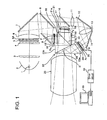
- Fig. 1 shows a schematic structure of a liquid crystal projector (a projection-type image display apparatus) using a projection-type display optical system of Embodiment 1 of the present invention.
- reference numeral 1 denotes a light source such as a super high-pressure mercury lamp.
- Reference numeral 2 denotes a reflector having a paraboloidal-shaped reflective surface (this may be an ellipsoidal shape), and a paraboloidal-shaped mirror is illustrated in the drawing.
- a light flux emitted from the light source 1 is converted to an approximately parallel light by being reflected by the reflector 2 and is made incident into a first fly-eye lens 3.
- the first fly-eye lens 3 is structured by arranging a plurality of rectangular lenses (convex lenses) having a positive optical power on a flat plate.
- Reference numeral 4 denotes a second fly-eye lens into which a light flux emerged from the first fly-eye lens 3 is made incident, and this is structured by arranging a plurality of rectangular lenses (plano-convex lenses) having a positive optical power on a flat plate. A light source image is formed almost at the center part of the respective lenses of the second fly-eye lens 4.
- Reference Numeral 5 denotes a polarization converting element array, which makes a non-polarized (randomly polarized) light made incident into each polarization converting element emerge as a linear polarized light having a specific polarizing direction.
- the polarizing directions of polarized lights emerging from the respective polarization converting elements are mutually coincident.
- a light made incident into the polarization converting element array 5 is, as a result of transmission of a P-wave (P-polarized light) and reflection of an S-wave (S-polarized light) at a polarization splitting layer (unillustrated), split into a P-wave and an S-wave.
- the P-wave is phase-converted by a ⁇ /2 phase plate 5A to be aligned with the S-wave in terms of the polarization axis direction. Accordingly, light fluxes emerging from the polarization converting element array 5 all become polarized lights having polarization axes in an identical direction.
- a polarization splitting layer (unillustrated) of the polarization converting element array 5 may have a characteristic of reflecting a P-wave and transmitting an S-wave.
- a light flux emerged from the polarization converting element array 5 is condensed by a first positive lens 6, is color-separated into three color light components of R (red), G (green), and B (blue) by a color separating optical system (which will be described later). Then, the three color light components are irradiated onto the display portions of transmissive liquid crystal display panels (image forming elements) Pr, Pg, and Pb provided for the respective RGB colors.
- Each of the transmissive liquid crystal display panels Pr, Pg, and Pb is a well-known transmissive liquid crystal display panel and has an effect to, when transmitting light, turn the polarizing direction of a polarized light made incident into specific pixels out of pixels contained by the liquid crystal display panel by 90° in accordance with signals outputted from an drive circuit 50 (described later) on the basis of image information from an image information supplying apparatus 60 (described later), that is, a function to convert a part of the incident light made incident as an S-polarized light to a P-polarized light.
- Such display panels are composed of TN-type liquid crystal display elements, for example.
- the blue light component reflected by a blue reflective dichroic mirror 8 is condensed in an S-polarized state at the display portion of the blue-light transmissive liquid crystal display panel Pb via a high-reflection mirror 9, a second positive lens 15, and a blue-light entrance-side polarizing plate 16. Then, a blue light (S-polarized light) made incident into, out of multiple pixels contained by the blue-light transmissive liquid crystal display panel Pb, a part of pixels corresponding to light (image light) projected onto a projection surface (unillustrated) such as a screen is converted from the S-polarized light to a P-polarized light.
- S-polarized light blue light
- the green light component out of green and red light components transmitted through the blue reflective dichroic mirror 8 is reflected by a green reflective dichroic mirror 10 and is condensed in an S-polarized state at the display portion of the green-light transmissive liquid crystal display panel Pg via a third positive lens 17 and a green-light entrance-side polarizing plate 18. Then, the green-light (S-polarized light) made incident into, out of multiple pixels contained by the green-light transmissive liquid crystal display panel Pg, a part of pixels corresponding to light (image light) projected onto the projection surface is converted from the S-polarized light to a P-polarized light.
- the red light component transmitted through the green reflective dichroic mirror 10 is condensed at the display portion of the red-light transmissive liquid crystal display panel Pr via a fourth positive lens 11, a high-reflection mirror 12, a fifth positive lens 13, a high reflection mirror 14, a sixth positive lens 19, and a red-light entrance-side polarizing plate 26.
- the light made incident into the liquid crystal display panel for each color is not necessarily an S-polarized light, and a P-polarized light may be made incident by the P-polarized light emerging from the polarization converting element.
- a drive circuit 50 is connected, and to the drive circuit 50, image information from an image information supplying apparatus 60 such as a personal computer, a video, a television, a DVD player, a digital camera (still or video camera) is supplied.
- the drive circuit 50 outputs a signal to make each transmissive liquid crystal display panel display an original image based on the supplied image information. Light made incident into each transmissive liquid crystal display panel is modulated according to the displayed original image.
- the projector according to the present embodiment forms an image display system by a combination with the image information supplying apparatus such as a personal computer.
- the image information supplying apparatus such as a personal computer.
- the blue light component modulated by the blue-light transmissive liquid crystal display panel Pb is, after being converted in its polarizing direction by 90° becoming an S-polarized light by a half-wave plate 30, made incident into a prism 21a of a polarization beam splitter (a first optical element) 21.
- This polarization beam splitter 21 is constructed by joining two prisms 21a and 21b having a mutually identical triangle pole shape and forming, at the joint surface, a polarization splitting film (a first optical film) P for reflecting an S-polarized light and transmitting a P-polarized light.
- the S-polarized light component which is an image light is selectively reflected by the polarization splitting film P, whereby an analysis is carried out.
- the green light component modulated by the green-light transmissive liquid crystal display panel Pg is made incident into the prism 21b of the polarization beam splitter 21. And, only a P-polarized light component is transmitted through the polarization splitting film P, whereby an analysis is carried out.
- the blue S-polarized light component reflected by the polarization splitting film P and the green P-polarized light component transmitted through the polarization splitting film P are combined and emerge from the polarization beam splitter 21.
- the red light component modulated by the red-light transmissive liquid crystal display panel Pr is, after being analyzed by a red-light exit-side polarizing plate 20, made incident into a prism 23a of a dichroic prism (a second optical element) 23.
- This dichroic prism 23 is constructed by joining two prisms 23a and 23b having triangle pole shapes mutually different in size and forming, at the joint surface, a dichroic film (a second optical film) D for reflecting a red light component and transmitting blue and green light components.
- the red light component made incident into the prism 23a is reflected twice including a reflection on the dichroic film D and emerges from the dichroic prism 23 in a manner combined with the blue and green light components transmitted through the dichroic film D.
- the red light component is reflected twice within the dichroic prism 23, however, the number of reflection times is not limited hereto and may be once, three times or more.
- a color combining prism (a color combining optical system) 22 is composed of the polarization beam splitter 21 and dichroic prism 23.
- the three-color image lights combined by the color combining prism 22 and emerged as such are projected by a projection lens 25 onto a screen (unillustrated), whereby a full color image is displayed.
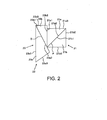
- the color combining prism 22 is, as described above, composed of the prisms 21a and 21b of the polarization beam splitter 21 and the prisms 23a and 23b of the dichroic prism 23.
- the color combining prism 22 formed of four prisms as such is also referred to as a four-piece prism.
- the prism 21a has a transmissive surface (a first (or second) incident surface) 21a3 which is an incident surface for the blue light component, a polarization splitting surface 21a2 on which a polarization splitting film P for reflecting an S-polarized light and transmitting a P-polarized light has been formed by vapor deposition, and a transmissive surface (first emergent surface) 21a1 which is an emergent surface for the blue and green light components.
- An S-polarized component out of the blue light component made incident through the transmissive surface 21a3 of the prism 21a is analyzed by being reflected by the polarization splitting film P, and emerges from the transmissive surface 21a1.
- the prism 21b has a transmissive surface (a second (or first) incident surface) 21a2 which is an incident surface for the green light component, a transmissive surface 21b1 to be joined to the polarization splitting surface 21a2 of the prism 21a, and a transmissive surface (a second emergent surface) 21b3 as a non-optical effective surface.
- a P-polarized component out of the green light component made incident into the prism 21b through the transmissive surface 21b2 and emerged from the transmissive surface 21b1 is analyzed by being transmitted through the polarization splitting film P, and emerges from the prism 21a by further being transmitted through the prism 21a.
- the blue S-polarized light component reflected by the polarization splitting film P and the green P-polarized light component transmitted through the polarization splitting film P are combined.
- the prisms 21a, 21b, 23a and 23b transmit light while maintaining a polarized state
- low-photoelasticity glass is preferably employed as a material of the prisms 21a, 21b, 23a, and 23b.
- the prism 23a has a surface (a third emergent surface) 23a1 which is a transmissive surface as an emergent surface and is also an internal reflecting surface to satisfy total reflection conditions for a red light component to be made incident, a dichroic surface 23a2 on which a dichroic film D for reflecting a red light component and transmitting blue and green light components has been formed by vapor deposition, and a transmissive surface (a fourth emergent surface) 23a3 which is an incident surface for the red light component.
- a third emergent surface 23a1 which is a transmissive surface as an emergent surface and is also an internal reflecting surface to satisfy total reflection conditions for a red light component to be made incident
- a transmissive surface (a fourth emergent surface) 23a3 which is an incident surface for the red light component.
- the prism 23b has a transmissive surface 23b1 to be joined to the dichroic surface 23a2 of the prism 23a, a transmissive surface (a third incident surface) 23b2 which is an incident surface for the blue and green light components emerged from the prism 21a, and a non-optical effective surface 23b3 as a transmissive surface.
- the red light component made incident through the transmissive surface 23a3 of the prism 23a is first totally reflected by the surface 23a1 and is then reflected by the dichroic film D. And, at this time, the red light component is combined with blue and green light components transmitted through the prism 23b and dichroic film D and is then transmitted through the surface 23a1 to emerge from the prism 23a (namely, the color combining prism 22).
- an antireflection coating film so as to prevent a light amount loss due to a surface reflected light produced at a boundary between the air and glass.
- an antireflection coating film so as to prevent unnecessary light produced by analysis at the polarization splitting film P from returning to the optical path for the projection by a surface reflection on the transmissive surface 21b3 and deteriorating a projected image in contrast.
- a light absorbing member 40 as a light processing member is arranged in a manner opposed to the transmissive surface 21b3 so as to absorb the unnecessary blue light emerged from the transmissive surface 21b3.
- the light absorbing member 40 provides similar effects for a green light component, as well.
- the aforementioned light absorbing member 40 which is arranged in a manner opposed to the transmissive surface (non-optical effective surface) 21b3, is used so as to absorb the green unnecessary light emerged from the transmissive surface 21b3.
- the light absorbing member 40 an aluminum plate to which black painting has been applied after a black alumite treatment can be used. Furthermore, by arranging this aluminum plate with a tilt with respect to the optical path, even if a slight amount of light to be reflected without being absorbed by the light absorbing member 40 is included in the unnecessary light, this can be prevented from returning to the optical path in the prism 21.
- the non-optical effective surface 23b3 of the prism 23b is, in order to prevent ghost caused by internal reflection in the prism 23b, not a polished surface but a sand ground surface, and furthermore, black paint is preferably applied.
- the dichroic film D formed on the dichroic surface 23a2 of the prism 23a may be formed on the transmissive surface 23b1 of the prism 23b. Since the prism 23b is smaller than the prism 23a, more prisms can be placed in a vapor deposition chamber when carrying out a vapor deposition of a dichroic film D, therefore, manufacturing costs can be reduced.
- the polarization splitting film P formed on the polarization splitting surface 21a2 of the prism 21a may be formed on the transmissive surface 21b1 of the prism 21b.
- a green light which is high in energy since the wavelength is short and is contained by a large amount in a blue light and white light, can be analyzed by a polarization beam splitter 21, therefore, it becomes unnecessary to provide an exit-side polarizing plate, whose performance is deteriorated by heat if a strong illuminating light is made incident, in the optical paths of the blue and green light components.
- an exit-side polarizing plate having high analysis performance namely, greater in the amount of light to be blocked
- a projected image through the liquid crystal projector can be brightened.
- a general polarization beam splitter has, particularly in terms of an angled light, a higher reflectivity in an S-polarized light than transmittance in a P-polarized light. Accordingly, analysis with an S-polarized light (namely, an S-polarized light of unnecessary light is reflected by the polarization beam splitter and is deflected from its optical path for projection onto a projection surface) is higher in performance as an analyzer than analysis with a P-polarized light (namely, a P-polarized light of unnecessary light is transmitted through the polarization beam splitter and is deflected from its optical path for projection onto the projection surface).
- a green light component which strongly influences contrast
- a polarizing plate may be arranged only either between the green-light liquid crystal display panel Pg and polarization beam splitter (first optical element) 21 or between the blue-light liquid crystal display panel Pb and polarization beam splitter 21.
- a member for blocking light other than a light component in a specific polarizing direction or a member such as a polarization beam splitter for splitting a specific polarized light component away from other polarized light components may be arranged. If a polarizing plate is arranged, analysis can be carried out twofold by the polarizing plate and polarization beam splitter, therefore, a color light component which passes through the optical path with the polarizing plate arranged can be improved in polarization purity.
- Embodiment 1 in terms of a green light having a high relative visibility, since analysis performance by the polarization beam splitter is sufficiently high, no polarizing plate is arranged. Moreover, in terms of a blue light component, for the reason that energy is high since the blue light wavelength is short and performance is deteriorated at a high temperature, no polarizing plate is arranged. As a matter of course, if the above problems are solved, a polarizing plate may be arranged on the optical path of the blue light.
- the exit-side polarizing plate 20 is provided and a color combination is carried out by a dichroic film D after a total reflection in the prism 23a (namely, reflected twice), therefore, the back focal distance of the projection lens 25 can be shortened, whereby the liquid crystal projector (projection-type image display apparatus) can be reduced in size.
- Fig. 3 shows a schematic structure of a liquid crystal projector (a projection-type image display apparatus) using a projection-type display optical system of Embodiment 2 of the present invention.
- the present embodiment is identical in its basic structure to Embodiment 1, therefore, symbols identical to those of Embodiment 1 are used for common components, and a description thereof is substituted by the identical symbols.
- a green light component reflected by a green reflective dichroic mirror 80 is condensed in an S-polarized state at the display portion of a green-light transmissive liquid crystal display panel Pg via a high-reflection mirror 9, a second positive lens 15, and a green-light entrance-side polarizing plate 160.
- a blue light component out of blue and red light components transmitted through the green reflective dichroic mirror 80 is reflected by a blue reflective dichroic mirror 100 and is condensed in an S-polarized state at the display portion of a blue light transmissive liquid crystal display panel Pb via a third positive lens 17 and a blue-light entrance-side polarizing plate 180.
- a red light component transmitted through the blue reflective dichroic mirror 100 is condensed at the display portion of a red-light trasmissive liquid crystal display panel Pr via a fourth positive lens 11, a high reflection mirror 12, a fifth positive lens 13, a high reflection-mirror 14, a sixth positive lens 19, and a red-light entrance-side polarizing plate 26.
- the fourth positive lens 11 and fifth positive lens 13 since only red channels are longer in the optical paths than other color channels, these play a role of relay lens system for approximately full-size image formation.
- the blue light component modulated by the green-light transmissive liquid crystal display panel Pg is, after being converted in its polarizing direction by 90° by a half-wave plate 32, transmitted through a green-light exit-side polarizing plate 31, and is made incident into a prism 21a constituting part of a polarization beam splitter 21 in a color combining prism 22.
- the green-light exit-side polarizing plate 31 is low in analysis performance and high in transmittance compared to other polarizing plates. Therefore, heat generation at the polarizing plate 31 as a result of analysis of the green light component is less of a problem.
- the blue light component modulated by the blue-light transmissive liquid crystal display panel Pb is made incident into a prism 21b of the polarization beam splitter 21.
- the blue-light liquid crystal display panel Pb and polarization beam splitter 21 are adjacent on the blue light optical path, and no optical element such as a polarizing plate is arranged therebetween. That is, the blue light component from the blue-light liquid crystal display panel Pb is made incident into the polarization beam splitter 21 as it is.
- the red light modulated by the red-light transmissive liquid crystal display panel Pr is made incident via a red-light exit-side polarizing plate 20 into a prism 23a constituting part of a dichroic prism 23 in the color combining prism 22.
- the three color components color-combined by the color combining prism 22 are projected by a projection lens 25 onto a screen (unillustrated).
- a general polarization beam splitter has, particularly in terms of an angled light, a higher reflectivity in an S-polarized light than transmittance in a P-polarized light, and analysis with an S-polarized light is higher in performance as an analyzer.
- the green light component which is high in comparative visibility and thus strongly influences brightness, is made incident, as an S-polarized light, into the polarization beam splitter 21 and is reflected by the polarization splitting surface P for projection, therefore, a liquid crystal projector which can project a bright image can be realized.
- the exit-side polarizing plate 31 is not always necessary.
- a light absorbing member 40 is arranged in a manner opposed to the non-optical effective surface 21b3.
- Fig. 4 shows a schematic structure of a liquid crystal projector (a projection-type image display apparatus) using a projection-type display optical system of Embodiment 3 of the present invention.
- the present embodiment is identical in the basic structure to Embodiment 1, therefore, symbols identical to those of Embodiment 1 are used for common components, and a description thereof is substituted by the identical symbols.
- a color selective phase plate 34 and a polarizing plate 35 are provided between the prism 21a of the polarization beam splitter 21 and prism 23b of the dichroic prism 23.
- the color selective phase plate 34 has an effect to change the polarized state of only a blue light component by 90°, and a color selective phase plate sold with a product name, ColorSelect® (registered trademark) by ColorLink, Inc. can be employed.
- the polarizing plate 35 transmits a P-polarized light and absorbs an S-polarized light.
- a P-polarized light mixed in a blue light component after a P-analysis which is inferior in analysis performance to an S-analysis, is converted to an S-polarized light by the color selective phase plate 34 and is absorbed in the polarizing plate 35, whereby a high contrast can be obtained in a projected image.
- a light absorbing member 40 is arranged in a manner opposed to the non-optical effective surface 21b3.
- the back focal distance of the projection optical system can be shortened.
- a bright projected image can be obtained and no large-scale cooling is necessary, and a small-sized color combining optical system, projection-type display optical system, and projection-type image display apparatus can be realized.
- a light processing member such as a light absorbing member, which prevents unnecessary light emerged from the first optical element (prism) from returning to the inside of an optical path, unnecessary light can be prevented from being irradiated into other optical paths or unnecessary light can be prevented from causing heat generation inside other optical paths.
- the first optical element by disposing a half-wave plate in the optical path of a color light to be analyzed with a P-polarized light in the first optical element (for example, in front of the incident surface of the first optical element) and then analyzing a color light by the first optical element after a conversion to an S-polarized light, polarizing conditions of all color lights made incident into the first optical element are made uniform, therefore, the first optical element can be easily designed.
- the polarizing plate may be of a low analysis performance of such a degree as to cause no thermal problem.
- a polarizing plate between the first optical element and second optical element to block unnecessary light leaking out from the first optical element so as to obtain a further higher contrast.
Landscapes
- Physics & Mathematics (AREA)
- General Physics & Mathematics (AREA)
- Optics & Photonics (AREA)
- Projection Apparatus (AREA)
- Liquid Crystal (AREA)
- Polarising Elements (AREA)
- Video Image Reproduction Devices For Color Tv Systems (AREA)
- Optical Elements Other Than Lenses (AREA)
Applications Claiming Priority (2)
| Application Number | Priority Date | Filing Date | Title |
|---|---|---|---|
| JP2002224016 | 2002-07-31 | ||
| JP2002224016A JP2004062092A (ja) | 2002-07-31 | 2002-07-31 | 色合成光学系、投射型表示光学系、投射型画像表示装置および画像表示システム |
Publications (2)
| Publication Number | Publication Date |
|---|---|
| EP1387206A2 true EP1387206A2 (fr) | 2004-02-04 |
| EP1387206A3 EP1387206A3 (fr) | 2005-02-09 |
Family
ID=30112970
Family Applications (1)
| Application Number | Title | Priority Date | Filing Date |
|---|---|---|---|
| EP03254735A Withdrawn EP1387206A3 (fr) | 2002-07-31 | 2003-07-29 | Système optique à combinaison de couleurs, système d'affichage optique de type projection, affichage optique de type projection et système d'affichage optique |
Country Status (4)
| Country | Link |
|---|---|
| US (1) | US6992833B2 (fr) |
| EP (1) | EP1387206A3 (fr) |
| JP (1) | JP2004062092A (fr) |
| CN (1) | CN1232863C (fr) |
Cited By (1)
| Publication number | Priority date | Publication date | Assignee | Title |
|---|---|---|---|---|
| WO2005088383A1 (fr) * | 2004-03-10 | 2005-09-22 | Raytheon Company | Viseur optique comprenant une unite destinee a combiner des informations en provenance d'un afficheur a cristaux liquides |
Families Citing this family (7)
| Publication number | Priority date | Publication date | Assignee | Title |
|---|---|---|---|---|
| JP2007163597A (ja) * | 2005-12-09 | 2007-06-28 | Canon Inc | 波長選択性偏光変換素子、照明光学系、投射表示光学系および画像投射装置 |
| DE102005061182B4 (de) * | 2005-12-21 | 2020-03-19 | Carl Zeiss Jena Gmbh | Beleuchtungseinrichtung zur Farbbildprojektion |
| CN101311773B (zh) * | 2007-05-24 | 2011-06-15 | 程思洋 | 多基色图像叠加器 |
| DE102015101847B4 (de) * | 2015-02-10 | 2017-11-02 | Eyesense Gmbh | Strahlteiler und Anordnung zur Untersuchung einer mittels elektromagnetischer Strahlung anregbaren Probe |
| JP7417892B2 (ja) * | 2019-12-26 | 2024-01-19 | パナソニックIpマネジメント株式会社 | 表示装置および投写装置 |
| CN111474173B (zh) * | 2020-04-26 | 2022-12-16 | 山东省地质矿产勘查开发局第一地质大队 | 岩石中透明矿物突起等级的确定方法、系统及应用 |
| JP7672277B2 (ja) * | 2021-05-14 | 2025-05-07 | パナソニックホールディングス株式会社 | 投写型映像表示装置 |
Family Cites Families (20)
| Publication number | Priority date | Publication date | Assignee | Title |
|---|---|---|---|---|
| JP3039570B2 (ja) * | 1991-06-24 | 2000-05-08 | キヤノン株式会社 | 投写表示装置 |
| JP3396270B2 (ja) * | 1993-08-10 | 2003-04-14 | 富士通株式会社 | 光分散補償方式 |
| JPH07306405A (ja) | 1994-05-13 | 1995-11-21 | Victor Co Of Japan Ltd | 液晶表示装置 |
| US5999240A (en) * | 1995-05-23 | 1999-12-07 | Colorlink, Inc. | Optical retarder stack pair for transforming input light into polarization states having saturated color spectra |
| US5751384A (en) * | 1995-05-23 | 1998-05-12 | The Board Of Regents Of The University Of Colorado | Color polarizers for polarizing an additive color spectrum along a first axis and it's compliment along a second axis |
| US6252638B1 (en) * | 1995-05-23 | 2001-06-26 | Colorlink, Inc. | Color controllable illumination device, indicator lights, transmissive windows and color filters employing retarder stacks |
| US6183091B1 (en) * | 1995-04-07 | 2001-02-06 | Colorlink, Inc. | Color imaging systems and methods |
| US6380997B1 (en) * | 1995-04-07 | 2002-04-30 | Colorlink, Inc. | Achromatic polarization inverters for displaying inverse frames in DC balanced liquid crystal displays |
| US6704065B1 (en) * | 1995-04-07 | 2004-03-09 | Colorlink, Inc. | Optical system for producing a modulated color image |
| US6273571B1 (en) * | 1995-05-23 | 2001-08-14 | Colorlink, Inc. | Display architectures using an electronically controlled optical retarder stack |
| US6417892B1 (en) * | 1995-05-23 | 2002-07-09 | Colorlink, Inc. | Color filters, sequencers and displays using color selective light modulators |
| US6507326B2 (en) * | 1996-07-10 | 2003-01-14 | Nikon Corporation | Color-projection apparatus operable to project a high-contrast image with minimal change in the state or phase of polarization of light flux |
| US6176586B1 (en) * | 1998-03-24 | 2001-01-23 | Minolta Co., Ltd. | Projection display apparatus |
| JP2000227578A (ja) * | 1998-11-12 | 2000-08-15 | Fujitsu Ltd | 投写型表示装置 |
| JP2001066695A (ja) * | 1999-08-31 | 2001-03-16 | Fuji Photo Optical Co Ltd | プロジェクタ装置 |
| WO2001073485A1 (fr) * | 2000-03-27 | 2001-10-04 | Digital Reflections, Inc. | Ensemble prisme a rendement eleve pour projection d'images |
| JP3610280B2 (ja) * | 2000-04-07 | 2005-01-12 | キヤノン株式会社 | 色合成光学素子およびそれを用いた投写型画像表示装置 |
| JP4049990B2 (ja) | 2000-11-30 | 2008-02-20 | 株式会社リコー | プロジェクタ及び偏光変換器 |
| JP2002182307A (ja) * | 2000-12-13 | 2002-06-26 | Minolta Co Ltd | 投射型表示装置 |
| JP3508753B2 (ja) | 2001-10-15 | 2004-03-22 | ソニー株式会社 | 画像表示装置 |
-
2002
- 2002-07-31 JP JP2002224016A patent/JP2004062092A/ja active Pending
-
2003
- 2003-07-29 EP EP03254735A patent/EP1387206A3/fr not_active Withdrawn
- 2003-07-31 US US10/631,393 patent/US6992833B2/en not_active Expired - Fee Related
- 2003-07-31 CN CN03152377.3A patent/CN1232863C/zh not_active Expired - Fee Related
Cited By (2)
| Publication number | Priority date | Publication date | Assignee | Title |
|---|---|---|---|---|
| WO2005088383A1 (fr) * | 2004-03-10 | 2005-09-22 | Raytheon Company | Viseur optique comprenant une unite destinee a combiner des informations en provenance d'un afficheur a cristaux liquides |
| US7948682B2 (en) | 2004-03-10 | 2011-05-24 | Raytheon Company | Method and apparatus for combining optical information |
Also Published As
| Publication number | Publication date |
|---|---|
| JP2004062092A (ja) | 2004-02-26 |
| EP1387206A3 (fr) | 2005-02-09 |
| US20050174652A1 (en) | 2005-08-11 |
| CN1480766A (zh) | 2004-03-10 |
| CN1232863C (zh) | 2005-12-21 |
| US6992833B2 (en) | 2006-01-31 |
Similar Documents
| Publication | Publication Date | Title |
|---|---|---|
| CN100361021C (zh) | 照明光学系统、图像显示装置以及照明空间调节器的方法 | |
| US7195373B2 (en) | Illuminating device and projection type video display | |
| US6678015B2 (en) | Color separating/synthesizing apparatus | |
| US6067128A (en) | Liquid-crystal display projector including an optical path adjuster arranged in the light path from the light source to the liquid-crystal display element | |
| JP3417757B2 (ja) | 液晶表示装置およびその光束分離方法 | |
| JP4040484B2 (ja) | 偏光分離光学系、投射型表示光学系、投射型画像表示装置および画像表示システム | |
| US12072618B2 (en) | Light source device and projection display apparatus | |
| US20090237616A1 (en) | Projection type image display device | |
| US7137704B2 (en) | Color splitting/combining optical system and image projecting apparatus | |
| JP3951897B2 (ja) | 偏光変換ユニット及びこれを用いたプロジェクタ | |
| US6992833B2 (en) | Color combining optical system, projection-type display optical system, projection-type image display apparatus, and image display system | |
| US20020089679A1 (en) | Color separating/synthesizing apparatus | |
| US8308300B2 (en) | Color separation optical system and image projection apparatus | |
| US7597446B2 (en) | Illumination optical system and image projection apparatus | |
| US7472995B2 (en) | Wavelength-selective polarization conversion element, projection displaying optical system and image projection apparatus | |
| JP3654798B2 (ja) | 画像表示装置および照明装置 | |
| JP4610577B2 (ja) | 投射型表示装置 | |
| JP4172532B2 (ja) | 投射型液晶表示装置 | |
| JP2002090874A (ja) | 光学装置およびそれを用いた投射型表示装置 | |
| JP2003337375A (ja) | プロジェクタ | |
| JP2818537B2 (ja) | 偏光光源装置を用いた液晶プロジェクタ | |
| JP2002122810A (ja) | 光学エンジン及びそれを用いた映像表示装置 | |
| JP4731744B2 (ja) | 偏光型光路分離素子および色分離合成素子および色分離方法および色合成方法およびカラー映像光合成装置およびカラー映像光合成方法および投影装置 | |
| JP2800812B2 (ja) | カラー画像生成ユニット | |
| JPH06186521A (ja) | 液晶プロジェクター |
Legal Events
| Date | Code | Title | Description |
|---|---|---|---|
| PUAI | Public reference made under article 153(3) epc to a published international application that has entered the european phase |
Free format text: ORIGINAL CODE: 0009012 |
|
| AK | Designated contracting states |
Kind code of ref document: A2 Designated state(s): AT BE BG CH CY CZ DE DK EE ES FI FR GB GR HU IE IT LI LU MC NL PT RO SE SI SK TR |
|
| AX | Request for extension of the european patent |
Extension state: AL LT LV MK |
|
| PUAL | Search report despatched |
Free format text: ORIGINAL CODE: 0009013 |
|
| AK | Designated contracting states |
Kind code of ref document: A3 Designated state(s): AT BE BG CH CY CZ DE DK EE ES FI FR GB GR HU IE IT LI LU MC NL PT RO SE SI SK TR |
|
| AX | Request for extension of the european patent |
Extension state: AL LT LV MK |
|
| RIC1 | Information provided on ipc code assigned before grant |
Ipc: 7G 02B 27/28 B Ipc: 7G 02B 27/14 A |
|
| 17P | Request for examination filed |
Effective date: 20050701 |
|
| AKX | Designation fees paid |
Designated state(s): DE FR GB IT NL SE |
|
| STAA | Information on the status of an ep patent application or granted ep patent |
Free format text: STATUS: THE APPLICATION HAS BEEN WITHDRAWN |
|
| 18W | Application withdrawn |
Effective date: 20081024 |